1
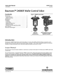
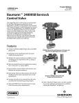
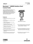
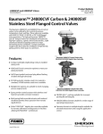
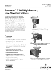
Product Bulletin 24000F Valve 52.1:24WF March 2013 D103330X012 Baumann™ 24000F Wafer Body Control Valve The Baumann unique 24000F wafer style control valve mates with ASME and EN line flange connections and is designed to control a wide range of process liquids, gases and vapors. This very compact package provides the connection integrity of flanged body globe valves while being significantly lighter and easier to install. Special alloy constructions are available and round out the standard S31603 stainless steel offering. The 24000F serves as a general purpose, modulating valve suitable for process line pressures up to 99 barg (1440 psig) and operating temperatures to 537_C (1000_F). Features Compact and light-weight design reduces installed piping costs. Universal valve body construction mates with both ASME and EN flanges (see table 9). Multiple trim capacity reductions available to meet changing process requirements with Cv ratings as low as 0.00013. Optional extended bonnet for applications ranging from -195 to 537_C (-320 to 1000_F). Optional ENVIRO-SEAL™ packing system to meet critical emission control requirements Epoxy powder-coated actuator with stainless steel fasteners for corrosion resistance. W9762 24000F Control Valve with Baumann 32 Dual-Stop Actuator W9763 Multi-spring, field-reversible actuator with reduced deadband, permits direct operation from remote signal devices. Actuator and yoke can be removed from the valve assembly while maintaining packing integrity. 24000F Control Valve with Baumann 32 Actuator and FIELDVUE DVC2000 Digital Valve Controller www.Fisher.com Fisherr FIELDVUE™ digital valve controller available for remote calibration and diagnostics in facilities utilizing the PlantWeb™ architecture. Product Bulletin 24000F Valve 52.1:24WF March 2013 Figure 1. Baumann 24000F Valve Body with Standard Bonnet and NPS 1 Integral Seat D103330X012 Figure 2. Baumann 24000F Valve Body with Extension Bonnet and Screwed-In Seat Ring E1278 E1279 2 Product Bulletin 24000F Valve 52.1:24WF March 2013 D103330X012 Table 1. Materials of Construction Key No. Material Description S31603 Stainless Steel N10276 Nickel Alloy(1) N08020 Nickel Alloy(1) N04400 Nickel Alloy(1) ASME SB574 N10276 ASTM B473 N08020 ASME SB164 N04400 ASME SB574 N10276 ASTM B473 N08020 ASME SB164 N04400 ASME SB574 N10276 ASTM B473 N08020 ASME SB164 N04400 1 Valve Body ASME SA479 S31600/ S31603 Dual Certified 2 Seat Ring (standard) (For Low Flow Trim, see tables 2 and 3) ASTM A276 S31600/ S31603 Dual Certified Plug (Metal Seat) Cv ≤ 2.5 ASME SA479 S21800 (standard) / ASTM A582 S41600 Condition T (optional) Plug (Metal Seat) Cv ≥ 4.0 ASTM A276 S31600/ S31603(standard) / ASTM A582 S41600 Condition T (optional) Plug (Soft Seat) ASTM A276 S31600/ S31603 with PTFE (Polytetrafluoroethylene) insert ASME SB574 N10276/PTFE ASTM B473 N08020/PTFE ASME SB164 N04400/ PTFE Stem ASTM A276 S31600 ASME SB574 N10276 ASTM B473 N08020 ASME SB164 N04400 8 Bonnet ASME SA479 S31600/ S31603 Dual Certified ASME SB574 N10276 ASTM B473 N08020 ASME SB164 N04400 9 Drive Nut (Yoke) ASTM B473 N08020 ASME SB164 N04400 4 5 10 S30400 ASTM A276 S31600/ S31603 Dual Certified Packing Follower V- Ring Packing (standard) 14 ASME SB574 N10276 (Refer to page 4) Packing (optional) (Refer to page 4) Lock Nut Stainless Steel (18-8 Stainless Steel) 49 Body Gasket Graphite Grade GHR with S31600 Insert 58 Travel Indicator ASME SA240 S30400 27 1. For optional valve and trim materials, consult your Emerson Process Management sales office for price and delivery. N08020 and N04400 nickel alloy materials have pressure-temperature ratings less than 206 barg (3000 psig) or 413 barg (6000 psig) respectively. Figure 3. Optional 151 Low Flow Trim Assembly E1270 Figure 4. Optional 177 Low Flow Trim Assembly E1271 Table 2. 151 Low Flow Trim Key Number Description 4 Plug Table 3. 177 Low Flow Trim Material 52 Cage ASTM A276 S31600/ S31603 53 Seat PTFE 54 Collar ASTM A276 S31600/ S31603 55 Washer ASTM A276 S31600 Cond B 56 Insert ASTM A276 S31600/ S31603 Description Material Seat Sub-Assembly ASME SA479 S21800 Seat Sub-Assembly 51 Key Number 2(1) 4(1) 23 Gland ASTM A276 S31600/ S31603 24 Retainer Nut ASTM A276 S31600/ S31603 25 Insert Reinforced PTFE 26 Housing ASTM A276 S31600/ S31603 Plug ASME SA479 S21800 1. For optional trim materials, consult your Emerson Process Management sales office for price and delivery. Baumann 32 actuator requires dual-stops with 177 trim series. 3 Product Bulletin 24000F Valve 52.1:24WF March 2013 D103330X012 Figure 5. Standard Spring-Loaded PTFE V-Ring Packing Kit Figure 7. ENVIRO-SEAL Packing Kit (Optional) E1240 E1248 Table 4. Standard Spring-Loaded PTFE V-Ring Packing Kit Key Number Description Material 6(1) Spring ASTM A313 S30200 14 Packing Set PTFE (Polytetrafluoroethylene) / PTFE, 25% carbon filled 16 Washer ASME SA240 S31600 20 Spacer J-2000 (filled-Polytetrafluoroethylene) Table 6. ENVIRO-SEAL Packing Kit (Optional) Key Number Description Material 13 Bushings Carbon-Graphite 14 Packing Rings PTFE (Polytetrafluoroethylene) / PTFE, 25% carbon filled 17 Belleville Spring N06600 Nickel Alloy (ASTM B637 N07718, 40 HRC max) 18 Bushing PEEK (polyetheretherketone) 19 Washers Modified PTFE 1. N10276 nickel alloy valve body construction is furnished with N10276 nickel alloy spring. Figure 6. Molded Graphite (Flexible Graphite) Packing Kit (Optional) Special ENVIRO-SEAL Packing Note The ENVIRO-SEAL PTFE packing system is suitable for 100 ppm environmental applications on services up to 51.7 barg (750 psig) and process temperatures ranging from -46 to 232_C (-50 to 450_F). For non-environmental applications, this packing system offers excellent performance at the same temperature range up to the maximum valve working pressure. E1241 Table 5. Molded Graphite (Flexible Graphite) Packing Kit (Optional) Key Number Description Material 13 Bushings Carbon-Graphite 14A Packing Rings Graphite 14B Packing Ring Graphite 4 Temperature limits apply to packing arrangements only. Complete valve assembly temperature limits may differ, refer to appropriate pressure/temperature ratings. (Reference Fisher Packing Selection Guidelines for Sliding-Stem Valves, Bulletin 59.1:062, D101986X012). Product Bulletin 24000F Valve 52.1:24WF March 2013 D103330X012 Table 7. Technical Specifications DN 15, 20, and 25 NOMINAL PIPE SIZE NPS 1/2, 3/4, and 1 END CONNECTIONS Refer to table 9 PRESSURE RATING Refer to tables 13, 14, 15, and 16 CHARACTERISTIC Equal Percentage or Linear Table 8. Temperature Ratings for Packing and Seat Material(1) PTFE Soft Seat SEATING MATERIAL -29 to 177_C (-20 to 350_F) -73 to 232_C (-100 to 450_F) Reinforced PTFE 177 Trim -73 to 232_C (-100 to 450_F) Metal Seat 102, 548, 588, 648, 688 Trim -195 to 537_C (-320 to 1000_F) BONNET STYLE Standard Bonnet PACKING AND BONNET COMBINATIONS 151 Trim 577 & 677 Trim Extension Bonnet PACKING TEMPERATURE LIMIT Spring Loaded PTFE -73 to 232_C (-100 to 450_F) ENVIRO-SEAL -45 to 232_C (-50 to 450_F) Graphite -73 to 232_C (-100 to 450_F) Spring Loaded PTFE -195 to 232_C (-320 to 450_F) ENVIRO-SEAL -45 to 232_C (-50 to 450_F) Graphite -195 to 537_C (-320 to 1000_F) 1. Temperature limits apply to seating or packing arrangements only. Complete valve assembly temperature limits may differ, refer to appropriate pressure/temperature ratings. For more information on packing selection, reference Fisher Packing Selection Guidelines for Sliding- Stem Valves, Bulletin 59.1:062, D101986X012. Table 9. Connections Available VALVE SIZE CONNECTIONS MATING LINE FLANGES DN NPS CL150 CL300 CL600 PN10-40 15 1/2 NO Yes Yes Yes 20 3/4 Yes Yes Yes Yes 25 1 Yes Yes Yes Yes Table 10. Actuator Specifications TYPE 32, 54, 70 Multi-Spring Diaphragm (Single Acting) DIAPHRAGM AREA 210, 350, 450 cm2 / 32, 54, 70 in2 AIR FAILURE 32 and 54 Fails Open or Closed (Field Reversible) / 70 Fails Closed ONLY TRAVEL(1) 12.7 mm / 0.50 inches AMBIENT TEMPERATURE RANGE -29_C to 71_C / -20_F to 160_F MAXIMUM AIR PRESSURE 2.4 barg / 35 psig DIAPHRAGM MATERIAL(2) NBR (Nitrile) / TPES (Polyester Thermoplastic) SPRING CASES Steel, Powder Epoxy-Coated with Stainless Steel Fasteners YOKE Ductile Iron, Powder Epoxy-Coated 1. Dual travel stops are available on Baumann 32 and 54 actuators. These are not field reversible. 2. Optional reinforced VMQ (Silicone) diaphragm with FKM (Fluorocarbon) O-ring actuator stem seal for high temperature conditions (-29_C to 121_C / -20_F to 250_F) is available with Baumann 32 and 54 actuators ONLY. 5 Product Bulletin 24000F Valve 52.1:24WF March 2013 D103330X012 Table 11. Cv Values at 100% Plug Opening (Kv = 0.86 x Cv) VALVE SIZE DN 15 20 25 NPS ORIFICE DIAMETER mm inch PLUG TRAVEL mm inch PLUG SERIES 102 151 177 577 548 / 588 677 648 / 688 Cv Cv Cv Cv Cv Cv Cv --- --- --- --- --- 3.97 0.156 12.7 0.50 --- 0.00013 0.00025 0.0005 0.001 0.002 0.004 0.008 0.015 0.03 0.06 0.10 0.20 0.45 6.3 0.25 12.7 0.50 0.02 0.05 0.10 0.20 --- --- --- 0.2 0.5 1.0 --- 0.5 1.0 --- --- --- --- 1/2 3/4 1 7.9 0.3125 12.7 0.50 --- --- 0.0005 0.001, 0.002 0.005, 0.01 0.02, 0.05 15 20 1/2 3/4 9.5 0.375 12.7 0.50 --- --- --- 1.0, 1.5 2.0 1.5 2.0 0.1, 0.2, 0.5, 1.0, 2.0 1.5 2.0 25 1 9.5 0.375 12.7 0.50 --- --- --- 1.0, 1.5 2.5 2.5 0.1, 0.2, 0.5, 1.0, 2.5 1.5 2.5 25(1) 1 20.6 0.8125 12.7 0.50 --- --- --- 4.0, 6.5 4.0, 6.5 4.0 4.0, 6.5 1. 24000F NPS 1, Cv 4.0 and 6.5 are integral seat. Figure 8. Baumann 24000F Trims 102 Linear Low Flow Trim W9747 6 151 Modified Equal % Low Flow Trim W9751 W9748 648 / 677 / 688 Linear Trim 548 / 577 / 588 Equal % Trim 177 Modified Equal % Low Flow Trim W9749 W9750 Product Bulletin 24000F Valve 52.1:24WF March 2013 D103330X012 Table 12. ISA Sizing Coefficients Series 102 151 Cv Rating 0.02 0.04 0.09 0.17 0.0001 0.0002 0.0004 0.0009 0.0017 0.003 0.007 0.013 0.026 0.052 0.09 0.17 0.39 177 0.0005 0.001 0.002 0.005 0.01 0.02 0.05 548/588 0.2 0.5 1 1.5 2 2.5 4 6.5 577 1 1.5 2 4 6.5 677 0.1 0.2 0.5 1 2 2.5 4 648/688 0.5 1 1.5 2 2.5 4 6.5 FL 0.95 0.98 Fd 0.06 0.09 0.013 0.18 0.35 0.04 0.05 0.06 0.075 0.10 0.11 0.15 0.18 0.22 0.25 0.30 0.40 XT KC 0.76 0.86 0.81 0.94 0.76 0.95 0.70 0.76 0.90 0.28 0.68 0.90 0.40 0.33 0.42 0.94 0.68 0.46 0.90 0.40 0.33 0.42 0.68 0.73 0.68 0.73 0.68 0.73 0.46 0.90 0.08 0.12 0.19 0.27 0.46 0.40 0.33 0.42 0.90 0.46 7 Product Bulletin 24000F Valve 52.1:24WF March 2013 D103330X012 Table 13. Pressure-Temperature Ratings for S31603 Stainless Steel Valve Body (Standard) Temperature (_C)(1) Working Pressure (barg) Temperature (_F)(1) Working Pressure (psig) -195 to 37 99 -320 to 100 1440 93 85 200 1240 149 77 300 1120 204 70 400 1025 232 68 450 990 260 65 500 955 288 63 550 927 315 62 600 900 343 61 650 890 371 60 700 870 398 58 750 855 426 58 800 845 454 57 850 835 482 57 900 830 510 53 950 775 537 48 1000 700 1. Do not exceed seating and packing material ratings. Table 14. Pressure-Temperature Ratings for N10276 Nickel Alloy Valve Body (Optional) Temperature (_C)(1) Working Pressure (barg) Temperature (_F)(1) Working Pressure (psig) -195 to 37 103 -320 to 100 1500 93 103 200 1500 149 100 300 1455 204 97 400 1410 232 94 450 1370 260 91 500 1330 288 87 550 1270 315 83 600 1210 343 81 650 1175 371 78 700 1135 398 73 750 1065 426 69 800 1015 454 67 850 975 482 62 900 900 510 53 950 775 537 49 1000 725 1. Do not exceed seating and packing material ratings. 8 Product Bulletin 24000F Valve 52.1:24WF March 2013 D103330X012 Table 15. Pressure-Temperature Ratings for N04400 Nickel Alloy Valve Body (Optional) Temperature (_C)(1) Working Pressure (barg) Temperature (_F)(1) Working Pressure (psig) -195 to 37 82 -320 to 100 1200 93 72 200 1055 149 68 300 990 204 65 400 955 232 65 450 952 260 65 500 950 288 65 550 950 315 65 600 950 343 65 650 950 371 65 700 950 398 64 750 935 426 63 800 915 454 46 850 680 482 34 900 495 1. Do not exceed seating and packing material ratings. Table 16. Pressure-Temperature Ratings for N08020 Nickel Alloy Valve Body (Optional) Temperature (_C)(1) Working Pressure (barg) Temperature (_F)(1) Working Pressure (psig) -195 to 37 82 -320 to 100 1200 93 72 200 1045 149 67 300 980 204 67 400 980 232 67 450 980 260 67 500 980 288 67 550 980 315 67 600 980 343 67 650 980 371 67 700 980 398 67 750 980 426 67 800 980 1. Do not exceed seating and packing material ratings. 9 Product Bulletin 24000F Valve 52.1:24WF March 2013 D103330X012 Table 17. Allowable Pressure Drops (bar) AIR-TO-OPEN ACTION PORT DIA. (mm) PLUG TRAVEL (mm) 6.4 12.7 7.9 9.5 20.6 12.7 12.7 12.7 ACT TYPE BENCH RANGE (barg) 32 32 0.2-1.0 barg SIGNAL TO ACTUATOR AIR-TO-CLOSE ACTION WITH POSITIONER 1.38 barg AIR SUPPLY Max CL Max CL IV VI Shutoff Shutoff Pressure Pressure Max CL IV Shutoff Pressure Max CL VI Shutoff Pressure 0.3-1.0 61 --- 99 --- 0.5-1.0 99 --- 99(1) --- 32 0.3-1.0 --- 28 --- 32 0.5-1.0 --- 71 32 0.3-1.0 31 19 32 0.5-1.0 62 50 54 0.6-1.0 99(1) 32 0.3-1.0 7.7 32 0.5-1.0 54 0.5-1.0 54 70 BENCH RANGE (barg) 0.2-1.0 barg SIGNAL TO ACTUATOR WITH POSITIONER 1.38 barg AIR SUPPLY Max CL Max CL IV VI Shutoff Shutoff Pressure Pressure Max CL IV Shutoff Pressure Max CL VI Shutoff Pressure 0.2-0.9 61 --- 99(1) 0.2-0.7 99(1) --- 99(1,2) --- 71 0.2-0.9 --- 28 --- 99(1) --- 99 0.2-0.7 --- 92 --- 99(1,2) 62 50 0.2-0.9 31 19.1 99 97 93 81 0.2-0.7 77 65 99(1) 99(1) 99(1) 99(1,2) 99(1,2) 0.2-0.7 --- --- --- --- 1.3 15.5 9.1 0.2-0.9 7.7 1.3 27 20 15.5 9.1 23 16.8 0.2-0.7 19.5 12.9 38 32 23 17.0 35 28 0.2-0.7 29.5 23 59 52 0.8-1.0 47 40 59 52 --- --- --- --- --- 0.7-1.0 56 49 72 65 --- --- --- --- --- --- 1. The maximum shutoff pressure when using ENVIRO-SEAL packing is defined by: nP = Table Value - [1112/(Port Diameter)2]. These table values should not be modified by this formula and the maximum nP of 51 bar should be used for ENVIRO-SEAL packing. 2. The maximum shutoff pressure when using Flexible Graphite packing is defined by: nP = Table Value - [5337/(Port Diameter)2]. These table values should not be modified by this formula and the maximum nP of 99 bar should be used for Flexible Graphite packing. Table 18. Allowable Pressure Drops (psi) AIR-TO-OPEN ACTION PORT DIA. (in) PLUG TRAVEL (in) 0.25 0.50 0.3125 0.50 0.375 0.50 0.8125 0.50 3-15 psig SIGNAL TO ACTUATOR Max CL Max CL IV VI Shutoff Shutoff Pressure Pressure AIR-TO-CLOSE ACTION WITH POSITIONER 20 psig AIR SUPPLY Max CL Max CL IV VI Shutoff Shutoff Pressure Pressure 3-15 psig SIGNAL TO ACTUATOR Max CL Max CL IV VI Shutoff Shutoff Pressure Pressure WITH POSITIONER 20 psig AIR SUPPLY Max CL Max CL IV VI Shutoff Shutoff Pressure Pressure ACT TYPE BENCH RANGE (psig) 32 5-15 887 --- 1440 --- 3-13 887 --- 1440(1) 32 7-15 1440 --- 1440(1) --- 3-10 1440(1) --- 1440(1,2) --- 32 5-15 --- 418 --- 1033 3-13 --- 418 --- 1440(1) 32 7-15 --- 1033 --- 1440 3-10 --- 1341 --- 1440(1,2) 32 5-15 452 278 905 730 3-13 452 278 1440 1409 32 7-15 905 730 1357 1182 3-10 1131 956 1440(1) 1440(1) 54 9-15 1440(1) 1440(1) 1440(1,2) 1440(1,2) 3-10 --- --- --- --- 32 5-15 113 19 226 132 3-13 113 19 396 301 32 7-15 226 132 339 245 3-10 283 188 565 471 54 7-15 343 248 514 419 3-10 428 334 856 762 54 11-15 685 591 856 762 --- --- --- --- --- 70 10-15 815 720 1048 953 --- --- --- --- --- BENCH RANGE (psig) --- 1. The maximum shutoff pressure when using ENVIRO-SEAL packing is defined by: nP = Table Value - [25/(Port Diameter)2]. These table values should not be modified by this formula and the maximum nP of 750 psi should be used for ENVIRO-SEAL packing. 2. The maximum shutoff pressure when using Flexible Graphite packing is defined by: nP = Table Value - [120/(Port Diameter)2]. These table values should not be modified by this formula and the maximum nP of 1440 psi should be used for Flexible Graphite packing. 10 Product Bulletin 24000F Valve 52.1:24WF March 2013 D103330X012 Figure 9. Dimensional Drawings 333 (413.1) 279 (411.0) 216 (48.5) 216 (48.5) 141 (5.5) 60 (2.4) 127 (5.0) 229 (9.0) 3/4 INCH SQUARE 31 (1.24) 229 (9.0) 271 (10.7) 276 (10.9) BAUMANN 32 ACTUATOR WITH ADJUSTABLE OPEN/ CLOSE DUAL TRAVEL STOPS A C BAUMANN 54 ACTUATOR w/ FIELDVUE DVC2000 DIGITAL VALVE CONTROLLER BAUMANN 70 ACTUATOR w/ FIELDVUE DVC6010 DIGITAL VALVE CONTROLLER 4B BAUMANN 32 ACTUATOR with 3660/3661 POSITIONER 216 (48.5) 160 (46.3) 216 (48.5) 152 (46.0) 130 (5.1) MAX BAUMANN 54 ATC / FAIL OPEN ACTUATOR WITH HANDWHEEL BAUMANN 54 ATO/FAIL CLOSED ACTUATOR w/ HANDWHEEL BAUMANN 32 ATC/ FAIL OPEN ACTUATOR WITH HANDWHEEL BAUMANN 32 ATO/ FAIL CLOSED ACTUATOR WITH HANDWHEEL 160 (46.3) 279 (411.0) 152 (46.0) 71 (2.8) MAX 163 (6.4) MAX 94 (3.7) MAX 279 (411.0) mm (inch) E1280 Note: Actuator removal requires 115 mm (4.5 inches) vertical clearance. Table 19. Valve Dimensions A BONNET VALVE SIZE Standard B DIAMETER Extension C DN NPS mm Inch mm Inch mm Inch mm Inch 15 1/2 83.8 3.3 218.4 8.6 88.9 3.5 38.1 1.5 20 3/4 83.8 3.3 218.4 8.6 107.95 4.25 38.1 1.5 25 1 78.7 3.1 215.9 8.5 114.3 4.5 50.8 2.0 11 Product Bulletin 24000F Valve 52.1:24WF March 2013 D103330X012 Table 20. Valve Assembly Weights VALVE SIZE Table 21. Actuator Weights WEIGHT WEIGHTS ACTUATOR TYPE kg lb 32 4.5 10 5.3 54 11.3 25 7.3 70 15.4 34 MV 10 22 VA 14 30 DN NPS kg lb 15 1/2 1.7 3.8 20 3/4 2.4 25 1 3.3 Table 22. Model Numbering System Actuator 32(1) 54 24 F Valve Body Series Wafer Valve Body Plug Series Characteristic Seat Leakage 102 Linear / Metal Seat IV --- Standard 151 Modified Equal % / PTFE Seat VI E Extension 70 177 Modified Equal % / Reinforced PTFE VI mv 548 Equal % / Metal Seat (S41600) IV va 577 Equal % / PTFE Seat VI 588 Equal % / Metal Seat (S31600) IV 648 Linear / Metal Seat IV 677 Linear / PTFE Seat VI 688 Linear / Metal Seat IV Bonnet Style 1. Baumann 32 actuator requires dual stops with 177 trim series. Neither Emerson, Emerson Process Management, nor any of their affiliated entities assumes responsibility for the selection, use or maintenance of any product. Responsibility for proper selection, use, and maintenance of any product remains solely with the purchaser and end user. Baumann, Fisher, FIELDVUE, PlantWeb, and ENVIRO-SEAL are marks owned by one of the companies in the Emerson Process Management business unit of Emerson Electric Co. Emerson Process Management, Emerson, and the Emerson logo are trademarks and service marks of Emerson Electric Co. All other marks are the property of their respective owners. The contents of this publication are presented for informational purposes only, and while every effort has been made to ensure their accuracy, they are not to be construed as warranties or guarantees, express or implied, regarding the products or services described herein or their use or applicability. All sales are governed by our terms and conditions, which are available upon request. We reserve the right to modify or improve the designs or specifications of such products at any time without notice. Emerson Process Management Marshalltown, Iowa 50158 USA Sorocaba, 18087 Brazil Chatham, Kent ME4 4QZ UK Dubai, United Arab Emirates Singapore 128461 Singapore www.Fisher.com E 122009, 2013 Fisher Controls International LLC. All rights reserved.