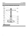
1
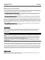
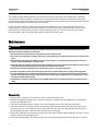
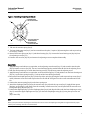
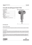
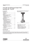
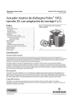
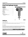
Instruction Manual 656 Actuator D100304X012 August 2012 Fisherr 656 Diaphragm Actuator Contents Figure 1. Fisher 656 Actuator Introduction . . . . . . . . . . . . . . . . . . . . . . . . . . . . . . . . . 1 Scope of Manual . . . . . . . . . . . . . . . . . . . . . . . . . . . . . 1 Description . . . . . . . . . . . . . . . . . . . . . . . . . . . . . . . . . 1 Principle of Operation . . . . . . . . . . . . . . . . . . . . . . . . . 2 Specifications . . . . . . . . . . . . . . . . . . . . . . . . . . . . . . . 2 Maximum Pressure Limitations . . . . . . . . . . . . . . . . 3 Installation . . . . . . . . . . . . . . . . . . . . . . . . . . . . . . . . . . 3 Adjustment . . . . . . . . . . . . . . . . . . . . . . . . . . . . . . . . . . 3 Maintenance . . . . . . . . . . . . . . . . . . . . . . . . . . . . . . . . . 4 Disassembly . . . . . . . . . . . . . . . . . . . . . . . . . . . . . . . . 4 Assembly . . . . . . . . . . . . . . . . . . . . . . . . . . . . . . . . . . . 5 Parts Ordering . . . . . . . . . . . . . . . . . . . . . . . . . . . . . . . . 7 Parts List . . . . . . . . . . . . . . . . . . . . . . . . . . . . . . . . . . . . 7 Handwheel Assembly . . . . . . . . . . . . . . . . . . . . . . . . 7 Casing-Mounted Adjustable Down Travel Stop . . . . . . . . . . . . . . . . . . . . . . . . . . . . . . 11 W0454 Introduction Scope of Manual This instruction manual includes installation, maintenance, and parts information for Fisher 656 diaphragm actuators. Refer to separate manuals for instructions covering the valve, positioner, and accessories. Description Fisher 656 actuators are long stroke, spring opposed, direct-acting diaphragm actuators. They operate Vee-Ballt control valves, butterfly valves, built-in turbine valves, louvers, dampers and similar equipment. They are suitable for either push-down-to-close (PDTC) or push-down-to-open (PDTO) applications and are available in sizes 30, 40 and 60 to provide 54 mm (2.125 inch), 64 mm (3.5 inch) and 105 mm (4.125 inch) travel, respectively. Do not install, operate, or maintain a 656 actuator without being fully trained and qualified in valve, actuator, and accessory installation, operation, and maintenance. To avoid personal injury or property damage, it is important to carefully read, understand, and follow all the contents of this manual, including all safety cautions and warnings. If you have any questions about these instructions, contact your Emerson Process Management sales office before proceeding. www.Fisher.com Instruction Manual 656 Actuator August 2012 D100304X012 Table 1. Specifications Maximum Recommended Casing Operating Pressure(1) 2.4 bar (35 psig) Casing Pressure Connection 1/4 NPT internal Maximum Travel Maximum Allowable Casing Pressure(2) 30 Maximum Casing Pressure for Actuator Sizing(2), Bar (Psig) 8.6 (125) 40 4.5 (65) 0.69 (10) 5.2 (75) 60 2.8 (40) 0.69 (10) 3.4 (50) Actuator Size MAXIMUM RATED STEM TRAVEL, mm (INCHES) Standard Optional Travel Travel Stop Stop 54 (2.125) Not available Maximum Excess Diaphragm Pressure(1), Bar (Psig) Maximum Diaphragm Casing Pressure(2,3), Bar (Psig) ACTUATOR SIZE 1.0 (15) 9.7 (140) 40 89 (3.5) 76 (3) 60 105 (4.125) 97 (3.8125) 1. Additional pressure may be added when the actuator is at full travel. If the Maxi mum Excess Diaphragm Pressure is exceeded, damage to the diaphragm or dia phragm casing might result. See the Maximum Pressure Limitation section. 2. Maximum diaphragm casing pressure must not be exceeded and must not produce a force on the actuator stem greater than the maximum allowable actuator output thrust or the maximum allowable stem load. See the Maximum Pressure Limitation section. 3. This maximum casing pressure is not to be used for normal operating pressure. Its purpose is to allow for typical regulator supply settings and/or relief valve tolerances. 30 Actuator Weight Actuator Size 30 Approximate Shipping Weight, kg (Pounds) 23 (50) 40 32 (70) 60 73 (160) Operating Temperature Range(3) J -40 to 82C (-40 to 180F) with Nitrile Elastomer J -40 to 149C (-40 to 300F) with Silicone Diaphragm Options J Top-mounted handwheel/adjustable travel stop J Casing-mounted adjustable down travel stop 1. Control and stability may be impaired if this pressure is exceeded. 2. Exceeding this pressure can cause damage to the diaphragm, diaphragm casing, or other parts. 3. The temperature limits in this manual and any applicable standard or code limitation for valve should not be exceeded. Principle of Operation In a direct acting diaphragm actuator, increasing loading pressure moves the actuator stem downward, compressing the spring. When the diaphragm pressure is decreased, the spring moves the actuator stem upward. In the event of failure of the loading pressure, the actuator stem moves to the extreme upward position. Specifications Refer to table 1 for Specifications of the 656 actuator. See the actuator nameplate for specific information for your actuator. WARNING To avoid personal injury or damage to equipment that may result in the malfunction of the control valve or loss of control of the process caused by excessive pressure, do not exceed the Maximum Pressures listed in table 1. Refer to the following Maximum Pressure Limitations section. 2 Instruction Manual D100304X012 656 Actuator August 2012 Maximum Pressure Limitations The casing and diaphragm of 656 actuators are pressure operated. This air pressure provides energy to compress the spring, to stroke the actuator, and to seat the valve. The following explanations describe the maximum pressure limits for an actuator. Refer to the nameplate or table 1 for maximum values for your actuator. D Maximum Casing Pressure for Actuator Sizing: This is the maximum pressure that can be applied at less than full travel of the actuator. If this stroking pressure is exceeded before the upper diaphragm plate contacts the travel stop, damage to the stem or other parts might result. D Maximum Excess Diaphragm Pressure: Additional pressure may be added when the actuator is at full travel. If the Maximum Excess Diaphragm Pressure is exceeded, damage to the diaphragm or diaphragm casing might result. Because the actuator has traveled its specified travel, and the diaphragm head is physically stopped from movement, the energy from any additional air pressure is transmitted to the diaphragm and diaphragm casings. The amount of air pressure that can be added once the actuator has traveled to the stops is limited by the resultant adverse effects that may occur. Exceeding this limiting factor could result in leakage or casing fatigue due to the deformation of the upper diaphragm casing. D Maximum Diaphragm Casing Pressure: If the Maximum Diaphragm Casing Pressure is exceeded, damage to the diaphragm, diaphragm casing, or actuator might result. Installation When an actuator and valve are shipped together, the actuator is normally mounted on the valve. Follow the valve instructions when installing the valve and actuator in a pipeline. If the actuator is shipped separately, or if it is necessary to mount the actuator on the valve, four holes have been tapped into the yoke boss to anchor it to a mounting bracket. WARNING Always wear protective gloves, clothing, and eyewear when performing any maintenance operations to avoid personal injury. To avoid personal injury or property damage caused by bursting of pressure retaining parts, be certain the diaphragm casing pressure does not exceed the limits listed in the Specifications table. Use pressure relieving or pressure limiting devices to prevent the diaphragm casing pressure from exceeding these limits. If installing into an existing application, also refer to the WARNING at the beginning of the Maintenance section in this instruction manual. To make the stem connection, follow the appropriate assembly step 10 in the Maintenance section. Standard actuator sizes 30 and 40 have mounting holes tapped 3/8 inch UNC, and the size 60 mounting holes are tapped 1/2 inch UNC. A 1/4 NPT loading pressure connection is located in the top of the upper diaphragm case. Using either pipe or tubing, connect either the loading pressure connection or valve positioner input connection (if a valve positioner is furnished, the loading pressure connection to the actuator will be made at the factory) to the output pressure connection on the controller. Keep the length of the pipe or tubing as short as possible to avoid transmission lag in the control signal. Adjustment When the actuator is completely installed and connected to the controller, it should be checked for correct travel, freedom from friction and correct PDTC or PDTO action. 3 656 Actuator Instruction Manual August 2012 D100304X012 The actuator spring and diaphragm have been selected to meet the requirements of the application. It should be noted that the actuator spring has a constant rate of compression and that adjustment of the spring compression merely shifts the initial spring setpoint up or down to make the actuator travel within the initial spring setpoint and the maximum diaphragm pressure indicated on the nameplate. In some instances, however, such as high friction butterfly and ball valves, the actuator will fully stroke with less diaphragm pressure than indicated on the nameplate. To increase the pressure required to initiate actuator stem movement, turn the lower bearing seat (key 14) up toward the spring case. To decrease the pressure at which movement begins, turn the lower bearing seat down, away from the spring case. Maintenance WARNING Avoid personal injury or property damage from sudden release of process pressure or uncontrolled movement of parts. Before performing any maintenance operations: D Do not remove the actuator from the valve while the valve is still pressurized. D Always wear protective gloves, clothing, and eyewear when performing any maintenance operations to avoid personal injury. D Disconnect any operating lines providing air pressure, electric power, or a control signal to the actuator. Be sure the actuator cannot suddenly open or close the valve. D Use bypass valves or completely shut off the process to isolate the valve from process pressure. Relieve process pressure from both sides of the valve. Drain the process media from both sides of the valve. D Vent the power actuator loading pressure and relieve any actuator spring precompression. D Use lock-out procedures to be sure that the above measures stay in effect while you are working on the equipment. D The valve packing box may contain process fluids that are pressurized, even when the valve has been removed from the pipeline. Process fluids may spray out under pressure when removing the packing hardware or packing rings, or when loosening the packing box pipe plug. D Check with your process or safety engineer for any additional measures that must be taken to protect against process media. Disassembly 1. If the actuator is installed on a control valve, isolate or bypass the control valve. 2. Shut off the diaphragm loading pressure and remove the pipe or tubing from the loading pressure connection in the top of the diaphragm case. 3. Turn the lower bearing seat (key 14) down, away from the spring case to relieve all spring compression. 4. If the entire actuator is to be removed from its mounting, disconnect the actuator stem (key 10) from the stem connector, clevis, etc., and remove the jam nuts (key 23). Loosen the cap screws that hold the yoke (key 9) to its mounting plate or bracket, and lift the entire actuator from its mounting. 5. Remove the diaphragm case cap screws and nuts (keys 19 and 20) and lift the upper diaphragm case (key 1 ) off the actuator. Remove the diaphragm (key 2). 6. Lift out the diaphragm plate (key 4) and stem (key 10). They may be separated by removing the cap screw (key 3). 4 Instruction Manual 656 Actuator D100304X012 August 2012 Figure 2. Travel Stop Orientation for Size 60 A MOUNTING BOSS ON ACTUATOR YOKE A A 11A0001-A LOCATE FOUR TRAVEL STOPS MARKED A MOUNTING BOX ON ACTUATOR YOKE 7. Take out the actuator spring (key 6). 8. The lower diaphragm case (key 5) can be removed from the yoke, if required, by loosening the travel stops and cap screws (keys 7 and 8). 9. Remove the lower spring seat (key 11) and thrust bearing (key 13). Unscrew the lower bearing seat (key 14) from the adjusting screw (key 12). 10. Remove the set screw (key 22) and remove the adjusting screw to complete disassembly. Assembly 1. Apply lithium grease lubricant, or equivalent, to the adjusting screw threads (key 12) and screw this into the yoke (key 9). Replace set screw (key 22). The set screw should engage the machined thread relief in the adjusting screw. 2. With the eared portion up, screw the lower bearing seat (key 14) all the way onto the adjusting screw. 3. Apply lithium grease lubricant, or equivalent, to the thrust bearing (key 13) and position it on the lower bearing seat (key 14). Lay the lower spring seat (key 11) on top of the thrust bearing assembly. 4. Mount the lower diaphragm case (key 5) to the top of the yoke (key 9) using the travel stops and cap screws (keys 7 and 8). Alternate screws and travel stops on the sizes 30 and 40. See figure 2 for the correct orientation of the size 60. 5. Position the actuator spring (key 6) on the lower spring seat. 6. Attach the diaphragm plate (key 4) to the actuator stem (key 10) with the cap screw (key 3). Apply lithium grease lubricant, or equivalent, to the stem. Place this assembly, actuator stem first, into the yoke with the actuator stem through the spring adjustor (key 12). 7. Position the diaphragm (key 2) on the diaphragm plate (key 4) and align the holes with the lower diaphragm casing (key 5). Attach the upper diaphragm case (key 1) to the lower diaphragm casing (key 5) using the cap screws and nuts (keys 19 and 20). Note When you replace actuator diaphragms in the field, take care to ensure the diaphragm casing bolts are tightened to the proper load to prevent leakage, but not crush the material. 5 656 Actuator August 2012 Instruction Manual D100304X012 Note Do not use lubricant on these bolts and nuts. Fasteners must be clean and dry. a. The first four bolts tightened should be diametrically opposed and 90 degrees apart. Tighten these four bolts to 13 NSm (10 lbfSft). b. Tighten the remaining bolts in a clockwise, criss-cross pattern to 13 NSm (10 lbfSft). c. Repeat this procedure by tightening four bolts, diametrically opposed and 90 degrees apart, to a torque of 27 NSm (20 lbfSft). d. Tighten the remaining bolts in a clockwise, criss-cross pattern to 27 NSm (20 lbfSft). e. After the last bolt is tightened to 27 NSm (20 lbfSft), all of the bolts should be tightened again to 27 NSm (20 lbfSft) in a circular pattern around the bolt circle. Once completed, no more tightening is recommended. 8. If the actuator has been removed from its mounting, position it on its mounting plate or bracket, and secure with cap screws. 9. Attach the pressure pipe or tubing to the loading pressure connection on top of the upper diaphragm case. 10. Attach the actuator stem to the stem connector or clevis and adjust the travel by using the appropriate procedure below. D For Push-Down-to-Open applications: 1. Set the controlled element (valve plug, louver, damper, etc.) in the closed position. 2. Turn the lower bearing seat (key 14) up toward the spring case far enough to ensure that the actuator stem is at the top of its stroke. 3. Make the actuator stem connection, making sure that there is full engagement of the actuator stem threads. Tighten slightly. 4. Apply loading pressure to the diaphragm case to move the controlled element toward its wide open position. Screw the controlled element linkage into the actuator stem connection far enough to move the controlled element toward its closed position 3.2 mm (1/8 inch), and tighten the stem connection securely. This adjustment ensures that the controlled element will close before the actuator stem travels to the top of its stroke. The travel stops (key 7) in the lower diaphragm case ensure correct travel of the controlled element in the open direction. 5. If travel starts at a lower or higher pressure than is required for proper operation, turn the lower bearing seat (key 14) up or down respectively, as described in the Adjustment section. D For Push-Down-to-Close applications: 1. Set the controlled element (valve plug, louver, damper, etc.) in the open position. 2. Turn the lower bearing seat (key 14) up toward the spring case far enough to ensure that the actuator stem is at the top of its stroke. 3. Tighten the actuator stem connection slightly, making sure that there is full engagement of the actuator stem threads. 4. Apply loading pressure to the diaphragm case and observe the travel of the controlled element to make sure that it closes completely. If the travel is not correct, it can be changed by screwing the controlled element linkage in or out of the stem connection. When the travel is set correctly, tighten the stem connection securely, and lock the jam nuts (key 23). 5. If travel starts at a lower or higher pressure than is required for proper operation, turn the lower bearing seat in or out respectively, as described in the Adjustment section. 6 Instruction Manual 656 Actuator D100304X012 August 2012 Parts Ordering When corresponding with your Emerson Process Management sales office about this equipment, refer to the serial number found on the actuator nameplate. WARNING Use only genuine Fisher replacement parts. Components that are not supplied by Emerson Process Management should not, under any circumstances, be used in any Fisher valve, because they may void your warranty, might adversely affect the performance of the valve, and could cause personal injury and property damage. Parts List Key 17 18 19 Note Part numbers are shown for recommended spares only. For Part numbers not shown, contact your Emerson Process Management sales office. Key 1 2* 3 4 5 6 7 8 9 10 11 12 13 14 Description 21 22 23 25 Part Number Nameplate, SST Drive Screw, SST (6 req'd) Cap Screw, steel Size 30 (12 req'd), Size 40 (16 req'd), Size 60 (24 req'd) Hex Nut, steel Size 30 (12 req'd), Size 40 (16 req'd), Size 60 (24 req'd) Valve Stem, 316 SST (Size 30 only) Set Screw, steel Hex Nut, steel (2 req'd) Warning Nameplate Part Number Diaphragm Case, steel Standard Diaphragm, Nitrile Size 30 2E791902202 Size 40 2E670002202 Size 60 2E859702202 Cap Screw, steel Diaphragm Plate, cast iron Lower Diaphragm Case, steel Actuator Spring, steel Down Travel Stop, steel Sizes 30 & 40 (3 req'd), Size 60 (4 req'd) Cap Screw, steel Sizes 30 & 40 (3 req'd), Size 60 (4 req'd) Yoke, cast iron Actuator Stem, steel Lower Spring Seat, steel Adjusting Screw, brass Thrust Bearing, steel ball bearing Lower Bearing Seat, steel *Recommended spare parts 20 Description Handwheel Assembly 51 54 133 135 137 138* Handwheel, cast iron Jam Nut, steel 1A353724122 Stem, brass Pusher Plate Assembly, steel Jam Nut, steel O-ring, nitrile Size 30 & 40 1D237506992 Size 60 1B885506992 139* O-ring, nitrile Size 30 & 40 1D267306992 Size 60 1D547106992 140 Groove Pin, steel 141 Cap Screw, steel Sizes 30 & 40 (6 req'd), Size 60 (8 req'd) 142 Handwheel body, cast iron 164 Body Extension, steel 171 Spacer, 416 SST (size 60 only) 7 Instruction Manual 656 Actuator August 2012 D100304X012 Figure 3. Fisher 656 Size 30 Actuator A APPLY THREAD LOCKING ADHESIVE (HIGH STRENGTH) TO SURFACE A CK1580 A0345-1 Figure 4. Fisher 656 Size 40 & 60 Actuators A B APPLY LITHIUM GREASE LUBRICANT ON SURFACES A & B 40A7798A 8 Instruction Manual D100304X012 656 Actuator August 2012 Figure 5. Typical Top-Mounted Handwheel Assembly for Diaphragm Actuator, Size 30 & 40 LUBRICATE END OF STEM AND PLATE WITH LITHIUM GREASE LUBRICATE STEM THREADS WITH ANTI-SEIZE LUBRICANT 38A1209-D 9 656 Actuator August 2012 Figure 6. Typical Top-Mounted Handwheel Assembly for Diaphragm Actuator, Size 60 LUBRICATE END OF STEM AND PLATE WITH LITHIUM GREASE LUBRICATE STEM THREADS WITH ANTI-SEIZE LUBRICANT 32B0262-B 10 Instruction Manual D100304X012 Instruction Manual 656 Actuator D100304X012 August 2012 Figure 7. Casing-Mounted Adjustable Down Travel Stop for Size 30 and 40 Actuators (Style 2) APPLY LUB BV8054-D Casing-Mounted Adjustable Down Travel Stop (figure 7) Key Description 54 133 134 Stop Nut Travel Stop Stem Washer *Recommended spare parts Key Part Number Description 139* O-Ring, nitrile Sizes 30, 34, & 40 Sizes 45, 46, 50, & 60 Sizes 70 & 87 141 Cap Screw 142 Body 187 Travel Stop Cap 189 Jam Nut 241 Lubricant, Lithium Grease or equivalent (not furnished with travel stop) Part Number 1D267306992 1D547106992 1D269106992 11 656 Actuator August 2012 Instruction Manual D100304X012 Neither Emerson, Emerson Process Management, nor any of their affiliated entities assumes responsibility for the selection, use or maintenance of any product. Responsibility for proper selection, use, and maintenance of any product remains solely with the purchaser and end user. Fisher and Vee-Ball are marks owned by one of the companies in the Emerson Process Management business unit of Emerson Electric Co. Emerson Process Management, Emerson, and the Emerson logo are trademarks and service marks of Emerson Electric Co. All other marks are the property of their respective owners. The contents of this publication are presented for informational purposes only, and while every effort has been made to ensure their accuracy, they are not to be construed as warranties or guarantees, express or implied, regarding the products or services described herein or their use or applicability. All sales are governed by our terms and conditions, which are available upon request. We reserve the right to modify or improve the designs or specifications of such products at any time without notice. Emerson Process Management Marshalltown, Iowa 50158 USA Sorocaba, 18087 Brazil Chatham, Kent ME4 4QZ UK Dubai, United Arab Emirates Singapore 128461 Singapore www.Fisher.com 12 E 1974, 2012 Fisher Controls International LLC. All rights reserved.