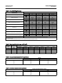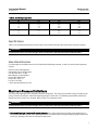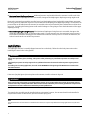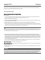
1
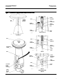
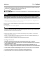
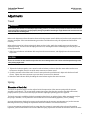
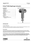
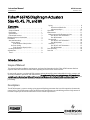
Instruction Manual 667NS Actuator D102603X012 November 2012 Fisherr 667NS Diaphragm Actuators Size 40, 45, 70, and 80 Contents Introduction . . . . . . . . . . . . . . . . . . . . . . . . . . . . . . . . . Scope of Manual . . . . . . . . . . . . . . . . . . . . . . . . . . . . . Description . . . . . . . . . . . . . . . . . . . . . . . . . . . . . . . . . Specifications . . . . . . . . . . . . . . . . . . . . . . . . . . . . . . . Educational Services . . . . . . . . . . . . . . . . . . . . . . . . . Maximum Pressure Limitations . . . . . . . . . . . . . . . . . . Installation . . . . . . . . . . . . . . . . . . . . . . . . . . . . . . . . . . Actuator Mounting . . . . . . . . . . . . . . . . . . . . . . . . . . Direct-Acting (Push-Down-to-Close) Valves . . . . . . . . . . . . Reverse-Acting (Push-Down-to-Open) Valves . . . . . . . . . . . . Loading Connection . . . . . . . . . . . . . . . . . . . . . . . . . . Adjustments . . . . . . . . . . . . . . . . . . . . . . . . . . . . . . . . . Travel . . . . . . . . . . . . . . . . . . . . . . . . . . . . . . . . . . . . . . 1 1 1 3 3 3 4 5 5 6 8 9 9 Spring . . . . . . . . . . . . . . . . . . . . . . . . . . . . . . . . . . . . . 9 Discussion of Bench Set . . . . . . . . . . . . . . . . . . . 9 Adjustment Steps . . . . . . . . . . . . . . . . . . . . . . . 10 Operation . . . . . . . . . . . . . . . . . . . . . . . . . . . . . . . . . . 11 Maintenance . . . . . . . . . . . . . . . . . . . . . . . . . . . . . . . . 11 Replacement of the Elastomeric Parts . . . . . . . . . . 12 Size 40, 45, and 70 Actuators . . . . . . . . . . . . . 12 Size 80 Actuators . . . . . . . . . . . . . . . . . . . . . . . 13 Disassembly . . . . . . . . . . . . . . . . . . . . . . . . . . . . . . . 14 Size 40, 45, and 70 Actuators . . . . . . . . . . . . . 14 Size 80 Actuators . . . . . . . . . . . . . . . . . . . . . . . 14 Assembly . . . . . . . . . . . . . . . . . . . . . . . . . . . . . . . . . . 15 Size 40, 45, and 70 Actuators . . . . . . . . . . . . . 15 Size 80 Actuators . . . . . . . . . . . . . . . . . . . . . . . 16 Parts Ordering . . . . . . . . . . . . . . . . . . . . . . . . . . . . . . . 18 Parts List . . . . . . . . . . . . . . . . . . . . . . . . . . . . . . . . . . . 18 Introduction Scope of Manual This manual provides installation, maintenance, and parts list information for the Fisher 667NS actuator. Refer to separate instruction manuals for information regarding the control valve and accessories. Do not install, operate, or maintain 667NS actuators without being fully trained and qualified in valve, actuator, and accessory installation, operation, and maintenance. To avoid personal injury or property damage, it is important to carefully read, understand, and follow all the contents of this manual, including all safety cautions and warnings. If you have any questions about these instructions, contact your Emerson Process Management sales office before proceeding. Description The 667NS actuator is a reverse-acting, spring-opposed diaphragm actuator that is used for operation of automatic control valves. The 667NS actuator yoke construction and special bonnet-to-yoke bolting provides a high structural resonant frequency that exceeds most nuclear service seismic requirements. www.Fisher.com Instruction Manual 667NS Actuator November 2012 D102603X012 Table 1. Fisher 667NS Specifications ACTUATOR SIZE SPECIFICATION Nominal Effective Diaphragm Area Yoke Boss Diameters Acceptable Valve Stem Diameters 40 45 70 80 cm2 445 677 1419 see table 5 Inch2 69 105 220 see table 5 mm 71 71 90 5H Inch 2-13/16 2-13/16 3-9/16 5H mm 12.7 12.7 19.1 25.4 & 31.8 Inch 1/2 1/2 3/4 1 & 1-1/4 N 12,015 30,371 42,720 88,110 Lb 2700 6825 9600 19,800 mm 38 51 76 76 Inch 1.5 2 3 3 Bar 4.5 4.5 3.5 4.8 Maximum Allowable Output Thrust(1) Maximum Travel Maximum Diaphragm Pressure to Stroke Actuator(2,3) Maximum Excess Diaphragm Pressure(2,3) Maximum Casing Pressure for Actuator Sizing(3) Maximum Diaphragm Casing Pressure(2,3) Psig 65 65 50 70 Bar 3.1 2.1 1.0 1.4 Psig 45 30 15 20 Bar 4.8 4.5 3.4 4.9 Psig 70 65 50 70 Bar 6.2 5.2 4.1 5.5 Psig 90 75 60 80 Material Temperature Capabilities(3) -40 to 82_C (-40 to 180_F) with nitrile diaphragm 1. See also the Specifications portion of the Introduction section. Do not exceed maximum allowable valve stem load when applying maximum allowable thrust. 2. Maximum diaphragm casing pressure must not be exceeded and must not produce a force on the actuator stem greater than the maximum allowable actuator output thrust or the maxi mum allowable stem load. 3. The pressure and temperature limitations in this manual, and any applicable code limitation, should not be exceeded. Table 2. Diaphragm Casing Volumes, cm3 (Inch3) 11 (0.4375) 16 (0.625) 19 (0.75) 29 (1.125) 38 (1.5) 51 (2) 76 (3) 40 CLEARANCE VOLUME, cm3 (INCH3) 934 (57) 1475 (90) 1704 (104) 1852 (113) 2327 (142) 2786 (170) --- --- 45 1556 (95) --- 2786 (170) 2999 (183) 3720 (227) 4424 (270) 5408 (330) --- 70 3490 (213) 5244 (320) 5948 (363) 6424 (392) 7833 (478) 9242 (564) 11,110 (678) 14,879 (908) 80 4818 (294) --- --- --- 10,488 (640) 12,454 (760) 14,863 (907) 19,337 (1180) ACTUATOR SIZE TRAVEL, mm (INCH) Table 3. Actuator Stem Assembly Bolt Torque Values ACTUATOR SIZE 40 45 70 80 TORQUE NSm LbfSFt 68 183 183 542 50 135 135 400 Table 4. Bonnet-to-Actuator Bolt Torque Values ACTUATOR SIZE 40 45 70 80 2 BONNET-ACTUATOR STUD BOLT TORQUE NSm LbfSFt 102 102 176 292 75 75 130 215 Instruction Manual 667NS Actuator D102603X012 November 2012 Table 5. Size 80 Diaphragm Area TRAVEL AREA mm Inch cm2 Inch2 0 19 29 38 0 0.75 1.125 1.5 2039 1903 1865 1845 316 295 289 286 51 64 76 2 2.5 3 1832 1800 1761 284 279 273 Specifications Tables 1 and 2 provide specifications for the various sizes of 667NS actuators discussed in this instruction manual. WARNING To avoid personal injury or property damage, do not exceed pressure and temperature limits specified in table 1. Educational Services For information on available courses for the Fisher 667NS diaphragm actuator, as well as a variety of other products, contact: Emerson Process Management Educational Services, Registration P.O. Box 190; 301 S. 1st Ave. Marshalltown, IA 50158-2823 Phone: 800-338-8158 or Phone: 641-754-3771 FAX: 641-754-3431 e-mail: [email protected] Maximum Pressure Limitations The casing and diaphragm of 667 actuators are pressure operated. This air pressure provides energy to compress the spring, to stroke the actuator, and lift the diaphragm away from the valve. The following explanations describe the maximum pressure limits for an actuator. Refer to table 1 for maximum values. WARNING To avoid personal injury or property damage, do not exceed pressure and temperature limits specified in table 1. D Maximum Diaphragm Pressure to Stroke the Actuator: This is the maximum pressure that can be applied at less than full travel of the actuator. If this stroking pressure is exceeded before the upper diaphragm plate contacts the travel stop, damage to the stem or other parts might result. 3 667NS Actuator November 2012 Instruction Manual D102603X012 D Maximum Excess Diaphragm Pressure: Additional pressure may be added when the actuator is at full travel. If the Maximum Excess Diaphragm Pressure is exceeded, damage to the diaphragm or diaphragm casing might result. Because the actuator has traveled its specified travel, and the diaphragm head is physically stopped from movement, the energy from any additional air pressure is transmitted to the diaphragm and diaphragm casings. The amount of air pressure that can be added once the actuator has traveled to the stops is limited by the resultant adverse effects that may occur. Exceeding this limiting factor could result in leakage or casing fatigue due to the deformation of the upper diaphragm casing. D Maximum Diaphragm Casing Pressure: If the Maximum Diaphragm Casing Pressure is exceeded, damage to the diaphragm, diaphragm casing, or actuator might result. For some actuator sizes, the maximum casing pressure is the sum of the maximum stroking pressure added to the maximum excess pressure. For other actuator sizes, the value is lower than the sum of the two pressures. Installation The diaphragm actuator is normally shipped mounted on a valve body. Follow the valve body instructions when installing the control valve in the pipeline. WARNING Always wear protective gloves, clothing, and eyewear when performing any installation operations to avoid personal injury. Check with your process or safety engineer for any additional measures that must be taken to protect against process media. If installing into an existing application, also refer to the WARNING at the beginning of the Maintenance section in this instruction manual. If the cover (key 84, figure 4) is not in place on the actuator, install it as shown in figure 4. WARNING If the control valve and actuator are installed with the actuator in any position other than vertical, the actuator may not conform with safety-related qualifications. Nonvertical orientation should be part of existing qualification analysis on file at the plant site to ensure conformance with safety-related qualifications. The control valve assembly may be installed with any orientation; however, the actuator should not be installed in ways that allow water to collect in the yoke and actuator spring areas. Note The 667NS actuator will not mount on a standard valve bonnet; it requires a style NS bonnet having eight bonnet-to-yoke stud bolts. 4 Instruction Manual D102603X012 667NS Actuator November 2012 If the actuator and control valve body are separate, mount the 667NS actuator on the valve body by following the procedures in the Actuator Mounting section of this manual. Actuator Mounting Direct-Acting (Push-Down-to-Close) Valves Refer to figure 1. 1. Screw the stem locknuts all the way onto the valve stem. Put the travel indicator disk, not used with the size 80 actuator, on the locknuts. The concave side of the disk should face the valve. 2. Place the actuator on the valve bonnet. 3. Insert the cap screws and tighten the hex nuts (not shown), securing the actuator to the bonnet. Tighten the cap screws to the torque shown in table 4. 4. Apply loading pressure to the actuator to retract the actuator stem fully (against the travel stop). 5. With the travel indicator scale attached to the actuator yoke, make a temporary mark on the actuator stem in line with the top mark on the scale (the mark on the end of the scale that is marked “OPEN”). (The distance from the top mark on the scale to the bottom mark is equal to the travel of the valve.) Note Before turning the spring adjuster on size 70 or 80 actuators, assemble the stem connector around the actuator stem and the anti-rotating lug on the yoke. Mark the actuator stem as a visual reference to verify that stem rotation does not occur. Remove the stem connector before rechecking the bench set. 6. Refer to the actuator nameplate to determine the bench set pressure range of the actuator. Reduce actuator loading pressure to the lower end of the bench set range. (For size 80, remove the cap screw (key 91, figure 4) and remove the adjusting screw cover (key 84, figure 4). Rotate the spring adjustor (key 74, figure 2 for sizes 40 and 45; key 74, figure 3 for size 70; and key 74, figure 4 for size 80) until the mark you made on the actuator stem is in line with the bottom mark on the travel indicator scale. (Replace the size 80 adjusting screw cover and cap screw when you have completed the adjustments.) 7. Increase actuator loading pressure to the upper end of the bench range and check to be sure that the mark on the actuator stem is in line with the top mark on the travel indicator scale. If the marks are in line, the actuator is properly bench set. If the marks are not in line, the spring is not correct for the specified bench set. It is necessary to use a different spring or a different bench set. 8. Reduce actuator loading pressure until the mark on the actuator stem is in line with the bottom mark on the travel indicator scale. CAUTION Do not clamp just the tip of either the valve stem or the actuator stem in the stem connector. Incomplete engagement of the valve stem and/or actuator stem in the stem connector might result in stripped threads or improper operation. Be sure that the length of each stem clamped in the stem connector is equal to or greater than the diameter of that stem. 5 667NS Actuator November 2012 Instruction Manual D102603X012 9. Push the valve stem firmly against its seat, and be sure that it remains firmly against the seat. Clamp the actuator stem and valve stem between the two stem connector halves. If necessary, increase actuator loading pressure slightly to allow the valve stem, actuator stem, and stem connector threads to match. Insert and tighten the stem connector cap screws. WARNING To avoid personal injury due to the sudden, uncontrolled movement of parts, do not loosen the cap screws when the stem connector has spring or loading pressure force applied to it. 10. Raise the travel indicator disk (sizes 40 through 70 only) to the stem connector. For all sizes, thread the stem locknuts against the stem connector. 11. Remove all actuator loading pressure. Move the travel indicator scale so that the indicator disk (or pointer) is in line with the bottom mark of the travel indicator scale. 12. Check the valve travel to be sure that the valve travels fully with no overtravel. Reverse-Acting (Push-Down-to-Open) Valves Refer to figure 1. 1. Screw the stem locknuts all the way onto the valve stem. Put the travel indicator disk, not used with the size 80 actuator, on the locknuts. The concave side of the disk should face the valve. 2. Place the actuator on the valve bonnet. 3. Insert the cap screws and tighten the hex nuts (not shown), securing the actuator to the bonnet. Tighten the cap screws to the torque in table 4. Note Before turning the spring adjuster on size 70 or 80 actuators, assemble the stem connector around the actuator stem and the anti-rotating lug on the yoke. Mark the actuator stem as a visual reference to verify that stem rotation does not occur. Remove the stem connector before rechecking the bench set. 4. (For size 80, remove the cap screw (key 91, figure 4) and remove the adjusting screw cover (key 84, figure 4). Rotate the spring adjustor (key 74, figure 2 for sizes 40 and 45; key 74, figure 4 for size 70; and key 74, figure 4 for size 80) to position the actuator stem at its fully extended position. 5. With the travel indicator scale attached to the actuator yoke, make a temporary mark on the actuator stem in line with the bottom mark on the scale (the mark on the end of the scale that is marked “OPEN”). (The distance from the bottom mark on the scale to the top mark is equal to the travel of the valve.) 6. Refer to the actuator nameplate to determine the bench set pressure range of the actuator. Apply an actuator loading pressure to the actuator equal to the lower end of the bench set range and rotate the spring adjustor until the mark you made on the actuator stem is in line with the bottom mark on the travel indicator scale. (Replace the size 80 adjusting screw cover and cap screw when you have completed the adjustments.) 6 Instruction Manual 667NS Actuator D102603X012 November 2012 Figure 1. Schematic and Stem Connection Details for Fisher 667NS SPRING PUSHES DOWN AIR LIFTS SPRING ADJUSTOR YOKE STEM CONNECTOR TRAVEL INDICATOR TRAVEL INDICATOR DISK STEM LOCKNUTS SIZES 40 AND 45 VALVE STEM 55A9191-H A3833-A SCHEMATIC VENT YOKE SPRING ADJUSTOR TRAVEL INDICATOR DIAPHRAGM CASING TRAVEL INDICATOR DISK STEM LOCKNUTS VALVE STEM 55A9193-F SIZE 70 YOKE TRAVEL INDICATOR POINTER TRAVEL INDICATOR STEM CONNECTOR YOKE ACTUATOR VALVE STUDS AND NUTS STEM LOCKNUTS 56A1032-D FISHER DBQ-NS VALVE VALVE STEM SIZE 80 STEM CONNECTION DETAILS A5958/MM1 C0762-1 7 667NS Actuator Instruction Manual November 2012 D102603X012 7. Increase actuator loading pressure to the upper end of the bench range and check to be sure that the mark on the actuator stem is in line with the top mark on the travel indicator scale. If the marks are in line, the actuator is properly bench set. If the marks are not in line, the spring is not correct for the specified bench set. It is necessary to use a different spring or a different bench set. CAUTION Do not clamp just the tip of either the valve stem or the actuator stem in the stem connector. Incomplete engagement of the valve stem and/or actuator stem in the stem connector might result in stripped threads or improper operation. Be sure that the length of each stem clamped in the stem connector is equal to or greater than the diameter of that stem. 8. Pull the valve stem firmly against its seat, and be sure that it remains firmly against the seat. Clamp the actuator stem and valve stem between the two stem connector halves. If necessary, decrease actuator loading pressure slightly to allow the valve stem, actuator stem, and stem connector threads to match. Insert and tighten the stem connector cap screws. WARNING To avoid personal injury due to the sudden uncontrolled movement of parts, do not loosen the cap screws when the stem connector has spring or loading pressure force applied to it. 9. Raise the travel indicator disk to the stem connector (sizes 40 through 70 only). For all sizes, thread the stem locknuts against the stem connector. 10. Remove all actuator loading pressure. Move the travel indicator scale so that the indicator disk (or pointer) is in line with the bottom mark of the travel indicator scale. 11. Check the valve travel to be sure that the valve travels fully with no overtravel. Loading Connection 1. Connect the loading pressure piping to the NPT internal connection in the top of the actuator yoke. 2. For size 70 actuators, remove the 1/4-inch bushing in the 1/2 NPT internal connection to increase connection size, if necessary. Use either piping or tubing. 3. Keep the length of tubing or piping as short as possible to avoid transmission lag in the control signal. If an accessory (such as a volume booster or valve positioner) is used, be sure that the accessory is properly connected to the actuator. Refer to the positioner instruction manual if necessary. 4. Cycle the actuator several times to check that the valve stem travel is correct and that the travel occurs when the correct pressure range is applied to the diaphragm. 5. If valve stem travel is incorrect, refer to the Travel procedure in the Adjustments section. 6. If the pressure range is incorrect, refer to the Spring procedure in the Adjustments section. 8 Instruction Manual D102603X012 667NS Actuator November 2012 Adjustments Travel WARNING When moving the actuator stem with diaphragm loading pressure, use caution to keep hands and tools out of the actuator stem travel path. Personal injury and/or property damage is possible if something is caught between the actuator stem and other control valve assembly parts. Make travel adjustments when the motion observed during actuator travel is different from the travel stamped on the actuator nameplate. If the Actuator Mounting procedure was followed correctly, this adjustment should not be necessary. When adjusting travel of a direct-acting (push-down-to-close) valve, apply a low supply pressure to the actuator diaphragm casing. This moves the valve plug off of the seat, reducing the chance of damaging the valve plug or seat during adjustments. 1. Back the stem locknuts and indicator disk away from the stem connector, and slightly loosen the stem connector cap screws. CAUTION Do not use wrenches or other tools directly on the valve stem. Damage to the stem surface and subsequent damage to the valve packing might result. 2. Tighten the locknuts together, use a wrench on these locknuts, and screw the valve stem either into the stem connector to lengthen travel or out of the stem connector to shorten travel. 3. Cycle the actuator to check the travel. If travel is not equal to the specified travel, adjust and check travel until correct. Tighten the stem connector cap screws when correct travel is obtained. 4. Raise the travel indicator disk by threading the stem locknuts against the stem connector. Spring Discussion of Bench Set The bench set pressure range is used to adjust the initial compression of the actuator spring with the actuator assembly “on the bench”. The correct initial compression ensures that the valve-actuator assembly will function properly when it is put in service and the proper actuator diaphragm operating pressure is applied. The bench set range is established with the assumption that there is no packing friction. When attempting to adjust the spring in the field, it is very difficult to ensure that there is no friction being applied by “loose” packing. Accurate adjustment to the bench set range can be made during the actuator mounting process (see the Actuator Mounting Procedure) by making the adjustment before the actuator is connected to the valve. If you are attempting to adjust the bench set range after the actuator is connected to the valve and the packing tightened, you must take friction into account. Make the spring adjustment such that full actuator travel occurs at the 9 Instruction Manual 667NS Actuator November 2012 D102603X012 bench set range (a) plus the friction force divided by the effective diaphragm area with increasing diaphragm pressure or (b) minus the friction force divided by the effective diaphragm area with decreasing diaphragm pressure. For an assembled valve-actuator assembly, determine valve friction as described below: 1. Install a pressure gauge in the actuator loading pressure line that connects to the actuator diaphragm casing. Note Steps 2 and 4 require that you read and record the pressure shown on the pressure gauge. 2. Increase the actuator diaphragm pressure and read the diaphragm pressure as the actuator reaches its mid-travel position. 3. Increase the actuator diaphragm pressure until the actuator is at a travel position greater than its mid-travel position. 4. Decrease the actuator diaphragm pressure and read the diaphragm pressure as the actuator reaches its mid-travel position. The difference between the two diaphragm pressure readings is the change in the diaphragm pressure required to overcome the friction forces in the two directions of travel. 5. Calculate the actual friction force: ( Friction Force, =1/2 pounds )( Difference in pressure readings, psig X ) Effective diaphragm area, inches 2 Refer to table 1 and 5 for the effective diaphragm area. When determining valve friction, you can make diaphragm pressure readings at a travel position other than mid-travel if you desire. If you take readings at the zero or at the full travel position, take extra care to ensure that the readings are taken when the travel just begins or just stops at the position selected. It is difficult to rotate the spring adjustor (key 74, figure 2, 3, or 4) when the full actuator loading pressure is applied to the actuator. Release the actuator loading pressure before adjusting. Then re-apply loading pressure to check the adjustment. Adjustment Steps 1. Monitor actuator loading pressure carefully when making adjustments. Do not exceed the maximum pressure specifications of either the loading regulator or the actuator casings (refer to table 1 for maximum diaphragm casing pressure). 2. Each actuator spring has a fixed pressure span. Changing the spring compression shifts the span up or down to make valve travel coincide with the pressure range. Note Before turning the spring adjuster on size 70 or 80 actuators, assemble the stem connector around the actuator stem and the anti-rotating lug on the yoke. Mark the actuator stem as a visual reference to verify that stem rotation does not occur. Remove the stem connector before rechecking the bench set. 10 Instruction Manual D102603X012 667NS Actuator November 2012 3. For sizes 40 through 70, turn the spring adjustor (key 74, figure 2 or 3) into the yoke to shift the span up or turn the spring adjustor out of the yoke to shift the span down. For size 80, remove the cap screw (key 91, figure 4) and remove the adjusting screw cover (key 84); then rotate the spring adjustor (key 74) to shift the span. Replace the cover and cap screw when adjustment is complete. If the actuator has a side-mounted handwheel assembly (manual actuator), clockwise handwheel rotation closes the valve. For successful operation, the actuator stem and valve plug stem must move freely in response to the loading pressure change on the diaphragm. Operation In a reverse-acting diaphragm actuator, an increasing loading pressure causes the actuator stem to move upward, compressing the spring. When the diaphragm pressure is decreased, the spring moves the actuator stem downward. This is shown graphically in figure 1. In the event of failure of the loading pressure to the diaphragm of the actuator, the actuator stem moves to the extreme downward position. Thus, by the proper selection of the valve plug action, either push-down-to-close or push-down-to-open, the control valve will either close or open on failure of the diaphragm loading pressure. The nameplate attached to the yoke of the actuator provides information about the specific construction and operating range. The spring and diaphragm have been selected to meet the requirements of the application, and in service, the actuator should create full travel of the valve plug when the diaphragm pressure (operate) range indicated on the nameplate is applied. This diaphragm pressure range is generally 0.2 to 1.0 bar or 0.4 to 2.0 bar (3 to 15 psi or 6 to 30 psi). Pressure in the valve body creates a force on the valve plug that has a direct effect on the actual operating diaphragm pressure range. In some instances, the valve may not stroke completely over the indicated range because the pressure conditions in the body are different from those for which the control valve has been set at the factory. A simple spring adjustment, however, may be all that is required to obtain correct travel for the diaphragm pressure range utilized. Note that the actuator spring has a fixed pressure span and that adjustment of the spring compression merely shifts this span up or down to make valve travel coincide with the diaphragm pressure range. The nameplate specifies a bench set pressure range in addition to a diaphragm pressure (operate) range. The bench set range is that pressure range required to stroke the valve fully without any pressure in the body, as would be the case if the valve were set on the work bench. However, in service with the specified pressure drop applied across the valve, it should stroke over that diaphragm pressure (operate) range indicated on the nameplate. When the control valve and actuator are installed, the actuator should be checked for correct travel, freedom from excessive friction, and correct action (air-to-open or air-to-close) to match the controlling instrument. For successful operation, the actuator stem and valve plug stem must move freely in response to the loading pressure change on the diaphragm. Maintenance Normally, only the elastomeric parts and the spring of the 667NS actuator require inspection or replacement. The maintenance instructions are divided into three subsections: Replacement of Elastomeric Parts, Disassembly, and Assembly. Perform only those steps applicable to the actuator size and required maintenance. It is recommended that the diaphragm and all of the other elastomeric parts of the 667NS actuator be inspected every two years. The absolute maximum replacement period for any of the elastomeric parts is four years. 11 667NS Actuator Instruction Manual November 2012 D102603X012 All maintenance operations can be performed with the valve in the line. WARNING Avoid personal injury or property damage from sudden release of process pressure or bursting of parts. Before performing any maintenance operations: D Do not remove the actuator from the valve while the valve is still pressurized. D Always wear protective gloves, clothing, and eyewear when performing any maintenance operations to avoid personal injury. D Disconnect any operating lines providing air pressure, electric power, or a control signal to the actuator. Be sure the actuator cannot suddenly open or close the valve. D Use bypass valves or completely shut off the process to isolate the valve from process pressure. Relieve process pressure from both sides of the valve. Drain the process media from both sides of the valve. D Vent the power actuator loading pressure and relieve any actuator spring precompression. D Use lock-out procedures to be sure that the above measures stay in effect while you work on the equipment. D The valve packing box may contain process fluids that are pressurized, even when the valve has been removed from the pipeline. Process fluids may spray out under pressure when removing the packing hardware or packing rings, or when loosening the packing box pipe plug. D Check with your process or safety engineer for any additional measures that must be taken to protect against process media. Replacement of Elastomeric Parts Size 40, 45, and 70 Actuators Perform the following if you are replacing only the elastomeric parts of the 667NS actuator, and no other maintenance is necessary. The diaphragm, the gasket, and the seal bushing O-rings are the only elastomeric parts in the size 40, 45, and 70 actuators. Key number references are shown in figure 2 for size 40 and 45 actuators and in figure 3 for size 70 actuators. 1. Isolate the control valve from the line pressure, release pressure from both sides of the valve body, and drain the process media from both sides of the valve. Reduce the actuator loading pressure to atmospheric pressure. 2. Remove the diaphragm casing cap screws and nuts (keys 13 and 14), and lift off the upper diaphragm casing (key 1). CAUTION Do not allow the valve stem to rotate during this operation since it could cause damage to the valve seats. 3. Remove the diaphragm plate cap screw and spacer (key 12 and 2). For actuator sizes 40 and 45, place a wrench on the actuator-valve stem connector assembly (key 31) to prevent the actuator stem (key 144) from rotating during the loosening of the diaphragm plate cap screw (key 12). 4. Take out the diaphragm (key 3), the upper diaphragm plate (key 4), and the lower diaphragm plate (key 71). 5. Remove the snap ring (key 72), and pull out the seal bushing (key 7). The seal bushing has two 1/4-20 UNC tapped holes provided in its top surface to be used as an aid in removing it. 12 Instruction Manual 667NS Actuator D102603X012 November 2012 6. Install three new O-rings (keys 8 and 9) on the seal bushing. 7. Lubricate the O-rings, and fill the seal bushing with lithium grease (key 99) or high-temperature, radiation-resistant, polyphenyl ether grease (key 100), as appropriate to the installation and install the bushing in the top of the actuator yoke assembly (key 73). Secure with the snap ring. 8. Coat a new gasket (key 70) with lithium grease (key 99) or high-temperature, radiation-resistant, polyphenyl ether grease (key 100), as appropriate to the installation, and place the gasket on the yoke (key 73). Assemble the lower diaphragm plate, the new diaphragm, and the upper diaphragm plate onto the actuator stem. CAUTION Do not allow the valve stem to rotate during this operation because it could cause damage to the valve seats. 9. Install the diaphragm plate cap screw and spacer. Tighten the cap screw to the torque value indicated in table 3. For actuator sizes 40 and 45, place a wrench on the actuator valve stem connector assembly to prevent the actuator stem from rotating during the tightening of the diaphragm plate cap screw. Note When you replace actuator diaphragms in the field, take care to ensure the diaphragm casing bolts are tightened to the proper load to prevent leakage, but not crush the material. Perform the following tightening sequence with a manual torque wrench for size 40, 45, and 70 actuators. CAUTION Overtightening the diaphragm casing cap screws and nuts (keys 13 and 14) can damage the diaphragm. Do not exceed a torque of 27 NSm (20 lbfSft) when performing the following tightening procedure. Note Do not use lubricant on these cap screws and nuts. Fasteners must be clean and dry. 10. Place the upper diaphragm casing into position, and replace the diaphragm casing cap screws and nuts. Tighten in the following manner. The first four hex nuts tightened should be diametrically opposed and 90 degrees apart. Tighten these four hex nuts to 13 NSm (10 lbfSft). 11. Tighten the remaining hex nuts in a clockwise, criss-cross pattern to 13 NSm (10 lbfSft). 12. Repeat this procedure by tightening four hex nuts, diametrically opposed and 90 degrees apart, to a torque of 27 NSm (20 lbfSft). 13. Tighten the remaining hex nuts in a clockwise, criss-cross pattern to 27 NSm (20 lbfSft). 14. After the last hex nut is tightened to 27 NSm (20 lbfSft), all of the hex nuts should be tightened again to 27 NSm (20 lbfSft) in a circular pattern around the bolt circle. 15. Once completed, no more tightening is recommended. Size 80 Actuators The elastomeric parts in a size 80 actuator include the diaphragm and O-rings. Since replacement of these parts necessitates complete disassembly, perform the steps outlined in the procedures for disassembly and assembly of size 80 actuators. 13 667NS Actuator November 2012 Instruction Manual D102603X012 Disassembly Size 40, 45, and 70 Actuators Key number references are shown in figure 2 for size 40 and 45 actuators and in figure 3 for size 70 actuators. 1. Bypass the control valve. Reduce the actuator loading pressure to atmospheric pressure, and remove the tubing or piping from the connection in the yoke cap (key 239). 2. To aid in assembly, record the position of the spring adjustor (key 74) on the actuator stem (key 144). Loosen the spring adjustor jam nut (key 102), and thread the spring adjustor jam nut and the spring adjustor off the actuator stem until all spring compression is relieved. 3. Remove the entire actuator from the valve body by removing the two cap screws from the stem connector assembly (key 31), separating the two halves of the stem connector and removing the eight bonnet stud bolt nuts. 4. Thread the spring adjustor jam nut and the spring adjustor off the actuator stem. Remove the spring seat (key 19). 5. Remove the diaphragm casing cap screws and nuts (key 13 and 14), and lift off the upper diaphragm casing (key 1). 6. Take out the diaphragm (key 3), the upper diaphragm plate (key 4), the lower diaphragm plate (key 71), and the actuator stem as an assembly. Use care when pulling the threads of the actuator stem through the seal bushing (key 7) to avoid damaging the O-rings (key 8). 7. Remove the diaphragm plate cap screw and spacer (keys 12 and 2) to separate the parts of this assembly. 8. Remove the snap ring (key 72), and lift out the seal bushing (key 7). Remove and check the O-rings (keys 8 and 9) for excessive wear or damage. 9. Remove the cap screws (key 30), and take off the lower diaphragm casing (key 64), the gasket (key 70), and the yoke cap. Lift out the spring (key 18). Size 80 Actuators Key number references are shown in figure 4. 1. Remove the cap screws (key 91) and the adjusting screw cover (key 84). 2. Unscrew the hex nuts (keys 85 and 86) from the actuator stem (key 93). Record the position of the spring adjustor (key 74) relative to the spring case (key 92). Loosen the spring adjustor locknut (key 90), and unscrew the spring adjustor, relieving all compression from the spring (key 18). 3. Remove the two cap screws from the stem connector assembly (key 31), and separate the stem connector halves. 4. If removal of the actuator is necessary, unbolt the eight bonnet stud bolt nuts, and remove the actuator from the valve body. Otherwise, leave the actuator mounted on the valve body. 5. Unscrew the cap screws and nuts (keys 13 and 14), and lift the upper diaphragm casing and spring case assembly (keys 1 and 92) over the spring. 6. Remove the spring seat (key 19), the bearing race and bearing (keys 88 and 89), and the guide bushing (key 97). 7. Lift off the spring. 8. Remove the actuator stem with the attached hex nuts (key 94), the diaphragm plate (key 4), the diaphragm (key 3), and the lower diaphragm plate (key 71) by carefully sliding the lower end of the actuator stem out of the seal bushing O-rings (key 8) and lifting the actuator stem with attached parts clear of the diaphragm case. 9. To aid in unfastening the actuator stem hex nuts (key 94) and to help prevent actuator stem damage, attach the stem connector assembly onto the actuator stem and grip the stem connector in a vise while unfastening the actuator stem hex nuts (key 94). Remove the hex nuts (key 94), and inspect the actuator stem and associated parts. 10. Remove the snap ring (key 72), and lift the seal bushing (key 7) and O-rings (keys 8 and 9) out of the actuator yoke (key 73). 11. Remove the O-rings. 14 Instruction Manual D102603X012 667NS Actuator November 2012 12. Unbolt the lower diaphragm casing cap screws (key 30), and lift the lower diaphragm casing (key 64) and gasket (key 96) off the actuator yoke. Assembly Size 40, 45, and 70 Actuators Key number references are shown in figure 2 for size 40 and 45 actuators and in figure 3 for size 70 actuators. 1. Place the spring (key 18) into the yoke (key 73). Coat the gasket (key 70) with lithium grease (key 99) or high-temperature, radiation-resistant, polyphenyl ether grease (key 100), as appropriate to the installation, and place the gasket on top of the yoke. Replace the yoke cap (key 239), and then place another lubricated gasket (key 70) on top of the yoke cap. 2. Attach the lower diaphragm casing (key 64) to the yoke cap with the cap screws (key 30). Tighten the cap screws to 41 NSm (30 lbfSft) of torque for the size 40 and 45 actuators, and 102 NSm (75 lbfSft) of torque for the size 70 actuators. Insert and evenly tighten the cap screws using a crisscross pattern. 3. Place the O-rings (keys 8 and 9) in the seal bushing (key 7). 4. Lubricate the O-rings, and fill the seal bushing with lithium grease (key 99) or high-temperature, radiation-resistant, polyphenyl ether grease (key 100) as appropriate to the installation, and reinstall the bushing in the top of the yoke. Secure with the snap ring (key 72). 5. Assemble the actuator stem (key 144), the lower diaphragm plate (key 71), the diaphragm (key 3), the upper diaphragm plate (key 4), and the diaphragm plate cap screw and spacer (keys 12 and 2). Tighten the cap screw to the torque value indicated in table 3; then place this assembly in the actuator. Take care when pushing the actuator stem through the seal bushing so that the threads do not damage the O-rings. Note When you replace actuator diaphragms in the field, take care to ensure the diaphragm casing bolts are tightened to the proper load to prevent leakage, but not crush the material. Perform the following tightening sequence with a manual torque wrench for size 40, 45, and 70 actuators. CAUTION Overtightening the diaphragm casing cap screws and nuts (keys 13 and 14) can damage the diaphragm. Do not exceed a torque of 27 NSm (20 lbfSft) when performing the following tightening procedure. Note Do not use lubricant on these cap screws and nuts. Fasteners must be clean and dry. 6. Install the upper diaphragm casing (key 1), and secure with the cap screws and nuts (keys 13 and 14) in the following manner. The first four hex nuts tightened should be diametrically opposed and 90 degrees apart. Tighten these four hex nuts to 13 NSm (10 lbfSft). 7. Tighten the remaining hex nuts in a clockwise, criss-cross pattern to 13 NSm (10 lbfSft). 8. Repeat this procedure by tightening four hex nuts, diametrically opposed and 90 degrees apart, to a torque of 27 NSm (20 lbfSft). 15 Instruction Manual 667NS Actuator November 2012 D102603X012 9. Tighten the remaining hex nuts in a clockwise, criss-cross pattern to 27 NSm (20 lbfSft). 10. After the last hex nut is tightened to 27 NSm (20 lbfSft), all of the hex nuts should be tightened again to 27 NSm (20 lbfSft) in a circular pattern around the bolt circle. 11. Once completed, no more tightening is recommended. Table 6. Size 80 Casing Cap Screw Torque Values DIAPHRAGM MATERIAL INITIAL TORQUE FINAL TORQUE NSm (lbfSft) NSm (lbfSft) EPDM / Meta-Aramid 41 (30) 82±13 (60±10) Nitrile, Silicone, FKM/Meta-Aramid 34 (25) 68 (50) 12. Lift the spring (key 18) and spring seat (key 19) into position. Apply lithium grease to the threads of the actuator stem and to the surface of the spring adjustor (key 74) that contacts the spring seat. These locations are indicated on the assembly drawing in figures 2 and 3. Thread the spring adjustor on the actuator stem so that it matches the position recorded during disassembly. Thread the spring adjustor jam nut (key 102) up against the spring adjustor, and tighten securely. 13. Thread the stem hex nuts (keys 69 and 75) on the valve plug stem, and place the travel indicator (key 34) on these nuts with the cupped portion pointing towards the valve body. 14. Mount the actuator on the valve body, and make up the stem connection by following the procedures in the Actuator Mounting section. Size 80 Actuators Key number references are shown in figure 4. 1. Coat a new gasket (key 96) with lithium grease (key 99) or high-temperature, radiation-resistant, polyphenyl ether grease (key 100), as appropriate to the installation, and place the gasket on the yoke (key 73). Position the lower diaphragm casing (key 64) on the yoke. Insert and tighten the cap screws (key 30) to 102 NSm (75 lbfSft) torque. 2. Insert new O-rings (keys 8 and 9) into the seal bushing (key 7). Lubricate the O-rings, and fill the seal bushing with lithium grease (key 99) or high-temperature, radiation-resistant, polyphenyl ether grease (key 100) or equivalent, as appropriate to the installation. Place the seal bushing and O-rings into the yoke, and install the snap ring (key 72). 3. To aid in assembling the actuator stem (key 93) and associated parts (keys 94, 4, 3, and 71), attach the stem connector assembly (key 31) onto the actuator stem, and grip the stem connector in a vise. 4. Slide the lower diaphragm plate (key 71), the diaphragm (key 3), and the upper diaphragm plate (key 4) onto the actuator stem. Slide the first hex nut (key 94) onto the stem, tighten the hex nut to 542 NSm (400 lbfSft), slide the second hex nut onto the stem, and tighten it securely against the first hex nut. Remove the subassembly from the vise, and remove the stem connector assembly (key 31) from this subassembly. 5. Slide the shorter end of the actuator stem through the seal bushing and the O-rings (key 8), and align the diaphragm cap screw holes with the lower diaphragm case cap screw holes. 6. Lubricate the guide bushing (key 97) with lithium grease or high-temperature, radiation-resistant, polyphenyl ether grease, as appropriate to the installation. Lubricate the bearing race and bearing (keys 88 and 89) with lithium grease. 7. Position the spring (key 18), the spring seat (key 19), the lubricated guide bushing (key 97), and the lubricated bearing race and bearing on top of the diaphragm plate as shown in figure 4. 8. If the spring case assembly (key 92) has been removed from the upper diaphragm casing, replace it, making sure the vent holes in the diaphragm casing and in the spring case are aligned, and tighten the cap screws (key 30) to 102 NSm (75 lbfSft) torque. Lower the diaphragm casing and spring case assembly onto the diaphragm. Note When you replace actuator diaphragms in the field, take care to ensure the diaphragm casing bolts are tightened to the proper load to prevent leakage, but not crush the material. Perform the following tightening sequence with a manual torque wrench for size 80 actuators. 16 Instruction Manual D102603X012 667NS Actuator November 2012 CAUTION Overtightening the diaphragm casing cap screws and nuts can damage the diaphragm. Do not exceed the following maximum torque values for the appropriate diaphragm material: EPDM/Meta-Aramid: 95 NSm (70 lbfSft); Nitrile, Silicone, FKM (fluorocarbon) / Meta-Aramid: 68 NSm (50 lbfSft). Note Do not use lubricant on these cap screws and nuts. Fasteners must be clean and dry. 9. Insert the diaphragm casing cap screws and nuts (keys 13 and 14) and tighten in the following manner. The first four hex nuts tightened should be diametrically opposed and 90 degrees apart. Tighten these four hex nuts to the initial torque value found in table 6 for the diaphragm material being used. 10. Tighten the remaining hex nuts in a clockwise, crisscross pattern to the initial torque value found in table 6 for the diaphragm material being used. 11. Repeat this procedure by tightening four hex nuts, diametrically opposed and 90 degrees apart, to the final torque value that is specified in table 6 for the diaphragm material being used. 12. Tighten the remaining hex nuts in a clockwise, crisscross pattern to the final torque value that is specified in table 6 for the diaphragm material being used. 13. After the last hex nut is tightened, complete another tightening sequence. Tighten in a circular pattern around the bolt circle to the final torque value that is specified in table 6 for the diaphragm material being used. 14. Once completed, no more tightening is recommended. 15. Lubricate the spring adjustor (key 74) threads and the bearing race and bearing with lithium grease. Thread the spring adjustor (key 74) into the spring case assembly so that the spring adjustor matches the position recorded in step 2 of the disassembly procedures for size 80 actuators. Also, make sure that the spring adjustor properly engages the spring seat. 16. Turn the spring adjustor hex nut (key 90) tightly against the spring case. 17. Lubricate the bearing race and bearing with lithium grease, and slide them over the actuator stem into the spring adjustor. Insert the bearing retainer snap ring (key 87) into the spring adjustor. Thread the two hex nuts (keys 85 and 86) onto the actuator stem. If the hex nuts (keys 85 and 86) are not used as a travel stop, thread them onto the actuator stem until they touch the spring adjustor. Back them off approximately 3.2 mm (1/8-inch), and lock them together. If these hex nuts (keys 85 and 86) are used as a travel stop, thread them onto the actuator stem so that they do not restrict actuator travel during travel adjustment. Adjust the hex nuts as outlined in the Actuator Mounting section. 18. Screw the two hex nuts (key 69) onto the valve plug stem. Mount the actuator on the valve body, and make the stem connection by following the procedures in the Actuator Mounting section. 17 Instruction Manual 667NS Actuator November 2012 D102603X012 Parts Ordering Each actuator has a serial number stamped on the nameplate. Always refer to this serial number when corresponding with your Emerson Process Management sales office regarding replacement parts or technical information. WARNING Use only genuine Fisher replacement parts. Components that are not supplied by Emerson Process Management should not, under any circumstances, be used in any Fisher valve, because they may void your warranty, might adversely affect the performance of the valve, and could cause personal injury and property damage. Parts List Key Description Upper Diaphragm Casing, zn pl steel Size 40 Std W/casing mounted handwheel W/adj travel stop Size 45 Std W/casing mounted handwheel W/adj travel stop Size 70 Std W/casing mounted handwheel Size 80 2 Spacer 3* Diaphragm, nitrile Size 40, 45, 70, and 80 4 Upper diaphragm Plate, steel Size 40, 45, 70, and 80 7 Seal Bushing, brass Size 40, 45, 70, and 80 8* O-Ring, fluoroelastomer (2 req'd) Size 40, 45, 70, and 80 9* O-Ring, fluoroelastomer Size 40, 45, 70, and 80 12 Cap Screw 13 Cap Screw, pl steel Size 40 (16 req'd) Size 45 (20 req'd) Size 70 (28 req'd) Size 80 (36 req'd) 14 Hex Nut, pl steel Size 40 (16 req'd) Size 45 (20 req'd) Size 70 (28 req'd) Size 80 (36 req'd) 17 Vent Assembly Size 40, 45, 70, and 80 18 Spring 19 Spring Seat, zn pl steel Size 40, 45, 70, and 80 27 Connector, steel (for casing mounted handwheel) Size 40, 45, and 70 Key Description 30 1 18 31 32 33 34 39 40 64 64 69 70* 71 72 73 74 75 76 78 Cap Screw, pl steel Size 40 (6 req'd) Size 45 (8 req'd) Size 70 (12 req'd) Size 80 (24 req'd) Stem Connector Assy, stainless steel Size 40, 45, 70, and 80 Travel Indicator Scale Machine Screw, stainless steel (2 req'd) Sizes 40, 45, 70, and 80 Travel Indicator, stainless steel Size 40, 45, 70, and 80 Nameplate, stainless steel Drive Screw, stainless steel (4 req'd) Lower Diaphragm Casing, zn pl steel Size 40 std w/1/2-14 NPT connection Lower Diaphragm Casing, zn pl steel (continued) Size 45 std w/1/2-14 NPT connection Size 70 and 80 Hex Nut, pl steel Sizes 40, 45, and 70 Size 80 (2 req'd) Gasket, composition-nitrile (2 req'd) Size 40, 45, and 70 Lower Diaphragm Plate, steel Size 40, 45, 70, and 80 Snap Ring, stainless steel Size 40, 45, 70, and 80 Yoke, steel Size 40, 45, 70, and 80 Spring Adjustor, pl steel Size 40, 45, 70, and 80 Hex Nut, pl steel Size 40 and 70 Nut, Twin Speed (Size 70 only) Pipe Bushing, pl steel Size 70 only std (2 req'd) w/Casing mounted handwheel *Recommended spare parts Instruction Manual 667NS Actuator D102603X012 Key 83 Description Washer, steel (2 req'd), size 70 only Note Key numbers 84 through 98 are for size 80 only. 84 85 86 87 88 89 90 91 92 93 94 95 Adjusting Screw Cover, steel Hex Nut, pl steel Hex Nut, steel Snap Ring, stainless steel Bearing Race, alloy steel (4 req'd) Bearing, alloy steel (2 req'd) Hex Nut, steel Cap Screw, pl steel (2 req'd) Spring Case Assembly, steel Actuator Stem, pl steel Hex Nut, steel (2 req'd) Travel Stop, steel (3 req'd) *Recommended spare parts November 2012 Key Description 96* 97 98 99 100 Gasket, composition/nitrile Guide Bushing, brass Machine Screw, pl steel (2 req'd) Lithium grease (not furnished with actuator) High-temperature, radiation-resistant, polyphenyl ether grease (not furnished with actuator) Pipe Plug, steel for yoke cap connection only, sizes 40 & 45 Jam Nut, pl steel, size 40, 45, and 70 Actuator Stem Size 40 Pl steel 316 stainless steel Size 45 Pl steel 316 stainless steel Size 70 Pl steel Washer, steel. size 70 only, casing mounted handwheel Yoke Cap, steel Size 40, 45, and 70 Warning Nameplate 101 102 144 227 239 240 19 Instruction Manual 667NS Actuator November 2012 D102603X012 Figure 2. Size 40 or 45 Fisher 667NS Actuator 70 I00 APPLY LUB 55A9191-H 20 I00 Instruction Manual 667NS Actuator D102603X012 November 2012 Figure 3. Size 70 Fisher 667NS Actuator 70 70 I00 APPLY LUB 55A9193-F 21 667NS Actuator November 2012 Figure 4. Size 80 Fisher 667NS Actuator APPLY LUB 56A1032-D 22 Instruction Manual D102603X012 Instruction Manual D102603X012 667NS Actuator November 2012 23 667NS Actuator November 2012 Instruction Manual D102603X012 Neither Emerson, Emerson Process Management, nor any of their affiliated entities assumes responsibility for the selection, use or maintenance of any product. Responsibility for proper selection, use, and maintenance of any product remains solely with the purchaser and end user. Fisher is a mark owned by one of the companies in the Emerson Process Management business unit of Emerson Electric Co. Emerson Process Management, Emerson, and the Emerson logo are trademarks and service marks of Emerson Electric Co. All other marks are the property of their respective owners. The contents of this publication are presented for informational purposes only, and while every effort has been made to ensure their accuracy, they are not to be construed as warranties or guarantees, express or implied, regarding the products or services described herein or their use or applicability. All sales are governed by our terms and conditions, which are available upon request. We reserve the right to modify or improve the designs or specifications of such products at any time without notice. Emerson Process Management Marshalltown, Iowa 50158 USA Sorocaba, 18087 Brazil Chatham, Kent ME4 4QZ UK Dubai, United Arab Emirates Singapore 128461 Singapore www.Fisher.com 24 E 1979, 2012 Fisher Controls International LLC. All rights reserved.