1
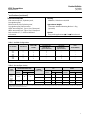
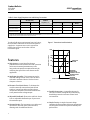
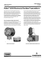
Product Bulletin
4200 Transmitters
62.3:4200
July 2014
D200357X012
Fisherr 4200 Electronic Position Transmitters
The instrument can sense the position of rotary or
sliding‐stem valves, vents, dampers or other devices.
When the instrument is mounted, a potentiometer
shaft is mechanically connected to the device to sense
mechanical motion. For a standard instrument, a
single potentiometer is provided for position input or
an optional dual element potentiometer is available to
allow independent electrical operation of the
transmitter and alarm circuits.
The instrument has standard, or long‐stroke (see
figure 3), capabilities for sliding‐stem actuator
applications. For long‐stroke applications, a multi‐turn
potentiometer attached to a travel transducer
assembly is used to sense linear motion of the actuator
stem or other devices. The instrument with standard
capabilities can also be used on quarter‐turn actuators.
W9274
For instruments equipped with electronic travel limit
alarms, individual electronic high and low alarm
circuits drive separate high and low alarm SPDT relays.
The user adjusts the trip point and deadband of the
high and low alarms to the desired travel limits. When
the sense potentiometer voltage is higher than the
high trip point, the electronic high alarm circuit
de‐energizes the high alarm relay. When the sense
potentiometer voltage is lower than the low trip point,
the low alarm circuit de‐energizes the low alarm relay.
The low trip point may be offset from the high trip
point by as little as 5% of the remaining span. In the
event of a power loss to the alarm circuits, both alarms
are tripped (both relays are de‐energized). This
indicates a system failure because the actuator cannot
be physically at both travel limits simultaneously. The
relay contacts are isolated from the transmitter and
alarm circuits.
W4271-1
FISHER 4200 TRANSMITTER
www.Fisher.com
FISHER 4200 TRANSMITTER ON A CONTROL VALVE
Product Bulletin
4200 Transmitters
62.3:4200
July 2014
D200357X012
Specifications
Operating Influences
Available Configurations
Ambient Temperature: For a 56_C (100_F) change in
normal operating conditions, maximum zero shift is
±0.5%, and the maximum span shift is ±0.75% of span
Power Supply: Output signal changes less than ±0.1%
when operating terminal voltage varies between 11
and 30 volts DC
See table 1
Input Signal Source
J Standard single potentiometer, or optional J dual
potentiometer is the source for the transmitter and
travel limit alarm circuit inputs. Refer to table 2 for
zero and span limits.
Electromagnetic Compatibility for 4211 and 4221
Meets EN 61326‐1 (First Edition)
Immunity—Industrial locations per Table 2 of
the EN 61326‐1 standard. Performance is
shown in table 4 below.
Emissions—Class A
ISM equipment rating: Group 1, Class A
Transmitter Output Signal
Range: 4‐20 mA DC transmitter output
Load Impedance: See figure 1.
Output Current Limit: 30 mA DC maximum
Travel Limit Alarm Relays
Travel Limit Alarms
Type: Two single‐pole, double‐throw relays
Contacts: 1 Form C, silver‐nickel alloy with gold
overlay
Service Rating: The relay rating is 5 amperes at either
30 volts DC or 120 volts AC (resistive load).
Life Expectancy: 100,000 operations at rated load, or
50,000 operations at a typical in‐rush current of 10
amperes with a 120 volt AC lamp or motor load
Number of Possible Alarms: Two or none. Each SPDT
relay indicates limit and fault conditions as follows:
Operating
Condition
Relay Coil
State
NC Contact
State
NO Contact
State
Travel within
limits
energized
open
closed
Travel beyond
limits
de‐energized
closed
open
Power loss
de‐energized
closed
open
Operating Conditions
NC—Normally closed. Contacts are closed when relay is de‐energized
NO—Normally open. Contacts are open when relay is de‐energized.
Power Supply Requirements
See table 3
Recommended Power Supply
Condition
Normal and
Operative Limits
Ambient
Temperature
-40 to 71_C
(-40 to 160_F)
Transportation
and Storage
Limits
-50 to 80_C
(-60 to 180_F)
Ambient
Relative
Humidity
10 to 95%
10 to 95%
Normal
Reference
25_C
(77_F)
40%
Construction Materials
+24 volts DC nominal
Transmitter Housing and Covers: Aluminum Alloy
O‐Rings: Nitrile
Mounting Hardware: Steel
Pipe Plug: Nickel coated steel
Cable: Nylon‐coated stainless steel (long stroke only)
Reference Accuracy
±1% of output span. Includes combined effects of
hysteresis, linearity, and deadband
Mounting
The instrument can mount on the actuator of
sliding‐stem or rotary valves (refer to figure 3), or it
can be used for other applications
Repeatability
±0.25% of span
(continued)
2
Product Bulletin
4200 Transmitters
62.3:4200
July 2014
D200357X012
Specifications (continued)
Electrical Classification
CSA—Intrinsically Safe, Explosion-proof,
Dust‐Ignition proof
FM—Intrinsically Safe, Explosion-proof,
Dust‐Ignition proof, Non‐Incendive
ATEX—Intrinsically Safe, Type n, Dust, Flameproof
IECEx—Intrinsically Safe, Type n, Dust, Flameproof
Refer to tables 5, 6, 7, and 8 for additional
information.
Housing
NEMA 4X; CSA Enclosure 4X; IP66
Approximate Weight
Transmitter Without Mounting Bracket: 1.8 kg
(4 pounds)
Options
Long‐stroke applications: J 12 or J 24 inch travel
NOTE: Specialized instrument terms are defined in ANSI/ISA Standard 51.1 - Process Instrument Terminology.
Table 1. Available Configurations
TRAVEL
TYPE NUMBER
TRANSMITTER
TRAVEL LIMIT
ALARMS
Standard Stroke
Up to 105 mm(1)
(Up to 4.125 Inches)
Long Stroke
Up to 610 mm(1)
(Up to 24 Inches)
DUAL
POTENTIOMETER
4210
4211
4212
4215
X
X
--X
X
--X
X
X
X
X
X
---------
------X
4220
4221
4222
X
X
---
X
--X
-------
X
X
X
-------
1. See table 2 for zero and span limits.
Table 2. Zero and Span Limits(1)
TYPE
NUMBER
DEGREES OF
POTENTIOMETER ROTATION
Span
Zero
Position
Min.
Max.
4210
4211
4212
4215
0 to 90
4220
4221
4222
0 to 884
15
150
mm
LINKAGE
CONNECTION(2)
INCHES
Span
Span
Zero
Position
Min.
Max.
Zero
Position
Min.
Max.
1
0 to 51
8
51
0 to 2
0.315
2
2
0 to 105
17
105
0 to 4.125
0.670
4.125
12‐inch Transducer
0 to 305
105
305
0 to 12
4.125
12
24‐inch Transducer
0 to 610
305
610
0 to 24
12
24
90
884
1. Zero position is the range of values over which the transmitter zero can be adjusted. Span is the range of shaft rotation or stem travel the transmitter span can be adjusted. For example, a
zero position of 45 degrees and a span of 15 degrees means the transmitter output is 4 mA DC after 45 degrees of shaft rotation. The output then increases from 4 mA DC to 20 mA DC as the
shaft rotates from 45 to 60 degrees.
2. Refer to figure 4 for location of connections.
3
Product Bulletin
4200 Transmitters
62.3:4200
July 2014
D200357X012
Table 3. Power Supply Requirements and Wiring Connections
TRANSMITTER TERMINAL
VOLTAGE (VDC)
FIELD WIRING CONNECTIONS
CURRENT
REQUIRED (mA)
Supply Wire(1)
Signal Wire(2)
Relay Return
Wire(3)
20 max.
X
X
---
30
80 max.
X
X
X
30
50 max.
X
---
X
Min
Max
Transmitter Only
11
30
Transmitter with
Travel Limit Alarms
20
Travel Limit Alarms
without Transmitter
20
X indicates this connection required.
1. Supply wire provides power supply positive connection for electronic circuits and relay coils (in instruments with travel limit alarms).
2. Signal wire provides connection for device receiving 4 to 20 mA transmitter signal.
3. Relay return wire provides separate return wire for relay coil currents.
Features
n High Accuracy—A precision film‐element
potentiometer in the standard unit and a precision
multi‐turn wirewound potentiometer in the
long‐stroke unit provide exceptional linearity by
matching the span of the sense element to the
application.
Figure 1. Transmitter Load Limitations
1000
LOAD IMPEDANCE (OHMS)
To reduce field wiring requirements from 4 to 3 wires,
the transmitter and alarm circuits share the positive
supply wire. A separate return wire is required to
isolate relay coil currents from the 4‐20 mA
transmitter signal.
750
650
OPERATING
REGION
500
250
00
10
11
20
24
n Application Versatility—This instrument may be
used with sliding‐stem or rotary valves as well as
with other mechanical devices such as furnace
dampers or louvers.
POWER SUPPLY VOLTAGE (VOLTS DC)
A6765
MAXIMUM
30 TRANSMITTER
TERMINAL VOLTAGE
NOMINAL SUPPLY
VOLTAGE
MINIMUM
TRANSMITTER
TERMINAL VOLTAGE
n Electronic Travel Limit Alarms—To eliminate the
need for externally mounted mechanical limit
switches, instruments with travel limit alarms
incorporate comparator circuits that monitor the
sense potentiometer voltage output.
n Adjustable Deadband—Electronic travel limit alarms
n Durable Construction—A rugged housing and a
corrosion‐resistant coating on the printed wiring
board help protect the instrument from harsh
environments.
have an adjustable deadband up to 10 percent of
the maximum span.
n Simple Circuitry—A simple electronic design
n Compact Design—The instrument, even with travel
limit alarms, uses little space when mounted,
allowing room for additional devices.
4
combines the best qualities of discrete components
and integrated circuits for improved reliability and
performance.
Product Bulletin
4200 Transmitters
62.3:4200
July 2014
D200357X012
Figure 2. Fisher 4210 Transmitter Details
PRINTED
WIRING
BOARD
FIELD PRINTED
WIRING BOARD
RELAY
NUMBER 1
TERMINAL
BLOCK
NUMBER 3
TERMINAL
BLOCK
NUMBER 1
TERMINAL
BLOCK
NUMBER 1
TERMINAL
BLOCK
NUMBER 2
RELAY
NUMBER 2
W9275
W4675‐1
TRANSMITTER COMPARTMENT
n Easy Maintenance—The simple design of the
transmitter and alarms allows easy maintenance.
The high reliability of the instrument requires
minimum spare parts inventory.
n Moisture Resistant—The field wiring compartment is
isolated from the electronic compartment. This
protects the electronic circuits from any moisture
brought into the housing via the field wiring ports.
n Field Reversible Action—The output is easily
reversed in the field simply by switching two
potentiometer leads on the printed wiring board.
FIELD WIRING COMPARTMENT
Applications
Standard Position Transmitter
Sliding‐Stem Valve—In typical valve applications, the
transmitter is mounted on the actuator. Two linkage
configurations sense up to 51 mm (2 inches) or up to
105 mm (4.125 inches) of stem travel. The linkages
incorporate mechanical gearing to linearize the
transformation from linear motion to rotational. To
reduce the possibility of physical damage if the linkage
should slip, the potentiometer has no physical stops.
Zero and span can be adjusted as follows:
n Zero—Between 0 and 51 mm (2 inches) of travel, or
between 0 and 105 mm (4.125 inches) of travel.
n Electromagnetic Interference (EMI) Filters—Filters
between the electronic compartment and the field
wiring compartment of the housing help provide
protection against electromagnetic interference.
n Span—Between 9 mm (0.3 inch) minimum span and
51 mm (2 inches) maximum span, or between
17 mm (0.6 inch) minimum span and 105 mm
(4.125 inches) maximum span.
5
Product Bulletin
4200 Transmitters
62.3:4200
July 2014
D200357X012
Figure 3. Dimensions
PORT
1/2 NPT
(2 PLACES)
TRANSMITTER
COMPARTMENT
102
(4.00)
FIELD WIRING
COMPARTMENT
159
(6.25)
102
(4.00)
CAP
(2 PLACES)
6 (0.25)
DIA.
35
(1.38)
67
(2.62)
21
(0.81)
75
(3.00)
67
(2.62)
END VIEW
POTENTIOMETER
SHAFT
ALLOW 254 mm (10 INCHES)
FOR MAINTENANCE (2 PLACES)
SIDE VIEW
51
(2.00)
5/16‐18UNC
13 DEEP
(0.53)
51
(2.00)
19A7968-E
B1910-3*A
BOTTOM VIEW
Rotary‐Shaft Valve—In typical valve applications, the
transmitter is mounted on the actuator. A coupling
connects the hub of the actuator to the potentiometer
shaft. To reduce the possibility of physical damage if
the coupling should slip, the potentiometer has no
physical stops. Zero and span can be adjusted as
follows:
n Zero—Between 0 and 90 degrees of shaft rotation.
n Span—Between 15 and 90 degrees of shaft rotation.
6
mm
(INCH)
Other Devices—The transmitter is mounted such that
the potentiometer shaft or linkage aligns with the
motion of the device. The motion of the device should
not exceed the zero and span input signal limits in
degrees of rotation.
Product Bulletin
4200 Transmitters
62.3:4200
July 2014
D200357X012
Long‐Stroke Position Transmitter
Long‐Stroke Sliding‐Stem Valve—The transmitter is
mounted on the actuator as shown in figure 3. The
travel transducer assembly can sense from a 105 mm
(4.125 inch) minimum to a 610 mm (24 inch)
maximum stem travel. The sensing element is a
multi‐turn potentiometer with physical stops. Two
travel transducer sizes are available for long stroke
applications.
limit alarms, and the instrument with alarms only (no
transmitter circuits), use terminal blocks numbered 1,
2, and 3 (see figure 2) on the printed wiring board.
These terminal blocks are accessible when the field
wiring compartment cover is removed. The instrument
with transmitter circuits only (no alarms) uses a barrier
strip mounted in the field wiring compartment
without the printed wiring board. Dimensions of the
transmitter housing are shown in figure 3. Mounting
dimensions are shown in figure 4.
n Zero—Between 0 and 305 mm (12 inches) for the
small transducer. Between 0 and 610 mm (24
inches) for the large transducer.
n Span—Between 105 mm (4.125 inches) minimum
and 305 mm (12 inches) maximum for the small
transducer. Between 305 mm (12 inches) minimum
and 610 mm (24 inches) maximum for the large
transducer.
Other Devices—The transmitter is mounted such that
the travel transducer aligns with the motion of the
device to allow straight retraction of the cable to the
transducer. The motion of the device should not
exceed the zero and span limits in mm (inches).
Ordering Information
When ordering, specify:
1. Transmitter type number.
2. Actuator type, size, and length of stroke.
(Note: For Fisher 585CLS actuators, specify yoke
boss and cylinder size.)
3. Valve body design.
4. Other applications
Installation
Field wiring is inserted into one of the ports and
connected to the terminal blocks mounted on the
printed wiring board in the field wiring compartment.
The instrument with transmitter circuits and travel
Note
Contact your Emerson Process Management sales office for
assistance in determining the type and style of linkage and
mounting hardware required for the application.
7
Product Bulletin
4200 Transmitters
62.3:4200
July 2014
D200357X012
Figure 4. Mounting Dimensions
48
(1.88)
108
(4.25)
86
(3.40)
271
(10.69)
ACTUATOR
HOUSING
204
(8.00)
51
(2.00)
CONNECTION
NUMBER 2
CONNECTION
NUMBER 1
TYPICAL MOUNTING BRACKET DIMENSIONS
FOR SLIDING‐STEM ACTUATORS
TYPICAL MOUNTING BRACKET DIMENSIONS
FOR ROTARY‐SHAFT ACTUATORS
FISHER 4200 TRANSMITTER MOUNTING
10
(0.38)
204
(8)
1
111
(4.38)
GE16563‐A
MOUNTING BRACKET DIMENSIONS FOR
FISHER 585CLS ACTUATORS
WITH A 152 mm (6‐INCH) CHANNEL
Note:
1 For other sizes of 585CLS actuators, the mounting plate length
will change depending on the channel width.
8
Product Bulletin
4200 Transmitters
62.3:4200
July 2014
D200357X012
Table 4. Fisher 4211 and 4221 Electronic Position Transmitter EMC Summary Results—Immunity
Port
Enclosure
Phenomenon
Basic Standard
Performance
Criteria(1)
Electrostatic Discharge (ESD)
IEC 61000‐4‐2
4 kV contact
8 kV air
A
Radiated EM field
IEC 61000‐4‐3
80 to 1000 MHz @ 10V/m with 1 kHz AM at 80%
1400 to 2000 MHz @ 3V/m with 1 kHz AM at 80%
2000 to 2700 MHz @ 1V/m with 1 kHz AM at 80%
A
IEC 61000‐4‐8
60 A/m at 50 Hz
A
IEC 61000‐4‐4
1 kV
A
IEC 61000‐4‐5
1 kV (line to ground only, each)
B
IEC 61000‐4‐6
150 kHz to 80 MHz at 3 Vrms
1 kHz AM at 80%
A
Rated power frequency magnetic
field
Burst (fast transients)
I/O signal/control
Test Level
Surge
Conducted RF
Specification limit = ±1% of span
1. A = No degradation during testing. B = Temporary degradation during testing, but is self‐recovering.
Table 5. Hazardous Area Classifications—CSA (Canada)
Certification
Body
CSA
Type
Certification Obtained
Entity Rating
Temperature Code
Enclosure Rating
Ui = 30 VDC
Ii = 150 mA
Pi = 1.0 W
Ci = 5 nF
Li = 0 mH
T4 (Tamb ≤ 71°C)
4X
4211, 4221
Intrinsically Safe
Class I,II,III Division 1 GP A,B,C,D,E,F,G
per drawing GE16020
4210, 4211,
4212, 4215,
4220, 4221,
4222
Explosion-proof
Ex d IIC T5
Class I, Division 1 GP B,C,D T5
---
T5 (Tamb ≤ 71°C)
4X
4210, 4211,
4212, 4215,
4220, 4221,
4222
Class II Division 1 GP E,F,G T5
---
T5 (Tamb ≤ 71°C)
4X
Table 6. Hazardous Area Classifications—FM (United States)
Certification
Body
FM
Type
Certification Obtained
4211, 4221
Intrinsically Safe
Class I,II,III Division 1 GP A,B,C,D,E,F,G
per drawing GE16019
4210, 4211,
4212, 4215,
4220, 4221,
4222
Explosion-proof
Class I Zone 1 AEx d IIC T5
Class I, Division 1 GP A,B,C,D T5
4211, 4221
4210, 4211,
4212, 4215,
4220, 4221,
4222
Entity Rating
Vmax = 30 VDC
Imax = 150 mA
Pi =1.0 W
Ci = 18 nF
Li = 0 mH
Temperature Code
Enclosure Rating
T4 (Tamb ≤ 71°C)
4X
---
T5 (Tamb ≤ 71°C)
4X
Class I Division 2 GP A,B,C,D T4
Class II Division 2 GP F,G T4
---
T4 (Tamb ≤ 71°C)
4X
Class II Division 1 GP E,F,G T5
---
T5 (Tamb ≤ 71°C)
4X
9
Product Bulletin
4200 Transmitters
62.3:4200
July 2014
D200357X012
Table 7. Hazardous Area Classifications—ATEX
Certificate
Type
Certification Obtained
Entity Rating
Temperature Code
Enclosure Rating
II 1 GD
4211, 4221
Intrinsically Safe
Gas
Ex ia IIC T4/T5 Ga
Dust
Ex ta IIIC T81°C Da (Tamb ≤ 71°C)
Ex ta IIIC T50°C Da (Tamb ≤ 40°C)
Ui = 30 VDC
Ii = 150 mA
Pi = 1.0 W
Ci = 5 nF
Li = 0 mH
T4 (Tamb ≤ 71°C)
T5 (Tamb ≤ 40°C)
IP66
---
II 3 GD
Type n
Gas
Ex nA IIC T4 Gc
Dust
Ex tc IIIC T81°C Dc (Tamb ≤ 71°C)
II 2 GD
ATEX
4210, 4211,
4212, 4215,
4220, 4221,
4222
Flameproof
Gas
Ex d IIC T5/T6 Gb IP66
Dust
Ex tb IIIC T72°C Db (Tamb -20°C to 56°C)
T4 (Tamb ≤ 71°C)
---
IP66
---
---
T5 (Tamb ≤ 71°C)
T6 (Tamb ≤ 56°C)
IP66
---
Table 8. Hazardous Area Classifications—IECEx
Certificate
Type
4211, 4221
IECEx
4210, 4211,
4212, 4215,
4220, 4221,
4222
10
Certification Obtained
Intrinsically Safe
Gas
Ex ia IIC T4/T5 Ga
Dust
Ex ta IIIC T81°C Da (Tamb ≤ 71°C)
Ex ta IIIC T50°C Da (Tamb ≤ 40°C)
Type n
Gas
Ex nA IIC T4 Gc
Dust
Ex tc IIIC T81°C Dc (Tamb ≤ 71°C)
Flameproof
Gas
Ex d IIC T5/T6 Gb IP66
Dust
Ex tb IIIC T72°C Db (Tamb -20°C to 56°C)
Entity Rating
Ui = 30 VDC
Ii = 150 mA
Pi = 1.0 W
Ci = 5 nF
Li = 0 mH
Temperature Code
Enclosure Rating
T4 (Tamb ≤ 71°C)
T5 (Tamb ≤ 40°C)
IP66
---
T4 (Tamb ≤ 71°C)
---
IP66
---
---
T5 (Tamb ≤ 71°C)
T6 (Tamb ≤ 56°C)
---
IP66
4200 Transmitters
D200357X012
Product Bulletin
62.3:4200
July 2014
11
Product Bulletin
62.3:4200
July 2014
4200 Transmitters
D200357X012
Neither Emerson, Emerson Process Management, nor any of their affiliated entities assumes responsibility for the selection, use or maintenance
of any product. Responsibility for proper selection, use, and maintenance of any product remains solely with the purchaser and end user.
Fisher is a mark owned by one of the companies in the Emerson Process Management business unit of Emerson Electric Co. Emerson Process Management,
Emerson, and the Emerson logo are trademarks and service marks of Emerson Electric Co. All other marks are the property of their respective owners.
The contents of this publication are presented for informational purposes only, and while every effort has been made to ensure their accuracy, they are not
to be construed as warranties or guarantees, express or implied, regarding the products or services described herein or their use or applicability. All sales are
governed by our terms and conditions, which are available upon request. We reserve the right to modify or improve the designs or specifications of such
products at any time without notice.
Emerson Process Management
Marshalltown, Iowa 50158 USA
Sorocaba, 18087 Brazil
Chatham, Kent ME4 4QZ UK
Dubai, United Arab Emirates
Singapore 128461 Singapore
www.Fisher.com
E
121985, 2014 Fisher Controls International LLC. All rights reserved.