1
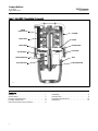
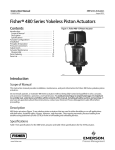
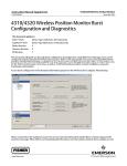
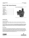
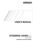
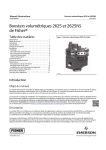
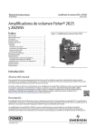
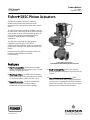
Product Bulletin 585C Actuator 61.2:585C September 2014 D102086X012 Fisherr 585C Piston Actuators The 585C linear piston actuator is a powerful, double-acting actuator that provides accurate throttling or on-off operation for sliding-stem control valves. The 585C piston actuator family is available in sizes 25 to 130 to cover a wide range of thrust and travel length requirements. It can be used with switching valves for on-off control, or with the DVC6200 digital valve controller or 3600 positioner for throttling applications. The 585C has a wide-range of supply pressure capabilities, up to 150 psig. As the 585C is double-acting, the positioner supplies air to both sides of the piston, resulting in stiff, precise movement and control. Information for the 585CLS long stroke actuator can be found in Fisher bulletin 61.2:585CLS (D103792X012). X0175-1 Fisher 585C Piston Actuator with FIELDVUE™ DVC6200 Digital Valve Controller Features High Thrust Capability-- With standard air supply, the Size 130 Fisher 585C can produce up to 111,000 Newtons (25,000 lbs) of force. Wide Range of Sizes-- The 585C family of actuators offers a wide range of sizes, with piston areas of 168 sq cm (26 sq in) up to 1,429 sq cm (221.5 sq in). Rugged Construction-- The 585C standard yoke material is ductile iron, resulting in robust construction and increased thrust capability. www.Fisher.com Broad Travel Capability-- 585C piston actuators provide standard travel lengths of up to 203 mm (8 inches). High-Performance Instrumentation-- 585C actuators are available with a variety of positioners and accessories, including the FIELDVUE DVC6200 digital valve controller. The 377 trip valve and tank system are also available for fail-safe action. Product Bulletin 585C Actuator 61.2:585C September 2014 D102086X012 Figure 1. Fisher 585C Piston Actuator Components SPRING (SIZES 25 & 50) CYLINDER TRAVEL STOP PISTON STEM O-RING PISTON O-RING CAP SCREW SEAL BUSHING TRAVEL INDICATOR YOKE ACTUATOR STEM STEM CONNECTOR W7447-1 Contents Features . . . . . . . . . . . . . . . . . . . . . . . . . . . . . . . . . . . . . Specifications . . . . . . . . . . . . . . . . . . . . . . . . . . . . . . . . Features and Advantages . . . . . . . . . . . . . . . . . . . . . . . Principle of Operation . . . . . . . . . . . . . . . . . . . . . . . . . Instrument and Accessory Selection . . . . . . . . . . . . . 2 1 3 4 4 6 Installation . . . . . . . . . . . . . . . . . . . . . . . . . . . . . . . . . . 6 Actuator Data . . . . . . . . . . . . . . . . . . . . . . . . . . . . . . . . 6 Handwheel Specifications . . . . . . . . . . . . . . . . . . . . . 12 Dimensions . . . . . . . . . . . . . . . . . . . . . . . . . . . . . . . . . 13 Product Bulletin 585C Actuator 61.2:585C September 2014 D102086X012 Specifications Operating Pressure(1) Sizes 25-50: Maximum Allowable: 10.3 bar (150 psig) Minimum Recommended: 1.4 bar (20 psig) Sizes 60-130: Maximum Allowable: See table 8. Minimum Recommended: 2.4 bar (35 psig) Travel See table 2 Construction Materials Stroking Speeds Varies with actuator size, actuator spring, travel, and supply pressure. If stroking speed is critical, consult your Emerson Process Management sales office Piston Area See table 8 Cylinder Volumetric Displacement See table 2 Operative Temperature Limits(1) For All Sizes: With Nitrile O-Rings: -40 to 80_C (-40 to 175_F), standard With Fluorocarbon O-Rings: -18 to 149_C (0 to 300_F), optional Yoke Boss and Valve Stem Diameters See table 3 Pressure Connections Sizes 25 and 60: J 1/4 NPT internal (standard), or J 3/8 NPT internal (optional) Size 50: J 1/4 NPT internal (standard), or J 1/2 NPT internal (optional) Sizes 68-130: J 1/2 NPT internal (standard) Dimensions See figures 6 and 7 Material Ductile Iron Piston Aluminum Cylinder Aluminum Bolting and Fasteners NCF (non-corroding finish) Springs (sizes 25 & 50 only) Alloy Steel O-Rings Nitrile (std), Fluorocarbon, or EPDM Actuator Stem Chrome-plated Steel Stem Connection Stainless Steel Travel Indicator Scale Stainless Steel Paint Polyester Powder Actuator Stem (sizes 60-130 only) S41600 (416) SST, Chrome Plate Cylinder Seal Bushings (sizes 60-130 only) Brass Thrust Capabilities See tables 4, 5, 6, 7, and 8 Part Yoke Instrument Mounting Universal NAMUR mounting Approximate Weights (less positioner and handwheel) Size 25: 2-1/8 inch yoke boss, 7 kg (16 pounds) 2-13/16 inch yoke boss, 8 kg (17 pounds) Size 50: 2-13/16 inch yoke boss, 20 kg (45 pounds) 3-9/16 inch yoke boss, 22 kg (48 pounds) Size 60: 31 kg (68 pounds) Size 68: 54 kg (120 pounds) Size 80: 102 kg (225 pounds) Size 100: 113 kg (250 pounds) Size 130: 188 kg (415 pounds) Options Sizes 25 and 50: J Top-mounted handwheel, see figures 6 and 7 and table 9 J Cylinder bypass valve J Limit switches J Fisher 4200 position transmitter Sizes 60-130: J Integral side-mounted handwheel Sizes 25-130: J FIELDVUE mounting options J Fisher 377 trip valve system to fail actuator J Up or J down or J lock in last position J TopWorx DXP M21GNEB electrical valve stem position switch J Micro-Switch limit switches 1. The pressure/temperature limits in this bulletin and any applicable standard or code limitation for valve should not be exceeded. 3 Product Bulletin 585C Actuator 61.2:585C September 2014 D102086X012 Features and Advantages Table 1. Features and Advantages Features Advantages High thrust capability With air supply capability of up to 150 psig, the 585C can produce up to 111,000 Newtons (25,000 pounds) thrust to overcome high valve unbalance. Stroke Length Capability Depending on size, strokes of up to 203 mm (8 inches) are available. Wide range of sizes The 585C is available in standard sizes 25, 50, 60, 68, 80, 100, and 130. Valve mounting capability Depending on size, the 585C can be mounted to yoke boss diameters of 2-1/8 inches through 5-inches, and valve stem diameters of up to 1-1/4 inch. Positioner mounting capability Universal NAMUR mounting provides a consistent mounting method for all sizes. This mounting capability provides vibration resistance per ISA-S75.13. High frequency response The double acting construction allows quick response to instrument signals. Stiff construction Pressure on both sides of the piston, plus the relatively small volume of air within the cylinder, results in stiff, precise positioning. Handwheels 585C size 25 and 50 actuators are available with a top-mounted handwheel. All other 585C actuator sizes can accommodate a side-mounted handwheel. Bias springs The sizes 25 and 50 are available with bias springs. A bias spring under the piston fully retracts the actuator stem upon loss of supply air, while a bias spring on top of the piston fully extends the actuator stem. The spring bias mode is easily reversed without the need for additional parts. Figure 2. Fisher 585C Piston Actuator Without Springs Principle of Operation The 585C piston actuator (figures 1 and 2) uses a piston that moves inside the actuator cylinder. An O-ring (see figure 1) provides a seal between the piston and the cylinder. From an equilibrium state, the actuator reacts to a force unbalance that is created by increasing supply pressure on one side of the piston,and decreasing it on the other. This moves the piston up or down, and results in a repositioning of the valve control element. E0409 4 Product Bulletin 585C Actuator 61.2:585C September 2014 D102086X012 Figure 3. Fisher 585C Piston Actuator with Handwheel E0410 Figure 4. Fisher 585C Piston Actuator with Spring Return W7447-1 Actuator with Handwheel (figures 3 and 6) The handwheel version can be used to open or close the valve manually (either during normal operation or in an emergency), to position the valve at any point in the stroke, or to act as a travel stop. Size 25 and 50 actuators use an integral top-mounted handwheel. See figure 6. Size 60 to 130 actuators use a side-mounted handwheel, and come with a spring-loaded ball detent which prevents vibration from changing the handwheel setting. Handwheels for most types are either 203 mm (8 inches) in diameter with beveled gears or 432 mm (17 inches) in diameter with worm gears. Actuator with Spring Return (figure 4) 585C size 25 & 50 actuators are available with bias springs. The 585C actuator with bias spring has the spring under the piston and fully retracts the actuator stem upon loss of cylinder pressure. The bias spring in the 585CR actuator is on top of the piston and fully extends the actuator stem upon loss of cylinder pressure. No additional parts are required to convert from one actuator type to the other. 5 Product Bulletin 585C Actuator 61.2:585C September 2014 D102086X012 Instrument and Accessory Selection normal installation is with the actuator vertical above the valve. Actuator and positioner dimensions are shown in figures 6, 7, and 8. An excellent selection of sensitive and accurate instruments and accessories is available for 585C piston actuators. These include FIELDVUE DVC6200 digital valve controllers, 3600 pneumatic (P/P) and electro-pneumatic (I/P) positioners, TopWorx™ DXP M21GNEB electrical valve stem position switch, 377 trip valve, 4200 electronic position transmitter, and limit switches. They are described in separate publications. Contact your Emerson Process Management sales office for details. If the supply source is capable of exceeding the maximum actuator operating pressure or instrument supply pressure, appropriate steps must be taken during installation to protect the instrument and all connected equipment against overpressure. Actuator Data Installation See table 2 for piston cylinder clearance volumes, table 3 for yoke boss and valve stem diameters, and tables 4, 5, 6, 7, and 8 for actuator thrust capabilities. The actuator may be installed in any orientation but Table 2. Fisher 585C Piston Cylinder Clearance Volumes PISTON AT TOP OF CYLINDER (SPRINGS BELOW PISTON FOR SIZE 25 AND 50) Actuator Size Piston Area Maximum Actuator Travel Upper Clearance Volume (figure 5) cm3 Inches3 Volume Below Piston (figure 5) cm3 Inches3 cm2 Inches2 mm Inches 25 168 26 29 1.125 104 6.3 1750 107 50 303 47 51 2 330 20 5200 320 51 2 310 19 2700 163 100 4 310 19 4400 270 200 8 310 19 8200 500 51 2 1230 75 7500 460 102 4 1230 75 7500 460 203 8 1230 75 13300 810 102 4 1230 75 7500 460 203 8 1230 75 13300 810 102 4 1700 104 10700 650 203 8 1700 104 19200 1170 102 4 4600 280 18500 1130 203 8 4600 280 33000 2000 60 68 80 358 55.5 571 88.5 571 88.5 100 842 130.5 130 1430 221.5 PISTON AT BOTTOM OF CYLINDER (SPRINGS ABOVE PISTON FOR SIZE 25 AND 50) Actuator Size 6 Piston Area Maximum Actuator Travel Lower Clearance Volume (figure 5) cm3 Inches3 Volume Above Piston (figure 5) cm3 Inches3 cm2 Inches2 mm Inches 25 168 26 29 1.125 77 4.7 1790 109 50 303 47 51 2 350 22 5200 320 Product Bulletin 585C Actuator 61.2:585C September 2014 D102086X012 Table 3. Yoke Boss and Valve Stem Diameters ACTUATOR SIZE YOKE BOSS DIAMETER VALVE STEM DIAMETER mm Inches mm Inches 25 54 71 2-1/8 2-13/16 9.5 12.7 3/8 1/2 50 71 90 2-13/16 3-9/16 12.7 19.1 1/2 3/4 60 90 3-9/16 19.1 3/4 68 90 3-9/16 19.1 3/4 1 1-1/4 80 127 5, 5H 25.4 31.8 100 127 5, 5H 25.4 31.8 1 1-1/4 130 127 5, 5H 25.4 31.8 1 1-1/4 1. Heavy actuator to bonnet bolting. Figure 5. Clearance Volumes UPPER CLEARANCE VOLUME VOLUME ABOVE PISTON VOLUME BELOW PISTON LOWER CLEARANCE VOLUME 44B7218-C 44B7217-C 7 Product Bulletin 585C Actuator 61.2:585C September 2014 D102086X012 Actuator Thrust Capabilities Table 4. Fisher 585C Size 25 and 50 Actuator Thrust Capabilities, U.S. Units (spring retracts stem) ACTUATOR SIZE 25 50 ACTUATOR SPRING THRUST, POUNDS SPRING STEM RATE, TRAVEL, Stem Stem lb/in INCHES Retracted Extended NET THRUST FOR 585C WITH ACTUATOR STEM FULLY EXTENDED AT FULL TRAVEL Operating Pressure, psig(1) 40 50 60 70 80 100 110 125 150 Force, Pounds 0 All 0 0 1040 1300 1560 1820 2080 2340 2600 2860 3250 3900 Springs Not Used 200 0.5625 0.75 0.875 1.125 200 200 200 200 313 350 375 425 730 690 660 610 990 950 920 870 1250 1210 1180 1130 1510 1470 1440 1390 1760 1730 1700 1650 2020 1990 1960 1910 2280 2250 2220 2170 2540 2510 2480 2430 2930 2900 2870 2820 3580 3550 3520 3470 Gold 400 0.5625 0.75 0.875 1.125 400 400 400 400 625 700 750 850 410 340 290 190 670 600 550 450 930 860 810 710 1190 1120 1070 970 1450 1380 1330 1230 1710 1640 1590 1490 1970 1900 1850 1750 2230 2160 2110 2010 2620 2550 2500 2400 3270 3200 3150 3050 Light Green 500 0.5625 0.75 0.875 1.125 500 500 500 500 781 875 938 1063 260 160 100 X 520 420 360 240 780 680 620 500 1040 940 880 760 1300 1200 1140 1010 1560 1460 1400 1270 1820 1720 1660 1530 2080 1980 1920 1790 2460 2370 2310 2180 3110 3020 2960 2830 White 700 0.5625 0.75 0.875 1.125 700 700 700 700 1094 1225 1313 1488 X X X X 200 70 X X 460 330 250 70 720 590 510 330 980 850 760 590 1240 1110 1020 850 1500 1370 1280 1110 1760 1630 1540 1370 2150 2020 1930 1760 2800 2670 2580 2410 Gold & White 900 0.5625 0.75 0.875 1.125 900 900 900 900 1406 1575 1688 1913 X X X X X X X X 150 X X X 410 240 130 X 670 500 390 160 930 760 650 420 1190 1020 910 680 1450 1280 1170 940 1840 1670 1560 1330 2490 2320 2210 1980 Light Green & White 0 All 0 0 1840 2300 2760 3220 3680 4140 4600 5060 5750 6900 Springs Not Used 330 0.75 0.875 1.125 1.5 2 330 330 330 330 330 578 619 701 825 990 1310 1270 1180 1060 900 1780 1740 1660 1530 1370 2250 2210 2130 2000 1840 2720 2680 2600 2470 2310 3190 3150 3070 2950 2780 3660 3620 3540 3420 3250 4140 4090 4010 3890 3720 4610 4570 4480 4360 4190 5310 5270 5190 5070 4900 6490 6450 6370 6250 6080 Pink 600 0.75 0.875 1.125 1.5 2 600 600 600 600 600 1050 1125 1275 1500 1800 840 760 610 390 90 1310 1230 1080 860 560 1780 1700 1550 1330 1030 2250 2170 2020 1800 1500 2720 2650 2500 2270 1970 3190 3120 2970 2740 2440 3660 3590 3440 3210 2910 4130 4060 3910 3680 3380 4840 4770 4620 4390 4090 6020 5950 5800 5570 5270 Light Blue 930 0.75 0.875 1.125 1.5 2 930 930 930 930 930 1628 1744 1976 2325 2790 260 140 X X X 730 610 380 30 X 1200 1080 850 500 40 1670 1560 1320 970 510 2140 2030 1790 1450 980 2610 2500 2270 1920 1450 3090 2970 2740 2390 1920 3560 3440 3210 2860 2390 4260 4150 3910 3570 3100 5440 5330 5090 4750 4280 Pink & Light Blue 1550 0.75 0.875 1.125 1.5 2 1550 1550 1550 1550 1550 2710 2906 3294 3875 4650 X X X X X X X X X X 110 X X X X 580 385 X X X 1050 855 465 X X 1520 1325 935 355 X 1990 1795 1405 825 50 2460 2265 1875 1295 520 3165 2970 2580 2000 1225 4345 4150 3760 3180 2405 Green 1880 0.75 0.875 1.125 1.5 2 1880 1880 1880 1880 1880 3290 3525 3995 4700 5640 X X X X X X X X X X X X X X X X X X X X 470 235 X X X 940 705 235 X X 1410 1175 705 X X 1880 1645 1175 470 X 2585 2350 1880 1175 235 3765 3530 3060 2355 1415 Pink & Green X indicates where the listed supply pressure is not sufficient to overcome the opposing bias spring effect. 1. The maximum design pressure for size 25 and 50 actuator is 150 psig. Maximum rating for applications is 125 psig. 8 90 SPRING COLOR Product Bulletin 585C Actuator 61.2:585C September 2014 D102086X012 Table 5. Fisher 585C Size 25 and 50 Actuator Thrust Capabilities, Metric Units (spring retracts stem) ACTUACTU- SPRING ATOR STEM ATOR RATE, SIZE N/mm TRAVEL, mm 25 SPRING THRUST, N NET THRUST FOR 585C WITH ACTUATOR STEM FULLY EXTENDED AT FULL TRAVEL Operating Pressure, bar(1) Stem Retracted Stem Extended 2.8 3.4 4.1 4.8 5.5 6.2 6.9 7.6 SPRING COLOR 8.6 10.3 11,565 12,722 14,457 17,348 Springs Not Used Force, N 0 All 0 0 4626 5783 6939 8096 9252 10,409 35.0 14.3 19.1 22.2 28.6 890 890 890 890 1393 1558 1669 1891 3247 3069 2936 2713 4404 4226 4092 3870 5560 5382 5249 5026 6717 6539 6405 6183 7829 7695 7562 7340 8985 8852 8718 8496 10,142 10,008 9875 9653 11,298 11,165 11,032 10,809 13,033 12,900 12,766 12,544 15,925 15,791 15,658 15,435 Gold 70.1 14.3 19.1 22.2 28.6 1780 1780 1780 1780 2781 3115 3338 3783 1824 1512 1290 845 2980 2669 2447 2002 4137 3825 3603 3158 5293 4982 4760 4315 6450 6139 5916 5471 7606 7295 7073 6628 8763 8452 8229 7784 9919 9608 9386 8941 11,654 11,343 11,121 10,676 14,546 14,234 14,012 13,567 Light Green 87.6 14.3 19.1 22.2 28.6 2225 2225 2225 2225 3475 3894 4174 4730 1156 712 445 X 2313 1868 1601 1068 3470 3025 2758 2224 4626 4181 3914 3381 5783 5338 5071 4493 6939 6494 6227 5649 8096 7651 7384 6806 9252 8807 8541 7962 10,943 10,542 10,275 9697 13,834 13,434 13,167 12,588 White 122.6 14.3 19.1 22.2 28.6 3115 3115 3115 3115 4868 5451 5843 6622 X X X X 890 311 X X 2046 1468 1112 311 3203 2624 2269 1468 4359 3781 3381 2624 5516 4938 4537 3781 6672 6094 5694 4938 7829 7251 6850 6094 9564 8985 8585 7829 12,455 11,877 11,476 10,720 Gold & White 157.7 14.3 19.1 22.2 28.6 4005 4005 4005 4005 6257 7009 7512 8513 X X X X X X X X 667 X X X 1824 1068 578 X 2980 2224 1735 712 4137 3381 2891 1868 5293 4537 4048 3025 6450 5694 5204 4181 8185 7428 6939 5916 11,076 10,320 9831 8807 Light Green & White 0 All 0 0 8180 10,200 12,300 14,300 16,400 18,400 20,500 22,500 25,600 30,700 Springs Not Used 57.8 19.1 22.2 28.6 38.1 50.8 1468 1468 1468 1468 1468 2571 2753 3118 3670 4404 5827 5649 5249 4715 4003 7918 7740 7384 6806 6094 10,008 9831 9475 8896 8185 12,099 11,921 11,565 10,987 10,275 14,190 14,012 13,656 13,122 12,366 16,280 16,102 15,747 15,213 14,457 18,416 18,193 17,837 17,303 16,547 20,506 20,328 19,928 19,394 18,638 23,620 23,442 23,086 22,552 21,796 28,869 28,691 28,335 27,801 27,045 Pink 105.1 19.1 22.2 28.6 38.1 50.8 2669 2669 2669 2669 2669 4671 5004 5671 6672 8007 3736 3381 2713 1735 400 5827 5471 4804 3825 2491 7918 7562 6895 5916 4582 10,008 9653 8985 8007 6672 12,099 11,788 11,121 10,097 8763 14,190 13,878 13,211 12,188 10,854 16,280 15,969 15,302 14,279 12,944 18,371 18,060 17,392 16,369 15,035 21,529 21,218 20,551 19,528 18,193 26,778 26,467 25,800 24,777 23,442 Light Blue 162.9 19.1 22.2 28.6 38.1 50.8 4137 4137 4137 4137 4137 7242 7758 8790 10,342 12,410 1157 623 X X X 3247 2713 1690 133 X 5338 4804 3781 2224 178 7428 6939 5872 4315 2269 9519 9030 7962 6450 4359 11,610 11,121 10,097 8541 6450 13,745 13,211 12,188 10,631 8541 15,836 15,302 14,279 12,722 10,631 18,949 18,460 17,392 15,880 13,789 24,198 23,709 22,641 21,129 19,038 Pink & Light Blue 271.4 19.1 22.2 28.6 38.1 50.8 6894 6894 6894 6894 6894 12054 12925 14652 17236 20683 X X X X X X X X X X 489 X X X X 2580 1712 X X X 4670 3803 2068 X X 6761 5894 4159 1579 X 8852 7984 6249 3670 222 10942 10075 8340 5760 2313 14078 13211 11476 8896 5449 19,328 18,460 16,725 14,145 10,698 Green 329.2 19.1 22.2 28.6 38.1 50.8 8362 8362 8362 8362 8362 14634 15679 17770 20906 25087 X X X X X X X X X X X X X X X X X X X X 2091 1045 X X X 4181 3136 1045 X X 6272 5226 3136 X X 8362 7317 5226 2091 X 11498 10453 8362 5226 1045 16,748 15,702 13,612 10,476 6294 Pink & Green 50 X–Indicates where the listed supply pressure is not sufficient to overcome the opposing bias spring effect. 1. The maximum design pressure for size 25 and 50 actuator is 10.3 bar. Maximum rating for applications is 8.6 bar. 9 Product Bulletin 585C Actuator 61.2:585C September 2014 D102086X012 Table 6. Fisher 585CR Size 25 and 50 Actuator Thrust Capabilities, U.S. Units (spring extends stem) ACTUATOR SIZE 25(2) 50(3) 40 50 60 70 0 SPRING THRUST W/ ACTUATOR STEM EXTENDED, POUNDS 0 1040 1300 1560 1820 2080 200 200 1240 1500 1760 2020 2280 400 400 1440 1700 1960 2220 500 500 1540 1800 2060 700 700 1740 2000 2260 900 900 1940 2200 0 0 1840 2300 330 330 2210 600 600 SPRING RATE, lb/in TOTAL THRUST FOR 585CR WITH ACTUATOR STEM FULLY EXTENDED Operating Pressure, psig(1) 80 90 SPRINGS USED, BY COLOR 100 110 125 150 2340 2600 2860 3250 3900 2540 2800 3060 3450 X Gold 2480 2740 3000 3260 3650 X Light Green 2320 2580 2840 3100 3360 3750 X White 2520 2780 3040 3300 3560 X X Gold & White 2460 2720 2980 3240 3500 3760 X X Light Green & White 2760 3220 3680 4140 4600 5060 5750 6900 Springs Not Used 2680 3150 3620 4090 4560 5030 5500 6205 X Pink 2480 2950 3420 3890 4360 4830 5300 5770 6475 X Light Blue Pink & Light Blue Force, Pounds Springs Not Used 930 930 2810 3280 3750 4220 4690 5160 5630 6100 6805 X 1550 1550 3430 3900 4370 4840 5310 5780 6250 6720 X X Green 1880 1880 3760 4230 4700 5170 5640 6110 6580 7050 X X Pink & Green X indicates where the listed supply pressure is not sufficient to overcome the opposing bias spring effect. 1. The maximum design pressure for size 25 and 50 actuator is 150 psig. 2. Maximum thrust is 3900 lbs. 3. Maximum thrust is 6900 lbs. Table 7. Fisher 585CR Size 25 and 50 Actuator Thrust Capabilities, Metric Units (spring extends stem) ACTUATOR SIZE 25(2) 50(3) 0 SPRING THRUST W/ ACTUATOR STEM EXTENDED, N 0 4626 5782 6939 8095 9251 35.0 890 5516 6672 7828 8985 10141 70.0 1780 6405 7562 8718 9874 SPRING RATE, N/mm TOTAL THRUST FOR 585CR WITH ACTUATOR STEM FULLY EXTENDED Operating Pressure, bar(1) 2.8 3.4 4.1 4.8 5.5 6.2 6.9 7.6 8.6 10.3 10408 11565 12721 14456 17347 11298 12454 13610 15346 X Gold 11031 12188 13344 14500 16235 X Light Green Force, N Springs Not Used 87.6 2225 6850 8006 9163 10319 11476 12632 13789 14945 16680 X White 122.6 3115 7740 8896 10052 11209 12365 13655 14678 15835 X X Gold & White 157.6 4005 8629 9786 10942 12099 13255 14412 15568 16724 X X Light Green & White 0 0 8180 10200 12300 14300 16400 18400 20500 22500 25600 30700 Springs Not Used 57.8 1468 9830 11921 14011 16102 18192 20282 22373 24464 27600 X Pink 105.1 2670 11031 13122 15212 17303 19393 21484 23574 25665 28800 X Light Blue 162.8 4135 12499 14589 16680 18770 20861 22952 25042 27133 30269 X Pink & Light Blue 271.4 6894 15256 17347 19438 21528 23619 25709 27800 29891 X X Green 329.2 8362 16724 18815 20906 22996 25087 27177 29268 31358 X X Pink & Green X indicates where the listed supply pressure is not sufficient to overcome the opposing bias spring effect. 1. The maximum design pressure for size 25 and 50 actuator is 10.3 bar. 2. Maximum thrust is 17347 N. 3. Maximum thrust is 30700 N. 10 SPRINGS USED, BY COLOR Product Bulletin 585C Actuator 61.2:585C September 2014 D102086X012 Table 8. Fisher 585C Thrust (springless construction) ACTUATOR SIZE PISTON AREA TOTAL THRUST FOR 585C(1) Operating Pressure, bar(3) 2.8 3.4 4.1 4.8 cm2 5.5 6.2 6.9 7.6 8.6 10.3 Force, Newtons(2) MAXIMUM ALLOWABLE THRUST Newtons 25 168 4630 5780 6940 8100 9260 10400 11600 12700 14500 17300 17300 50 303 8180 10200 12300 14300 16400 18400 20500 22500 25600 30700 31400 60(3) 358 9880 12300 14800 17300 19800 22200 24700 27200 30900 36900 36900 68(3) 571 15700 19700 23600 27600 31500 35400 39400 43300 49200 55600 55600(4) 80(3) 571 15700 19700 23600 27600 31500 35400 39400 43300 49200 58700 58700 100(3) 842 23200 29000 34800 40600 46400 52200 58000 63900 72600 X 86700 130(3) 1430 39400 49300 59100 69000 78700 88500 98800 108100 X X 111200 100 110 125 150 MAXIMUM ALLOWABLE THRUST ACTUATOR SIZE PISTON AREA Operating Pressure, psig(3) 40 50 60 70 80 Inches2 90 Force, Pounds(2) Pounds 25 26 1040 1300 1560 1820 2080 2340 2600 2860 3250 3900 3900 50 47 1840 2300 2760 3220 3680 4140 4600 5060 5750 6900 7050 60(3) 55.5 2220 2780 3330 3890 4440 5000 5550 6110 6940 8300 8300 68(3) 88.5 3540 4430 5310 6200 7080 7970 8850 9740 11100 12500 12500(4) 80(3) 88.5 3540 4430 5310 6200 7080 7970 8850 9740 11100 13200 13200 100(3) 130.5 5220 6530 7830 9140 10440 11700 13100 14400 16300 19500 19500 130(3) 221.5 8860 11100 13300 15500 17700 19900 22200 24300 X X 25000 X indicates where the listed supply pressure will exceed the maximum thrust allowable. 1. The maximum design pressure for size 25 through 100 actuators is 10.3 bar (150 psig). Size 68 and 130 actuators are limited to 9.7 and 7.8 bar (140 and 113 psig) respectively. 2. The size 25 and 50 data is for the construction without a bias spring. 3. Minimum operating pressure for sizes 60-130 actuators is 2.4 bar (35 psig). 4. The size 68 actuator with a handwheel is limited to 40000 Newtons (9000 lb) thrust. 11 Product Bulletin 585C Actuator 61.2:585C September 2014 D102086X012 Handwheel Specifications Table 9. Fisher 585C Handwheel Specifications ACTUATOR SIZE HANDWHEEL MOUNTING MAXIMUM RIM FORCE REQUIRED HANDWHEEL OUTPUT FORCE HANDWHEEL WEIGHT Newtons Newtons kg 0.5 325 12,810 17 482 0.5 445 23,790 20 60(1) 203 0.6 276 40000 28 60(2) 356 0.6 160 40000 30 68(1) 203 0.6 276 40000 30 356 0.6 160 40000 33 432 0.4 423 50000 35 100 432 0.4 623 75600 94 130 432 0.4 623 75600 123 MAXIMUM RIM FORCE REQUIRED HANDWHEEL OUTPUT FORCE HANDWHEEL WEIGHT 50 68(2) 80 ACTUATOR SIZE Top-Mounted Integral Side-Mounted HANDWHEEL MOUNTING mm TURNS PER mm TRAVEL 356 25 HANDWHEEL DIAMETER Pounds Pounds Pounds 12 73 2880 37 19 12 100 5350 45 60(1) 8 16 62 9000 61 60(2) 14 16 36 9000 66 68(1) 8 16 62 9000 66 14 16 36 9000 71 17 10 95 11250 77 100 17 10 140 17000 208 130 17 10 140 17000 272 50 68(2) 80 Top-Mounted Integral Side-Mounted 1. 2 and 4 inch maximum travel constructions. 2. 8 inch maximum travel construction. Inches TURNS PER INCH TRAVEL 14 25 12 HANDWHEEL DIAMETER Product Bulletin 585C Actuator 61.2:585C September 2014 D102086X012 Table 10. Fisher 585C Dimensions–Size 25 and 50 Actuator with 3611 Pneumatic (P/P) Positioner ACTUATOR SIZE YOKE BOSS SIZE E H C AR(1) 54.0 324.4 693.7 205.2 71.4 352.3 720.9 71.4 464.3 90.5 503.4 F Jc L P T X 127.0 259.6 355.6 47.8 255.8 19.1 114.3 205.2 176.3 259.6 355.6 19.8 255.8 23.9 139.3 841.5 257.0 176.3 265.4 482.6 13.7 281.7 23.9 152.4 881.1 257.0 225.6 265.4 482.6 --- 281.7 35.1 193.5 mm 25 50 Inches 25 50 2-1/8 12.77 27.31 8.08 5.00 10.22 14.00 1.88 10.07 0.75 4.50 2-13/16 13.87 28.38 8.08 6.94 10.22 14.00 0.78 10.07 0.94 5.50 2-13/16 18.28 33.13 10.12 6.94 10.45 19.00 0.54 11.09 0.94 6.00 3-9/16 19.82 34.69 10.12 8.88 10.45 19.00 --- 11.09 1.38 7.62 1. Actuator removal clearance Figure 6. Fisher 585C Dimensions–Size 25 and 50 Actuator with 3611 Pneumatic (P/P) Positioner (also see table 10) C F P AR FISHER 67AFD 1/4-18 NPT SUPPLY CONNECTOR E X T L FISHER 3611JP 1/4-18 NPT INSTRUMENT CONNECTOR 18B5463-A JC C F P AR H FISHER 67AFD 1/4-18 NPT SUPPLY CONNECTOR X 17B3436-B L T FISHER 3611JP 1/4-18 NPT INSTRUMENT CONNECTOR 13 Product Bulletin 585C Actuator 61.2:585C September 2014 D102086X012 Table 11. Fisher 585C Dimensions–Size 25 and 50 Actuator with 3621 Electro-Pneumatic (I/P) Positioner ACTUATOR SIZE YOKE BOSS SIZE E H C 54.0 322.1 681.0 71.4 350.0 71.4 90.5 AR(1) F Jc L P 205.2 127.0 216.7 355.6 96.0 303.5 720.9 205.2 176.3 216.7 355.6 68.1 303.5 462.0 836.4 257.0 176.3 222.5 482.6 62.5 329.4 501.1 875.6 257.0 225.6 222.5 482.6 23.4 329.4 mm 25 50 Inches 25 50 2-1/8 12.68 26.81 8.08 5.00 8.53 14.00 3.78 11.95 2-13/16 13.78 28.38 8.08 6.94 8.53 14.00 2.68 11.95 2-13/16 18.19 32.93 10.12 6.94 8.76 19.00 2.46 12.97 3-9/16 19.73 34.47 10.12 8.88 8.76 19.00 0.92 12.97 1. Actuator removal clearance Figure 7. Fisher 585C Dimensions–Size 25 and 50 Actuator with 3621 Electro-Pneumatic (I/P) Positioner (also see table 11) C F P AR 1/4-18 NPT SUPPLY CONNECTOR T E L JC 17B3435-B F AR 1/2-14 NPT CONDUIT CONNECTOR C 1/4-18 NPT SUPPLY CONNECTOR H H 18B6671-A L P 14 1/2-14 NPT CONDUIT CONNECTOR Product Bulletin 585C Actuator 61.2:585C September 2014 D102086X012 Table 12. Fisher 585C Dimensions–Size 60 to 130 Actuator ACTUATOR SIZE 60 68 80 100 130 B DIAMETER A C(1) AR(2) D F DIAMETER E ARH(2) TRAVEL mm Inch mm Inch mm Inch mm Inch mm Inch mm Inch mm Inch mm Inch 2 462 18.2 267 10.5 305 12.0 232 9.1 734 28.9 206 8.1 203 8.0 232 9.1 4 564 22.2 267 10.5 305 12.0 292 11.5 785 30.9 206 8.1 203 8.0 241 9.5 8 782 30.8 267 10.5 305 12.0 279 11.0 1074 42.3 206 8.1 356 14.0 279 11.0 2 597 23.5 325 12.8 330 13.0 232 9.1 853 33.6 206 8.1 203 8.0 232 9.1 4 729 28.7 325 12.8 330 13.0 292 11.5 853 33.6 206 8.1 203 8.0 241 9.5 8 828 32.6 325 12.8 330 13.0 279 11.0 1143 45.0 206 8.1 356 14.0 279 11.0 4 714 28.1 325 12.8 330 13.0 321 12.6 1245 49.0 305 12 432 17.0 321 12.6 8 965 38.0 325 12.8 330 13.0 406 16.0 1344 52.9 305 12 432 17.0 406 16.0 4 714 28.1 381 15.0 361 14.2 321 12.6 1245 49.0 305 12 432 17.0 321 12.6 8 958 37.7 381 15.0 361 14.2 406 16.0 1346 53.0 305 12 432 17.0 406 16.0 4 833 32.8 483 19.0 411 16.2 321 12.6 1410 55.5 305 12 432 17.0 321 12.6 8 1006 39.6 483 19.0 411 16.2 406 16.0 1725 67.9 305 12 432 17.0 406 16.0 1. The C dimension shown is for FIELDVUE DVC6200 digital valve controllers. Add 38.1 mm (1.5 inches) to this dimension for 3620JP positioners. Subtract 12.7 mm (0.5 inches) from this dimension for 3610JP positioners. 2. Actuator removal clearance. Figure 8. Fisher 585C Dimensions–Size 60 to 130 Actuator (also see table 12) B ARH AR F A B D AR E C 1 A WITH MANUAL OPERATOR WITH DVC6200 DIGITAL VALVE CONTROLLER C 1 WITH 3610 OR 3620 POSITIONER 1 The C dimension listed in the table is for the actuator with the FIELDVUE digital valve controller. Add to this dimension for 3620JP positioners. Subtract from this dimension for 3610JP positioners. Refer to the footnote in the table. 15 Product Bulletin 61.2:585C September 2014 585C Actuator D102086X012 Neither Emerson, Emerson Process Management, nor any of their affiliated entities assumes responsibility for the selection, use or maintenance of any product. Responsibility for proper selection, use, and maintenance of any product remains solely with the purchaser and end user. Fisher, FIELDVUE, and TopWorx are marks owned by one of the companies in the Emerson Process Management business unit of Emerson Electric Co. Emerson Process Management, Emerson, and the Emerson logo are trademarks and service marks of Emerson Electric Co. All other marks are the property of their respective owners. The contents of this publication are presented for informational purposes only, and while every effort has been made to ensure their accuracy, they are not to be construed as warranties or guarantees, express or implied, regarding the products or services described herein or their use or applicability. All sales are governed by our terms and conditions, which are available upon request. We reserve the right to modify or improve the designs or specifications of such products at any time without notice. Emerson Process Management Marshalltown, Iowa 50158 USA Sorocaba, 18087 Brazil Chatham, Kent ME4 4QZ UK Dubai, United Arab Emirates Singapore 128461 Singapore www.Fisher.com E 161994, 2014 Fisher Controls International LLC. All rights reserved.