1
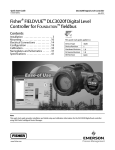
Instruction Manual
377 Trip Valve
D200319X012
July 2014
Fisherr 377 Trip Valve
Contents
Introduction . . . . . . . . . . . . . . . . . . . . . . . . . . . . . . . . . 1
Scope of Manual . . . . . . . . . . . . . . . . . . . . . . . . . . . . . 1
Description . . . . . . . . . . . . . . . . . . . . . . . . . . . . . . . . . 1
Specifications . . . . . . . . . . . . . . . . . . . . . . . . . . . . . . . 2
Educational Services . . . . . . . . . . . . . . . . . . . . . . . . . 2
Installation . . . . . . . . . . . . . . . . . . . . . . . . . . . . . . . . . . 4
Supply Pressure Requirements . . . . . . . . . . . . . . . . . 6
Operating Information . . . . . . . . . . . . . . . . . . . . . . . . . 8
Calibration . . . . . . . . . . . . . . . . . . . . . . . . . . . . . . . . . 8
Principle of Operation . . . . . . . . . . . . . . . . . . . . . . . . . 9
377D Trip Valve . . . . . . . . . . . . . . . . . . . . . . . . . . . . . 9
377L Trip Valve . . . . . . . . . . . . . . . . . . . . . . . . . . . . . 10
377U Trip Valve . . . . . . . . . . . . . . . . . . . . . . . . . . . . 11
Maintenance . . . . . . . . . . . . . . . . . . . . . . . . . . . . . . . . 12
Periodic Operational Check . . . . . . . . . . . . . . . . . . . 13
Trip Valve Part Replacement Procedures . . . . . . . . 13
Replacing Diaphragms and Valve Plug Parts . . . . . 13
Replacing Stem/Plug Assembly Parts . . . . . . . . . . . 14
Parts Ordering . . . . . . . . . . . . . . . . . . . . . . . . . . . . . . . 15
Parts Kits . . . . . . . . . . . . . . . . . . . . . . . . . . . . . . . . . . . 15
Parts List . . . . . . . . . . . . . . . . . . . . . . . . . . . . . . . . . . . 15
Figure 1. Fisher 377 Trip Valve Mounted on Size 130
585C Actuator
W8435‐1
Introduction
Scope of Manual
This instruction manual provides installation, operation, maintenance, and parts information for the Fisher 377 trip
valve. Refer to separate instruction manuals for information regarding the control valve, actuator, and accessories.
Do not install, operate, or maintain a 377 trip valve without being fully trained and qualified in valve, actuator and
accessory installation, operation, and maintenance. To avoid personal injury or property damage, it is important to
carefully read, understand, and follow all of the contents of this manual, including all safety cautions and warnings. If
you have any questions regarding these instructions contact your Emerson Process Management sales office before
proceeding.
Description
377 pressure‐sensing trip valves, shown in figures 1, 2, and 3, are for control applications where a specific
valve/actuator action is required when supply pressure falls below a specific point. When supply pressure falls below
the trip point, the trip valve cause the actuator to fail up, lock in the last position, or fail down. When the supply
pressure rises above the trip point, the 377 trip valve automatically resets, allowing the system to return to normal
operation. The trip valve can be top‐mounted on a manifold, yoke‐mounted, or bracket‐mounted to match the
application requirements. 377 trip valves are used with all types of piston actuators.
www.Fisher.com
Instruction Manual
377 Trip Valve
D200319X012
July 2014
Figure 2. Typical Fisher 377 Trip Valve
Figure 3. Simplified Sectional View of Trip Valve
UPPER
DIAPHRAGM
VALVE
PLUG SPRING
EXHAUST
PORT
SUPPLY
CONNECTION
RESTRICTION
LOWER
DIAPHRAGM
PORT D
PORT A
PORT E
PORT B
PLUG
ASSEMBLIES
W4292-1
W4303‐1
PORT F
PORT C
Specifications
Specifications for 377 trip valves are given in table 1.
Educational Services
For information on available courses for 377 trip valves, as well as a variety of other products, contact:
Emerson Process Management
Educational Services, Registration
Phone: +1- 641-754-3771 or +1-800-338-8158
e‐mail: [email protected]
http://www.emersonprocess.com/education
2
Instruction Manual
377 Trip Valve
D200319X012
July 2014
Table 1. Specifications
Pressure Connections
Available Configurations
377 Trip Valve: Includes check valve, but no volume
tank: user configured for locking position. For field
use or replacement.
When supply pressure falls below the trip point,
377D Trip Valve: Fails actuator piston down. Includes
check valve and volume tank.
377L Trip Valve: Locks actuator piston in the last
position.
377U Trip Valve: Fails actuator piston up. Includes
check valve and volume tank.
377CW Trip Valve: Fails fully clockwise to close valve.
Requires check valve and volume tank. Trip valve
moves piston to either up/down position and requires
actuator configuration for actual clockwise
movement.
377CCW Trip Valve: Fails fully counterclockwise to
close valve. Requires check valve and volume tank.
Trip valve moves piston to either up/down position
and requires actuator configuration for actual
counterclockwise movement.
All 377 Trip Valves can be converted to any of the
above fail modes with minor hookup changes
1/4 NPT internal
Temperature Capabilities(1)
Nitrile Diaphragms and O‐Rings: -40 to 82_C
(-40 to 180_F)
Fluorocarbon Diaphragms and O‐Rings: -18 to 104_C
(0 to 220_F)
Volume Tank Maximum Internal Working Pressure
(for 377D, 377U, 377CW and 377CCW trip valves)
Standard: 10.3 bar (150 psig) for non‐ASME approved
applications. See note on page 7.
ASME Approved Applications: Rated 10.3 bar (150
psig), maximum; 9.3 bar (135 psig), recommended.
See note on page 7.
Hazardous Area Classification
Complies with the requirements of ATEX Group II
Category 2 Gas and Dust
Allowable Supply Pressure for Trip Valve(1)
Maximum: 10.3 bar (150 psig)
Minimum: 3.8 bar (55 psig)
377 SST
Safety Instrumented System Classification
SIL 3 capable - certified by exida Consulting LLC
Outlet Pressure
Normal Operation: Pressure from control device
Fail‐Up or Fail‐Down Mode: Maximum volume tank
pressure
Lock‐In‐Last‐Position: Respective cylinder pressure
Mounting
Top‐Mounted: Manifold‐mounted between a Fisher
3570 positioner and 480 actuator (manifolds cannot
be supplied with Fisher 585C, 685, 1061, 1066, and
1069 piston actuators)
Side‐Mounted: Yoke‐mounted or bracket‐mounted
for use with a FIELDVUE™ DVC6200, DVC6200f,
DVC6200p, DVC6000 or DVC6000f digital valve
controller
Trip Point(2)
Adjustable from a minimum of 2.8 bar (40 psig) to a
maximum of 72 percent of supply pressure;
see figure 4
Reset: 12.5 to 33 percent above adjusted trip point
Approximate Weight
Trip Valve
Aluminum: 0.95 kg (2.1 pounds)
SST: 2.31 kg (5.1 pounds)
Mounting Manifold: 0.5 kg (1.2 pounds)
Volume Tank: Varies between 5.4 and 363 kg (12 and
800 pounds) depending on size
Flow Coefficients (Cv)(3)
Depends on flow path (shown in figure 3) as follows:
Port A to Port B and Port D to Port E: 0.5
Port B to Port C and Port E to Port F: 0.6
-continued-
3
Instruction Manual
377 Trip Valve
D200319X012
July 2014
Table 1. Specifications (continued)
Declaration of SEP
Fisher Controls International LLC declares this
product to be in compliance with Article 3 paragraph
3 of the Pressure Equipment Directive (PED) 97 / 23 /
EC. It was designed and manufactured in accordance
with Sound Engineering Practice (SEP) and cannot
bear the CE marking related to PED compliance.
However, the product may bear the CE marking to
indicate compliance with other applicable European
Community Directives.
1. The pressure/temperature limits in this document and any applicable standard or code limitation should not be exceeded.
2. If the trip point is not specified, the trip point is factory set at 72 percent of supply pressure or 2.8 bar (40 psig), whichever is higher.
3. Values represent nominal Cv measures for each port pair using a trip valve/actuator combination.
Figure 4. Maximum Trip Point Settings
SUPPLY PRESSURE, BAR
4
5
6
7
8
110
9
10.3
10
7.6
TRIP POINT, PSIG
90
6
2
80
MAXIMUM TRIP POINT
SETTING TO ENSURE
RESET 1
70
60
5
TRIP POINT, BAR
7
100
4
50
3
40
55 60
70
80
90
100 110 120 130 140 150
SUPPLY PRESSURE, PSIG
NOTES:
1
TRIP POINT MAY BE SET TO ANY VALUE BETWEEN 2.8 BAR (40 PSIG) AND THE MAXIMUM TRIP POINT LINE.
2
RESET OCCURS AT 12.5 TO 33 PERCENT ABOVE ADJUSTED TRIP POINT.
A2779‐2
Installation
WARNING
Avoid personal injury from sudden release of process pressure. Before mounting the controller:
D Always wear protective clothing, gloves, and eyewear when performing any installation operations to avoid personal
injury.
D Overpressuring any system component could result in personal injury or property damage due to fire and explosion
caused by venting or leakage of the supply medium. To avoid such injury or damage, provide suitable pressure‐relief or
pressure‐limiting devices if the supply pressure is capable of exceeding the maximum allowable pressure of the system
component.
D Check with your process or safety engineer for any additional measures that must be taken to protect against process
media.
D If installing into an existing application, also refer to the WARNING at the beginning of the Maintenance section in this
instruction manual.
The 377 trip valve is normally ordered as part of a control valve assembly. Follow the procedure in the appropriate
valve body and actuator instruction manual when installing the control valve in the piping.
4
Instruction Manual
377 Trip Valve
D200319X012
July 2014
If the 377 trip valve is shipped separately from the control valve assembly, the installation procedure depends upon
the type of actuator and accessory equipment required for the individual control valve system. Install any accessory
equipment in the control valve system so that the overall functioning of the specified trip valve pressure line
connections is not disrupted. Figures 7, 8, and 9 are schematics showing the pressure line connections for each of the
three possible fail‐mode configurations of the trip valve.
CAUTION
377 trip valves are leak tested to ensure that the intended actuator fail mode is maintained upon loss of supply pressure.
Control system accessories, such as volume boosters with hard seats, compromise the integrity of the entire system due to
leakage. Therefore, using control system accessories, such as volume boosters, between the trip valve and the actuator is
not recommended. If this cannot be avoided and a volume booster is required, a volume booster designed for tight shutoff,
such as the Fisher 2625, provides a higher probability of control system integrity. Refer to figures 5 and 6 for proper
installation of 377 trip valves with 2625 volume boosters.
Figure 5. Fisher 2625 Volume Booster used with 377U or 377D Trip Valve
1/2 O.D. TUBING
INPUT SIGNAL
1/2 O.D. COIL VOLUME
TANK TUBING
2625
3/4 NPT OR
1/2 NPT PIPING
PISTON
ACTUATOR
FISHER i2P-100/
67CFR
3/8 O.D.
TUBING
TYPICAL
377U 1
POSITIONER
VOLUME
TANK
3/4 NPT
CHECK VALVE
3/4 NPT OR
1/2 NPT PIPING
VENT
SUPPLY
NOTES:
1 THE HOOK UP OF PORT C AND F ARE REVERSED FOR 377D.
2. 3/4 NPT CHECK VALVE, 1/2 OR 3/4 NPT PIPING, AND 1/2‐INCH (OUTSIDE DIAMETER) COIL TUBING FOR THE VOLUME TANK ARE REQUIRED.
3. THE SUPPLY PRESSURE REGULATOR SPECIFIED MUST HAVE ADEQUATE CAPACITY FOR 2625 BOOSTERS. ALSO, IF THE 2625 BOOSTER IS TO BE NIPPLE MOUNTED, THE BOOSTER MUST BE
MOUNTED TO A 1/2 NPT OR LARGER CYLINDER CONNECTION. SOME SMALLER CYLINDERS CANNOT BE TAPPED THIS LARGE; CONTACT YOUR EMERSON PROCESS MANAGEMENT SALES OFFICE
FOR AVAILABILITY ON SPECIFIC TYPES AND SIZES.
E1570
5
Instruction Manual
377 Trip Valve
D200319X012
July 2014
Figure 6. Fisher 2625 Volume Booster used with 377L Trip Valve
INPUT SIGNAL
1/2 O.D. TUBING
2625
3/4 NPT OR
1/2 NPT PIPING
PISTON
ACTUATOR
i2P-100/67CFR
3/8 O.D.
TUBING
TYPICAL
377L
POSITIONER
3/4 NPT
CHECK VALVE
3/4 NPT OR
1/2 NPT PIPING
SUPPLY
NOTES:
1. 3/4 NPT CHECK VALVE AND 1/2 OR 3/4 NPT PIPING ARE REQUIRED.
2. THE SUPPLY PRESSURE REGULATOR SPECIFIED MUST HAVE ADEQUATE CAPACITY FOR 2625 BOOSTERS. ALSO, IF THE 2625 BOOSTER IS TO BE NIPPLE MOUNTED, THE BOOSTER MUST
BE MOUNTED TO A 1/2 NPT OR LARGER CYLINDER CONNECTION. SOME SMALLER CYLINDERS CANNOT BE TAPPED THIS LARGE; CONTACT YOUR EMERSON PROCESS MANAGEMENT
SALES OFFICE FOR AVAILABILITY ON SPECIFIC TYPES AND SIZES.
E1571
Supply Pressure Requirements
WARNING
Severe personal injury or property damage may occur if the instrument air supply is not clean, dry, and oil free. While use
and regular maintenance of of a filter that removes particles larger than 40 micrometers in diameter will suffice in most
applications, check with an Emerson Process Management field office and instrument industry air quality standards for use
with corrosive gas or if you are unsure about the proper amount or method of air filtration or filter maintenance.
A supply regulator, if used, must have a flow capacity greater than the required combined capacity of the trip valve and
actuator. In order to ensure proper selection of a supply regulator, be sure the Cv value of the regulator is greater than
the appropriate flow path Cv value listed in table 1 for the trip valve. A regulator with insufficient capacity may allow
supply pressure to droop, which can cause the trip valve to trip again and begin a trip‐reset cycle. An example of an
appropriate supply regulator to use with a 377 trip valve is a 64 regulator; its capacity is usually great enough to meet
the demands of most trip valve/actuator combinations. Determine the requirements of your trip valve/actuator
combination for proper selection of a supply regulator.
6
Instruction Manual
377 Trip Valve
D200319X012
July 2014
Note
During normal operation, an adequately sized supply regulator maintains a greater supply pressure than the pressure demand of
the trip valve and control devices. However, if the normal actuator piston position is not relatively close to the actuator piston fail
position during startup, or during the restoration of supply pressure, the regulator supply pressure may droop and cause the trip
valve to trip again and begin a trip‐reset cycle. To prevent this, perform the following steps:
1. Adjust the instrument (control device) pressure to position the actuator piston as it is positioned in the fail mode.
2. Restore the supply pressure to the normal operating range.
3. Manually reset the instrument pressure for normal operation.
WARNING
If a flammable or hazardous gas is used as the supply pressure medium, personal injury or property damage could result
from fire or explosion of accumulated gas or from contact with hazardous gas. The positioner/ actuator assembly does not
form a gas‐tight seal, and when the assembly is enclosed, a remote vent line, adequate ventilation, and necessary safety
measures should be used. However, a remote vent pipe alone cannot be relied upon to remove all hazardous gas. Vent line
piping should comply with local and regional codes and should be as short as possible with adequate inside diameter and
few bends to reduce case pressure buildup.
Note
To ensure trip system integrity upon loss of supply pressure, a 377D or 377U trip system requires a volume tank and check valve as
shown in figures 7 and 9.
State and local regulations may require the use of ASME approved volume tanks. Determine requirements and applicable
regulations for proper volume tank selection.
For ASME approved applications, the volume tank is rated at 10.3 bar (150 psig) internal working pressure, and has a safety valve
with a 10.3 bar (150 psig) set pressure mounted on the volume tank for pressure relief. Avoid supply pressure too near the safety
valve set pressure. To ensure safety valve seat tightness and longevity, the recommended maximum supply pressure is 9.3 bar
(135 psig).
Standard volume tanks supplied in Europe must conform to Directive 2009/105/EC for simple pressure vessels. The maximum
pressure rating is stated on the tank.
For standard applications (not ASME approved), a DOT tank is used. This tank is rated at 14.5 bar (240 psig) in LP service. When
used with air, the rating should be considered to be 10.3 bar (150 psig), consistent with the maximum pressure allowed for the
377 trip valve.
1. Before installing the trip valve, inspect it to be sure it is free of any foreign material.
2. Be sure all connecting tubing is free of foreign material.
3. Use acceptable piping practices when installing the trip valve. Coat all external threaded connections with a pipe
compound.
CAUTION
To avoid damage and possible operational impairment to the trip valve, be careful not to get excessive pipe compound on
the connections. Excess compound could result in improper pilot and cylinder valve operation.
7
377 Trip Valve
July 2014
Instruction Manual
D200319X012
CAUTION
To ensure the integrity of control systems utilizing a 2625 volume booster in conjunction with a 377 trip valve, apply supply
pressure to the volume booster and to the volume tank (volume tank not required on 377L trip valve) through a check
valve. Failure to install the check valve properly will allow the cylinder pressure to bleed back through the open volume
booster supply port upon loss of supply pressure. The actuator may not fail as intended.
WARNING
Personal injury or property damage could result from bursting of parts due to temperature fluctuations or extreme heat. If
temperature fluctuations or extreme heat cannot be avoided, use a relief valve to protect the volume tank.
4. Read the following information before making pressure connections:
a. Trip valve port A must receive the operating pressure that is intended for the top of the actuator cylinder.
Depending on the actuator type and accessories being used, this operating pressure will be from a valve
positioner or switching solenoid.
b. Trip valve port B must provide operating pressure to the top of the actuator cylinder. Depending on the actuator
type and accessories being used, connect this port to the manifold assembly, to the top of the cylinder, or to the
cylinder connection on the hydraulic snubber (if one is used).
c. Trip valve port C must provide a fail‐mode outlet for the operating pressure to or from the top of the actuator
cylinder. For the fail‐down mode, connect this port to the volume tank. For the fail‐up mode, vent this port to
atmosphere. For the lock‐in‐last‐position mode, plug this port.
d. Trip valve port D must receive the operating pressure that is intended for the bottom of the actuator cylinder.
Depending on the actuator type and accessories being used, this operating pressure will be from a valve
positioner or switching solenoid.
e. Trip valve port E must provide operating pressure to the bottom of the actuator cylinder. Always connect this
port to the bottom of the actuator cylinder.
f. Trip valve port F must provide a fail‐mode outlet for the operating pressure to or from the bottom of the actuator
cylinder. For the fail‐down mode, vent this port to atmosphere. For the fail‐up mode, connect this port to the
volume tank. For the lock‐in‐last‐position mode, plug this port.
Operating Information
Calibration
This calibration procedure assumes that the trip valve is mounted on the actuator (or other device) and that all piping
and the appropriate volume tank (if necessary ) are installed. All key numbers refer to figure 10. For the appropriate
fail‐mode schematic, see figure 7, 8, or 9.
WARNING
The following procedure requires taking the trip valve out of service. To avoid personal injury and property damage by an
uncontrolled process medium, provide some temporary means of control of the process medium while the trip valve is out
of service.
8
Instruction Manual
D200319X012
377 Trip Valve
July 2014
1. Remove the adjusting screw cap (key 1).
2. Loosen the hex nut (key 3), and turn the set screw (key 2) counterclockwise until all loading is removed from the
spring (key 6).
3. Connect an adequately sized gauge for the supply pressure reading to the supply line. To make the fail action more
visible, adjust the control device signal so that actuator stem movement is visible when the trip valve is actuated.
4. For the lock‐in‐last‐position mode, remove the plugs from ports C and F.
5. Set the supply pressure at the required trip point pressure (refer to table 1 for the trip point limits).
Note
For proper calibration, completely back out the set screw (key 2) until there is no spring compression. Then, set the trip point by
turning the set screw clockwise to compress the spring.
6. Slowly turn the set screw clockwise to compress the spring until the trip valve trips. When the trip valve trips in the
fail‐up or fail‐down mode, the actuator stem moves to the appropriate position. In the lock‐in‐last‐position mode,
the actuator stem does not move, however, air will be heard escaping from ports C and F. This is because pressure is
being released from both sides of the actuator cylinder.
7. Tighten the hex nut (key 3), and install the adjusting screw cap (key 1).
8. For the lock‐in‐last‐position mode, reinstall the plugs in ports C and F.
9. Reset the control device for normal operation.
Principle of Operation
377D Trip Valve
Figure 7 illustrates trip valve operation in the fail‐down mode.
In normal operation, supply pressure loads the upper diaphragm of the trip valve. The valve plug spring keeps the
exhaust port closed. Supply pressure also loads the lower diaphragm through the restriction, causing the plug
assemblies to move down and isolate ports C and F while connecting port A to B and port D to E. Normal actuator
control pressure from the control device is applied to the top of the cylinder through ports A and B and to the bottom
of the cylinder through ports D and E. A volume tank is charged to the maximum supply pressure through a check
valve. The check valve maintains maximum supply pressure in the volume tank if the supply pressure drops.
When the supply pressure falls below the trip point, the exhaust port opens venting the supply pressure that is loading
the lower diaphragm. This causes the upper ports of the plug assemblies to close and disconnect normal pressure from
the control device to the actuator.
Volume tank pressure is then applied through ports C and B to the top of the actuator cylinder, while pressure in the
bottom of the actuator cylinder is vented through ports E and F. The pressure imbalance created forces the actuator
piston down.
When supply pressure is restored, it again loads the upper and lower diaphragms causing the trip valve to reset. The
exhaust port closes, the upper ports of the plug assemblies open, and the lower ports close. Normal actuator control
pressure from the control device is restored through ports A and B and ports D and E. The check valve opens and
recharges the volume tank to the maximum supply pressure.
9
Instruction Manual
377 Trip Valve
D200319X012
July 2014
Figure 7. Fisher 377D Trip Valve Shown in Tripped Condition
MAIN SPRING
SPRING
ACTUATOR
VALVE PLUG
VENT
UPPER
DIAPHRAGM
CONTROL
DEVICE
EXHAUST
PORT
SUPPLY
PRESSURE
DVC6200
LOWER
DIAPHRAGM
PORT A
CHECK
VALVE
PORT D
PORT B
PORT E
UPPER PORTS
LOWER
PORTS
PORT F
PLUG
ASSEMBLIES
VOLUME
TANK
PORT C
SUPPLY PRESSURE
CONTROL PRESSURE TO TOP OF CYLINDER (BLOCKED)
CONTROL PRESSURE TO TOP BOTTOM OF CYLINDER (BLOCKED)
PRESSURE TO TOP OF CYLINDER (FROM VOLUME TANK)
PRESSURE FROM BOTTOM OF CYLINDER (VENTING)
LOWER DIAPHRAGM LOADING PRESSURE (BEING VENTED)
GE08412‐A
A6905‐1
377L Trip Valve
Figure 8 illustrates trip valve operation in the lock‐in‐last‐position mode.
When supply pressure falls below the trip point, the exhaust port opens venting supply pressure from the lower
diaphragm. This causes the upper ports of the plug assemblies to close and the lower ports to open. Because ports C
and F are plugged, no pressure change occurs on either side of the actuator piston and the piston is pressure‐locked in
position. No volume tank is necessary in this mode.
When supply pressure is restored, the plug assemblies move back into the normal operating position. Supply pressure
from the control device is applied to the actuator through ports A and B and ports D and E.
10
Instruction Manual
377 Trip Valve
D200319X012
July 2014
Figure 8. Fisher 377L Trip Valve Shown in Tripped Condition
MAIN SPRING
ACTUATOR
SPRING
VALVE PLUG
VENT
UPPER DIAPHRAGM
EXHAUST
PORT
SUPPLY
PRESSURE
DVC6200
LOWER
DIAPHRAGM
PORT A
CONTROL
DEVICE
PORT D
PORT B
PORT E
UPPER PORTS
LOWER PORTS
PORT F
PORT C
PLUG
ASSEMBLIES
SUPPLY PRESSURE
PRESSURE TO TOP OF CYLINDER (STATIC)
CONTROL PRESSURE TO TOP OF CYLINDER (BLOCKED)
PRESSURE FROM BOTTOM OF CYLINDER (STATIC)
CONTROL PRESSURE TO TOP BOTTOM OF CYLINDER (BLOCKED)
LOWER DIAPHRAGM LOADING PRESSURE (BEING VENTED)
GE08414‐A
A6906-1
377U Trip Valve
Figure 9 illustrates trip valve operation in the fail‐up mode. The fail‐up mode of operation is similar to the fail‐down
mode of operation except that the connections to port C and F are reversed. When supply pressure falls below the trip
point, the top of the actuator cylinder vents, and volume tank pressure loads the bottom of the actuator cylinder. The
pressure imbalance created forces the actuator piston up.
11
Instruction Manual
377 Trip Valve
D200319X012
July 2014
Figure 9. Fisher 377U Trip Valve Shown in Tripped Condition
MAIN SPRING
ACTUATOR
SPRING
VALVE PLUG
VENT
UPPER DIAPHRAGM
CONTROL
DEVICE
EXHAUST
PORT
SUPPLY
PRESSURE
DVC6200
LOWER
DIAPHRAGM
PORT D
PORT E
PORT A
CHECK
VALVE
PORT B
UPPER
PORTS
LOWER PORTS
PLUG ASSEMBLIES
VOLUME
TANK
PORT F
PORT C
SUPPLY PRESSURE
PRESSURE TO TOP OF CYLINDER (VENTING)
CONTROL PRESSURE TO TOP OF CYLINDER (BLOCKED)
PRESSURE FROM BOTTOM OF CYLINDER (FROM VOLUME TANK)
CONTROL PRESSURE TO TOP BOTTOM OF CYLINDER (BLOCKED)
LOWER DIAPHRAGM LOADING PRESSURE (BEING VENTED)
GE08413‐A
A2284‐6
Maintenance
Trip valve parts are subject to normal wear so the trip valve must be actuated periodically to determine if it is working
properly. If the trip valve does not work properly, use the following procedures to inspect and repair or replace parts as
necessary. The frequency of inspection and repair or replacement depends upon the severity of service conditions. Be
sure to note the location of all pressure connections to ensure proper trip valve installation upon reassembly, or use
the installation procedures in this instruction manual. All key numbers refer to figure 10 unless otherwise indicated.
WARNING
Avoid personal injury or property damage from sudden release of process pressure or bursting of parts. Before performing
any maintenance operations:
D Always wear protective clothing, gloves, and eyewear when performing any maintenance operations to avoid personal
injury.
D Do not remove the actuator from the valve while the valve is still pressurized.
12
Instruction Manual
377 Trip Valve
D200319X012
July 2014
D Disconnect any operating lines providing air pressure, electric power, or a control signal to the actuator. Be sure the
actuator cannot suddenly open or close the valve.
D Use bypass valves or completely shut off the process to isolate the valve from process pressure. Relieve process pressure
from both sides of the valve. Drain the process media from both sides of the valve.
D Vent the power actuator loading pressure and relieve any actuator spring precompression.
D Use lock‐out procedures to be sure that the above measures stay in effect while you work on the equipment.
D Check with your process or safety engineer for any additional measures that must be taken to protect against process
media.
Periodic Operational Check
WARNING
The following procedure requires taking the trip valve out of service. To avoid personal injury and property damage by
uncontrolled process medium, provide some temporary means of control of the process medium while the trip valve is out
of service.
1. Isolate the actuator/valve assembly from the process loop.
2. Provide a means of monitoring the supply pressure input to the trip valve.
3. Starting with normal supply pressure applied to the trip valve, slowly reduce the supply pressure until the trip valve
trips. The trip valve should trip at the pressure set during the calibration procedures.
4. Increase the supply pressure until the trip valve resets. This should occur at a supply pressure 12.5 to 33 percent
above the trip point.
5. If the trip valve fails to trip and reset at the calibrated settings, refer to the calibration procedures.
6. If the trip valve will not calibrate, continue with the following maintenance procedures.
Trip Valve Part Replacement Procedures
WARNING
Refer to the WARNING at the beginning of the Maintenance Section in this instruction manual.
Isolate the control valve from the line pressure, release pressure from both sides of the valve body, and drain the
process media from both sides of the valve. If using a power actuator, also shut off all pressure lines to the power
actuator, release all pressure from the actuator. Use lock‐out procedures to be sure that the above measures stay in
effect while you work on the equipment.
Replacing Diaphragms and Valve Plug Parts
CAUTION
Care must be taken during the following procedure to prevent damage to the upper diaphragm.
13
377 Trip Valve
July 2014
Instruction Manual
D200319X012
1. Remove the adjusting screw cap (key 1), and loosen the hex nut (key 3) that locks the set screw (key 2). Loosen the
set screw to remove all spring compression.
2. Remove the cap screws (key 7, not shown) from the spring case, and lift off the body assembly (key 16) and
attached parts from the trip valve body (key 21). Note the orientation of the vent and supply connections to the
body (see figure 1).
3. Remove the cap screws (key 20, not shown) and separate the diaphragm (key 17), diaphragm spacer (key 19), and
the pusher plate (key 18) from the rest of the body assembly. Lift off the spring case (key 4), travel stop (key 75,
aluminum housing only), upper spring seat (key 5), and spring (key 6).
4. Take out the upper diaphragm assembly (keys 8, 9, 10, 11, 12, 13, 14, and 15).
5. Carefully unscrew the spring seat (key 9) from the upper diaphragm retainer (key 13). Be careful not to lose the
valve plug (key 14), valve guide (key 8), and spring (key 10). Also be careful not to damage the upper diaphragm
(key 12).
6. Inspect the upper diaphragm, valve plug, body assembly, and O‐ring (key 15) for nicks, scratches, or cuts that could
cause leakage. Replace parts as necessary. Make sure the O‐ring (key 15) is properly lubricated (key 77) to avoid
leakage past the O‐ring.
7. With the spring (key 10), spring seat (key 9), valve plug (key 13), valve guide (key 8), diaphragm washer (key 11),
and upper diaphragm (key 12) in place, screw the upper diaphragm retainer (key 13) and spring seat (key 9)
together, being careful not to damage the diaphragm.
8. Inspect the lower diaphragm (key 17) and pusher plate (key 18), and replace them if damaged or excessively worn.
9. Place the upper diaphragm assembly (keys 8, 9, 10, 11, 12, 13, 14, and 15), travel stop (key 75, aluminum housing
only), spring (key 6), upper spring seat (key 5), diaphragm spacer (key 19), pusher plate (key 18), and diaphragm
(key 17) onto the body assembly (key 16). Secure the body assembly parts to the spring case (key 4) with the cap
screws (key 20). Position the supply and vent connections as noted in step 2.
10. Note the orientation of the supply connection to the body (see figure 1). Attach the assembly, from step 9, to the
body (key 21) with the cap screws (key 7, not shown). Tighten the screws.
11. Refer to the installation and calibration procedures.
Replacing Stem/Plug Assembly Parts
1. Remove the cap screws (key 76, not shown) from the body (key 21), and remove the manifold (key 73) and the
stem/plug assemblies (keys 22, 23, 24, 26, and 27).
2. Inspect the upper and lower O‐rings (keys 23 and 26) for nicks or wear. If the lower O‐ring needs to be replaced,
remove the O‐ring retainer screw (key 27) before installing the new O‐ring. The upper O‐ring simply slips over the
end of the stem (key 22). Lightly lubricate O-rings (key 77) prior to reassembly.
3. Inspect the stem/plug assemblies, inspect the valve seats in the body (key 21), and replace any parts if necessary.
4. When stem/plug assembly maintenance procedures are complete, carefully slide the stem/plug assemblies
(keys 22, 23, 24, 26, and 27) and springs (key 25) into the body. Attach the manifold (key 73) to the bottom of the
body (key 21), and tighten the screws (key 76).
5. Refer to the installation and calibration procedures.
14
Instruction Manual
377 Trip Valve
D200319X012
July 2014
Parts Ordering
When corresponding with your Emerson Process Management sales office about this equipment, always refer to the
trip valve serial number which is located on the nameplate. Refer to table 2 for common parts. Contact your Emerson
Process Management sales office if part numbers are needed.
WARNING
Use only genuine Fisher replacement parts. Components that are not supplied by Emerson Process Management should
not, under any circumstances, be used in any Fisher trip valve. Use of components not supplied by Emerson Process
Management may void your warranty, might adversely affect the performance of the instrument, and could cause personal
injury and property damage.
Parts Kits
Description
Part Number
Repair Kit
Kit include valve plugs, stems, plug assemblies, and nitrile
diaphragms, O‐rings, and gasket (keys 12, 14, 15, 17, 22,
23, 24, 26, 29, 63, 74, and 89).
Aluminum Construction
R377X000012
Stainless Construction
R377X000032
Parts List
Table 2. Common Parts
MATERIAL
KEY
NUMBER
DESCRIPTION
QUANTITY
REQUIRED
Trip Valve Construction
Aluminum
Stainless Steel
1
Adjusting screw cap
Plastic
Plastic
2
Set screw
Pl steel
S31600 (316 SST)
3
Hex nut
Pl steel
S31600
4
Spring case
Aluminum
CF3M SST casting
(316L SST, cast)
5
Upper spring seat
Pl steel
S31600
6
Spring
Pl steel
S30200 (302 SST)
7
Cap screw (not shown)
Pl steel
S31600
8
Valve guide
Anodized aluminum/TFE
S31603 (316L SST)
9
Spring, seat
Aluminum
Stainless steel
10
Spring
Pl steel
S30200
11
Diaphragm washer
Aluminum
Stainless steel
12
Diaphragm
Nitrile(1)
Fluorocarbon
Nitrile(1)
Fluorocarbon
13
Diaphragm retainer
Anodized aluminum/TFE
S31603
Valve plug
Brass/nitrile(1)
Brass/fluorocarbon
SST/nitrile(1)
SST/fluorocarbon
14
4
1. Included in Repair Kit
-continued-
15
Instruction Manual
377 Trip Valve
D200319X012
July 2014
Table 2. Common Parts (continued)
PART MATERIAL
KEY
NUMBER
DESCRIPTION
QUANTITY
REQUIRED
Trip Valve Construction
Aluminum
Stainless Steel
15
O‐ring
Nitrile(1)
Fluorocarbon
16
Pilot body assembly
Aluminum/anodized aluminum
CF3M SST casting
(316L SST, cast)
17
Diaphragm
Nitrile(1)
Fluorocarbon
Nitrile(1)
Fluorocarbon
18
Pusher plate
Aluminum
S31603 (316L SST)
19
Diaphragm spacer
Aluminum
CF3M SST casting
20
Cap screw (not shown)
Pl steel
S31600 (316 SST)
21
Body
Aluminum
CF3M SST casting
22
Stem(1)
2
Stainless steel
S31603
Nitrile(1)
Fluorocarbon
4
Nitrile(1)
Fluorocarbon
23
O‐ring
2
Nitrile(1)
Fluorocarbon
24
Plug assembly
2
Brass/chloroprene(1)
Brass/fluorocarbon
S31603/chloroprene
S31603/fluorocarbon
25
Spring
2
Pl steel
S30200 (302 SST)
Nitrile(1)
Fluorocarbon
26
O‐ring
2
Nitrile(1)
Fluorocarbon
27
O‐ring retainer screw
2
Stainless steel
S30300 (303 SST)
Nitrile(1)
Fluorocarbon
Nitrile(1)
Fluorocarbon
Pl steel
Stainless steel
Aluminum
Aluminum
Pl steel
Stainless steel
Steel
Stainless steel
Brass, use with all actuators except 1069
S31600, use with 1069 actuator
S31600
29
O‐ring (top‐mounted only)
2
30
Cap screw
top mounted
yoke mounted
bracket mounted
2
1
1
31
Manifold assembly
32
Cap screw (use w/manifold assembly)
(not shown)
33
Cap screw (not shown)
yoke mounted
bracket mounted
34
Pipe plug (for 377L only) (not shown)
35
Pipe plug (boss or bracket mounted w/o manifold
assembly for 480‐16 only) (not shown)
Pl steel
Stainless steel
36
Check valve, (for 377D, 377U 377CW
and 377CCW only) (not shown)
For use w/o 2625
For use with 2625
Brass or S31600
S31600
Plastic
Plastic
Stainless steel
Stainless steel
2
2
Vent assembly (not shown)
37
Top mounted 377D, 377U 377CW
and 377CCW
Top or boss mounted 377D, 377U
377CW and 377CCW with flow control valve
Boss mounted 377D, 377L, 377U,
377CW and 377CCW
37
Flow control valve (optional on 377D, 377U 377CW
and 377CCW trip valves)
39
Lithium grease (not furnished with trip valve)
1
1
2
1. Included in Repair Kit
-continued-
16
Instruction Manual
377 Trip Valve
D200319X012
July 2014
Table 2. Common Parts (continued)
PART MATERIAL
KEY
NUMBER
DESCRIPTION
44
Volume Tank (for 377D, 377U, 377CW, and 377CCW
only) (not shown)
Standard
11.8 L / 721 inch3 / 3.1 gal
21.6 L / 1315 inch3 / 5.7 gal
32.3 L / 1970 inch3 / 8.5 gal
42.9 L / 2615 inch3 / 11.3 gal
65.6 L / 4001 inch3 / 17.3 gal
131 L / 8002 inch3 / 34.6 gal
(requires two 4001 inch3 volume tanks)
ASME Approved (use w/safety valve)
Canadian Registered
8.5L / 518 inch3 / 2.2 gal
24.9 L / 1520 inch3 / 6.6 gal
30.0 L / 1831 inch3 / 7.9 gal
42.8 L / 2609 inch3 / 11.3 gal
68.8 L / 4199 inch3 / 18.1 gal
71.6L / 4371 inch3 / 18.9 gal
143.3 L / 8742 inch3 / 37.86 gal
(requires two 4371 inch3 volume tanks)
114 L / 6930 inch3 / 30 gal
227 L / 13860 inch3 / 60 gal
303 L / 18480 inch3 / 80 gal
454 L / 27720 inch3 / 120 gal
908 L / 55440 inch3 / 240 gal
45
Pipe bushing
For standard volume tanks w/o 2625
For standard volume tanks w/2625 or
ASME approved volume tanks
46
47
48
QUANTITY
REQUIRED
1 req'd per
volume
tank
Pipe tee
For two standard volume tanks w/o 2625
For two standard volume tanks w/2625 or
two ASME approved volume tanks
For one ASME approved volume tank w/o 2625
For one ASME approved volume tank w/2625
Pipe nipple
For two standard volume tanks w/o 2625
For two standard volume tanks w/2625 or
two ASME approved volume tanks or
one ASME approved volume tank w/o 2625
For one ASME approved volume tank w/26252
Safety valve, for ASME approved volume tanks
49
Connector
For two standard volume tanks w/o 2625
For two standard volume tanks w/2625 or
two ASME approved volume tanks
51
Volume tank tubing
7.6 m (25 foot) coil
1/4 O.D.
1/2 O.D
61
Pipe cross, for two ASME approved volume tanks only
2
Trip Valve Construction
Aluminum
Stainless Steel
Alloy steel
S31600 (316 SST)
Pl steel
S31600
Galvanized iron
S31600
Galvanized steel
S31600
Brass and steel
S31600
Brass
S31600
Copper
S31600
S31600
63
O‐ring (use w/manifold assembly)
Nitrile(1)
Fluorocarbon
64
Screen (not shown)
For top mounted 377D, 377U, 377L, 377CW
and 377CCW (2 req'd)
For 377D ,377U, 377CW or 377CCW with
speed control valve (1 req'd)
Stainless steel
Nitrile(1)
Fluorocarbon
Stainless steel
1. Included in Repair Kit
-continued-
17
Instruction Manual
377 Trip Valve
D200319X012
July 2014
Table 2. Common Parts (continued)
PART MATERIAL
KEY
NUMBER
65
71
DESCRIPTION
QUANTITY
REQUIRED
Screen (not shown)
For boss mounted 377D, 377U, 377CW or
377CCW
Spring retainer spacer (use w/ manifold assembly)
(not shown)
Trip Valve Construction
Aluminum
Stainless Steel
Stainless steel
Stainless steel
Stainless steel
Stainless steel
Aluminum
CF3M SST casting
(316L SST, cast)
Nitrile(1)
Fluorocarbon
Nitrile(1)
Fluorocarbon
Pl steel
(2)
2
Pl steel
S31600 (316 SST)
73
Manifold
74
O‐ring
75
Travel stop
76
Cap screw (not shown)
77
Silicone‐based lubricant (not furnished with trip valve)
78
Cap Screw (not shown), Bracket mounted
2
Pl steel
Stainless steel
79
Lockwasher (not shown), Bracket mounted
4
Pl steel
Stainless steel
80
Hex nut (not shown), Bracket mounted
2
Pl steel
Stainless steel
88
Washer (not shown), Bracket mounted
2
Pl steel
Stainless steel
Nitrile nylon(1)
Polyacrylate/nylon
Pl steel
Nitrile nylon(1)
Polyacrylate/nylon
Stainless steel
89
95
Gasket
Standard
High temperature
Mounting plate (not shown), Bracket mounted
2
1. Included in Repair Kit
2. Not required for stainless steel trip valve.
Fittings
Description
Note
The following is a list of tubing fittings and pipe fittings used for trip
valve installation. Key numbers and quantities are not shown due to the
variations in piping arrangements possible. To order replacement
fittings, determine the part name, size, and number of replacements
required and contact your Emerson Process Management sales office.
Pipe Nipple, galvanized or stainless steel
1/4 NPT
3/4 NPT
Connector, brass or stainless steel
1/4 NPT x 1/4 O.D.
1/4 NPT x 3/8 O.D.
1/2 NPT x 1/2 O.D.
Elbow, brass or stainless steel
1/4 NPT x 3/8 O.D.
18
Description
Pipe cross, galvanized iron or stainless steel
1/4 NPT
3/4 NPT
Pipe Tee, galvanized iron or stainless steel
1/4 NPT
3/4 NPT
Pipe Bushing, plated or stainless steel
3/4 NPT x 1/4 NPT
3/4 NPT x 1/2 NPT
Instruction Manual
377 Trip Valve
D200319X012
July 2014
Figure 10. Trip Valve Assembly
NOTE: KEY NUMBERS 7, 20, 64, 65, 76, 78, 79, 80, 88 NOT SHOWN
APPLY LUB
NOTE: KEY NUMBERS 7, 20, 30, 33, 36, 37, 64, 65, 76, 78, 79, 80, 88 NOT SHOWN
APPLY LUB
GE51600-A
49A3195-C
ALUMINUM CONSTRUCTION
STAINLESS STEEL CONSTRUCTION
19
377 Trip Valve
July 2014
Instruction Manual
D200319X012
Neither Emerson, Emerson Process Management, nor any of their affiliated entities assumes responsibility for the selection, use or maintenance
of any product. Responsibility for proper selection, use, and maintenance of any product remains solely with the purchaser and end user.
Fisher and FIELDUVE are marks owned by one of the companies in the Emerson Process Management business unit of Emerson Electric Co. Emerson Process
Management, Emerson, and the Emerson logo are trademarks and service marks of Emerson Electric Co. All other marks are the property of their respective
owners.
The contents of this publication are presented for informational purposes only, and while every effort has been made to ensure their accuracy, they are not
to be construed as warranties or guarantees, express or implied, regarding the products or services described herein or their use or applicability. All sales are
governed by our terms and conditions, which are available upon request. We reserve the right to modify or improve the designs or specifications of such
products at any time without notice.
Emerson Process Management
Marshalltown, Iowa 50158 USA
Sorocaba, 18087 Brazil
Chatham, Kent ME4 4QZ UK
Dubai, United Arab Emirates
Singapore 128461 Singapore
www.Fisher.com
20
E 1984, 2014 Fisher Controls International LLC. All rights reserved.