1
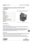
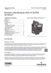
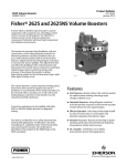
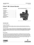
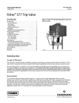
Instruction Manual
2625 and 2625NS Volume Booster
D100348X012
January 2015
Fisherr 2625 and 2625NS Volume Boosters
Contents
Introduction . . . . . . . . . . . . . . . . . . . . . . . . . . . . . . . . . 1
Scope of Manual . . . . . . . . . . . . . . . . . . . . . . . . . . . . . . 1
Description . . . . . . . . . . . . . . . . . . . . . . . . . . . . . . . . . . 1
Specifications . . . . . . . . . . . . . . . . . . . . . . . . . . . . . . . . 2
Educational Services . . . . . . . . . . . . . . . . . . . . . . . . . . . 3
Installation . . . . . . . . . . . . . . . . . . . . . . . . . . . . . . . . . . 4
Mounting . . . . . . . . . . . . . . . . . . . . . . . . . . . . . . . . . . 4
Pressure Connections . . . . . . . . . . . . . . . . . . . . . . . . 5
Diagnostic Connections . . . . . . . . . . . . . . . . . . . . . . 6
Supply Pressure . . . . . . . . . . . . . . . . . . . . . . . . . . . . . 6
Exhaust Ports . . . . . . . . . . . . . . . . . . . . . . . . . . . . . . . 7
Operating Information . . . . . . . . . . . . . . . . . . . . . . . . . 7
Principle of Operation . . . . . . . . . . . . . . . . . . . . . . . . . 7
Maintenance . . . . . . . . . . . . . . . . . . . . . . . . . . . . . . . . . 8
Diaphragm Assembly Replacement . . . . . . . . . . . . . 8
Valve Assembly Replacement . . . . . . . . . . . . . . . . . . 9
Installation of Diagnostic Connections . . . . . . . . . 10
Parts Ordering . . . . . . . . . . . . . . . . . . . . . . . . . . . . . . . 11
Parts Kits . . . . . . . . . . . . . . . . . . . . . . . . . . . . . . . . . . . 11
Parts List . . . . . . . . . . . . . . . . . . . . . . . . . . . . . . . . . . . 11
Figure 1. Fisher 2625 Volume Booster
W4727-1
Introduction
Scope of Manual
This instruction manual provides installation, operation, maintenance, and parts information for Fisher 2625 and
2625NS volume boosters (figure 1). Refer to separate instruction manuals for information regarding the valve body,
actuator, and other accessories.
Do not install, operate, or maintain a 2625 or 2625NS volume booster without being fully trained and qualified in
valve, actuator, and accessory installation, operation, and maintenance. To avoid personal injury or property damage,
it is important to carefully read, understand, and follow all of the contents of this manual, including all safety cautions
and warnings. If you have any questions regarding these instructions contact your Emerson Process Management sales
office before proceeding.
Description
The 2625 is certified for use in Safety Instrumented System (SIS) applications. Certification is by EXIDA Consulting LLC,
a global provider of functional safety and control system security. SIS certification is identified on the product by the
EXIDA logo on the 2625 nameplate.
The 2625 and 2625NS volume boosters are used in conjunction with a positioner on a throttling control valve to
increase stroking speed. The booster has a fixed deadband (controlled by the seat‐to‐seat dimension of the supply and
www.Fisher.com
2625 and 2625NS Volume Booster
January 2015
Instruction Manual
D100348X012
exhaust plugs) which is factory set during assembly and testing. In addition, the booster incorporates soft‐seat
construction and an integral bypass restriction to eliminate positioner saturation problems that can occur with volume
boosters that do not have these features. Adjustment of the integral bypass restriction is necessary for system
stability. This adjustment does not affect the deadband of the booster, but does permit the control valve to respond to
small input signal changes from the positioner without sacrificing steady‐state accuracy.
It also allows the booster to deliver high‐volume output for fast stroking when large, rapid input signal changes occur.
The volume booster is used to improve stroking speed. If precision valve control is required, the use of a positioner is
recommended. If you use the volume booster only with an actuator, for on‐off control, the integral bypass restriction
on the volume booster must be closed (turned fully clockwise).
To facilitate diagnostic testing, you can install connectors and piping with each 2625 and 2625NS volume booster.
The 2625NS volume booster is designed for nuclear power applications. The 2625NS construction includes materials
that provide superior performance at elevated temperature and radiation levels.
The O‐rings in the 2625NS are EPDM (ethylene propylene) and the diaphragms are EPDM/meta‐aramid. EPDM
demonstrates superior temperature capability and shelf life over nitrile. The meta‐aramid diaphragm fabric
demonstrates improved strength retention at elevated temperature and radiation conditions.
CAUTION
Use a clean, dry, oil‐free air supply with instruments containing EPDM components. EPDM is subject to degradation when
exposed to petroleum based lubricants.
Under the 10CFR50, Appendix B, quality assurance program, the 2625NS volume booster is qualified “commercial
grade dedicated”. These can be supplied as 10CFR, Part 21 items.
Specifications
Specifications for the 2625 and 2625NS volume booster are listed in table 1. Information for an individual unit as it
comes from the factory appears on the product nameplate.
2
Instruction Manual
2625 and 2625NS Volume Booster
D100348X012
January 2015
Table 1. Specifications
Port Diameters(1)
Supply Port: J 9.5 mm (0.375 inch) or J 12.7 mm
(0.5 inch)
Exhaust Port: J 2.4 mm (0.094 inch), J 9.5 mm
(0.375 inch) or J 12.7 mm (0.5 inch)
Input Signal
Positioner output
Maximum Input Signal Pressure
10.3 bar (150 psig)
Input to Output Pressure Ratio
Fixed at 1 to 1
Operative Temperature Limits(2,3)
2625: -40 to 71_C (-40 to 160_F)
2625NS: -40 to 93_C (-40 to 200_F)
Maximum Flow Coefficients
See table 2
Connections
Input Signal: 1/4 NPT
Supply and Output Signal: 3/4 NPT
Hazardous Area Classification
Complies with the requirements of ATEX Group II
Category 2 Gas and Dust
Supply Pressure Ranges(2)
When used in conjunction with a positioner or other
pneumatic accessory, always pipe the positioner and
booster with one common supply through a Fisher
67D, 67DR, or 95H regulator (see figure 2). A
high‐capacity filter, such as the Fisher 262K, should
be installed in the supply line to the regulator. Supply
pressure also must not exceed the maximum
pressure rating of the actuator. Constructions are
available in two maximum supply ranges.
When Normally Used With Diaphragm Actuators: Up
to 2.8 bar (40 psig)
When Normally Used With Piston Actuators: Up to
10.3 bar (150 psig)
Nominal Deadband(3)
Percent of Positioner Output Span(4):
2.4 mm (0.094 inch) exhaust port: 2%
9.5 mm (0.375 inch) exhaust port: 3.5%
12.7 mm (0.5 inch) exhaust port: 5%
Safety Instrumented System Classification
SIL3 capable - certified by exida Consulting LLC
Approximate Weight
2.3 kg (5 pounds)
Declaration of SEP
Fisher Controls International LLC declares this
product to be in compliance with Article 3 paragraph
3 of the Pressure Equipment Directive (PED) 97 / 23 /
EC. It was designed and manufactured in accordance
with Sound Engineering Practice (SEP) and cannot
bear the CE marking related to PED compliance.
However, the product may bear the CE marking to
indicate compliance with other applicable EC
Directives.
1. May be used in any combination.
2. The pressure/temperature limits in this document, and any applicable code or standard limitation should not be exceeded.
3. This term defined in ISA Standard S51.1
4. Zero psig to maximum supply.
Educational Services
For information on available courses for 2625 and 2625NS volume boosters, as well as a variety of other products,
contact:
Emerson Process Management
Educational Services - Registration
Phone: +1-641-754-3771 or +1-800-338-8158
e‐mail: [email protected]
http://www.emersonprocess.com/education
3
Instruction Manual
2625 and 2625NS Volume Booster
D100348X012
January 2015
Table 2. Maximum Flow Coefficients
PORT SIZE COMBINATIONS
Supply Port
mm
Exhaust Port
Inch
mm
Inch
SUPPLY PORT COEFFICIENTS
EXHAUST PORT COEFFICIENTS
Cv
Cv
3.74
3.74
3.74
4.98
4.98
4.98
0.23
2.29
3.40
0.24
2.30
3.40
0.37
0.31
FIELDVUE DVC2000 digital valve controller
Low Pressure Relay
High Pressure Relay
Fisher 3570 valve positioner
0.13
0.19
0.25
0.15
0.20
0.25
Fisher 3582 valve positioner
0.17
0.19
Fisher 3610J, 3610JP, 3611JP, 3620J, 3620JP, 3621JP valve positioner
0.37
0.30
2.4
0.094
9.5
0.375
9.5
0.375
12.7
0.5
2.4
0.094
12.7
0.5
9.5
0.375
12.7
0.5
FIELDVUE™ DVC6200, DVC6200 SIS, DVC6200f, DVC6200p, DVC6000, DVC6000 SIS,
DVC6000f digital valve controllers
Installation
WARNING
Always wear protective clothing, gloves, and eyewear when performing any maintenance procedures to avoid personal
injury.
System damage may result if a volume booster is installed in a way that it can be physically damaged.
Personal injury or system damage may result when service conditions exceed booster or other equipment ratings.
Exceeding the pressure specifications in table 1 may cause leakage, parts damage, or personal injury due to bursting of
pressure‐containing parts or explosion of accumulated gas.
Check with your process or safety engineer for any additional measures that must be taken to protect against process
media.
Note
Do not use separate pressure supplies for the volume booster and associated positioner.
The volume booster may not exhaust immediately upon loss of a separate pressure supply. However, if the system is in a transient
state at the time of pressure supply loss or if changes to the booster's input signal are sufficient to overcome the deadband, the
booster will exhaust.
A loss of a pressure supply (either separate or common) to a 3582 or 3610J positioner will cause the positioners output pressure
(booster's input pressure) to decay.
Always pipe the positioner and the volume booster with one common supply. See figure 2 for typical installation
examples. A 67D, 67DR, or 95H regulator is required to provide sufficient capacity to supply both components. A
high‐capacity filter, such as the 262K, should be installed in the supply line to the 67D, 67DR, or 95H regulator.
Mounting
The volume booster is typically nipple‐mounted between the pneumatic supply source and the actuator, and may be
used with piston or diaphragm actuators. Many actuators require larger casing or cylinder connections and
modifications to allow the booster to deliver the higher volume output.
4
Instruction Manual
2625 and 2625NS Volume Booster
D100348X012
January 2015
The booster may also be directly mounted to the actuator by using an actuator yoke mounting bracket (see figure 5)
or casing mounting bracket.
Pressure Connections
The input signal connection is 1/4 NPT. The supply and output connections are 3/4 NPT (minimum pipe size
recommended for nipple mounting is 1/2 NPT). Connections to the volume booster should be made as indicated in
figure 3. Connections for two typical applications are shown in figure 2. Ensure that the piping is of proper size to meet
the capacity demands of the booster and that you equip the actuator with properly sized input connections.
Figure 2. Typical Installations
POSITIONER
OPTIONAL
DIAGNOSTIC
CONNECTION
POSITIONER OUTPUT
(TOP CYL)
2625 OR 2625NS
VOLUME BOOSTER
INPUT SIGNAL
SUPPLY
PIPE NIPPLE
67D, 67DR,
OR 95H
PIPE TEE
PIPE BUSHING
BODY
2625 OR 2625NS
VOLUME BOOSTER
BODY PROTECTOR
ACTUATOR
WITH A PISTON ACTUATOR
POSITIONER OUTPUT
(BOTTOM CYL)
2625 OR 2625NS
VOLUME BOOSTER
PIPE TEE
PIPE BUSHING
BODY
BODY PROTECTOR
PIPE NIPPLE
POSITIONER OUTPUT
OPTIONAL
DIAGNOSTIC
CONNECTION
SIGNAL
POSITIONER
SUPPLY
ACTUATOR
67D, 67DR, OR 95H
WITH A DIAPHRAGM ACTUATOR
B2372‐1
5
Instruction Manual
2625 and 2625NS Volume Booster
D100348X012
January 2015
Figure 3. Volume Booster Sectional View
INPUT SIGNAL
DIAPHRAGMS
(KEY 5 AND 6)
EXHAUST PORT
BYPASS RESTRICTION
ADJUSTING SCREW
BYPASS RESTRICTION
(KEY 11)
EXHAUST
SUPPLY PORT
SUPPLY
OUTPUT TO ACTUATOR
W0679‐1
Diagnostic Connections
To support diagnostic testing of valve/actuator/positioner packages, install connectors and hardware between the
2625 or 2625NS volume booster and the actuator. Typical connector installations are shown in figure 2.
The hardware used includes a 3/4 NPT pipe nipple, pipe tee, and pipe bushings with an 1/8 NPT pipe bushing for the
connector. The connector consists of an 1/8 NPT body and body protector.
See separate instructions for diagnostic connections to the positioner.
Supply Pressure
Supply pressure must be clean dry air or noncorrosive gas, and it should be filtered.
CAUTION
Use a clean, dry, oil‐free air supply with instruments containing EPDM components. EPDM is subject to degradation when
exposed to petroleum based lubricants.
6
Instruction Manual
2625 and 2625NS Volume Booster
D100348X012
January 2015
WARNING
If a flammable or hazardous gas is to be used as the supply pressure medium, personal injury, property damage or
equipment damage could result from fire or explosion of accumulated gas or from contact with hazardous gas. The volume
booster has no provision for piping away the vented exhaust gas. Therefore, do not use flammable or otherwise hazardous
gas as a supply medium unless the unit is in a well‐ventilated area and all ignition sources have been removed.
Exhaust Ports
Exhaust to the atmosphere is through exhaust ports in the side of the unit. Keep the exhaust ports free of any
obstructions or foreign materials that might clog them.
Operating Information
The only operating requirement of the volume booster is the adjustment of the bypass restriction for stable actuator
performance. Although systems with different characteristics may require different adjusting techniques, the
following adjustment procedure is recommended when using the actuator for throttling control.
Note
When sizing the booster, select the lowest Cg that will meet the stroking speed specifications. Oversizing the booster in a closed
loop may lead to stability problems, thus requiring the bypass to be opened so far that the booster will never operate.
Prior to operation, turn the bypass restriction adjusting screw (figure 3) four or five turns counterclockwise from the
fully closed position. With the actuator in operation, slowly turn the restriction clockwise until the booster operates in
response to large changes in the input signal, yet allows small changes to move the actuator without initiating booster
operation.
If the actuator is to be used for on‐off control, the restriction should be closed (turned fully clockwise).
Principle of Operation
Refer to figures 2 and 3.
Because of the restriction, large input signal changes register on the booster input diaphragm sooner than in the
actuator. A large, sudden change in the input signal causes a pressure differential to exist between the input signal and
the output of the booster. When this occurs, the diaphragms move to open either the supply port or the exhaust port,
whichever action is required to reduce the pressure differential. The port remains open until the difference between
the booster input and output pressures returns to within the deadband limits of the booster. With the bypass
restriction adjusted for stable operation, signals having small magnitude and rate changes pass through the bypass
restriction and into the actuator without initiating booster operation. Both the supply and exhaust ports remain
closed, preventing unnecessary air consumption and possible saturation of positioner relays.
7
2625 and 2625NS Volume Booster
January 2015
Instruction Manual
D100348X012
Maintenance
WARNING
Always wear protective clothing, gloves, and eyewear when performing any maintenance procedures to avoid personal
injury.
Maintenance requires taking the volume booster out of service periodically. To avoid personal injury or equipment
damage, disconnect or bypass any pressure lines to the booster, and vent any pressure locked in the unit before you begin
maintenance.
Check with your process or safety engineer for any additional measures that must be taken to protect against process
media.
Diaphragm Assembly Replacement
Key numbers refer to figure 4.
1 . Remove the six cap screws (key 15) from the perimeter of the spring case assembly (key 3), and lift off the
assembly, taking care you do not lose the input spring (key 8) or the spring seat (key 9).
2 . Remove the upper diaphragm (key 6), diaphragm spacer (key 2), diaphragm assembly (key 5), (which includes the
lower diaphragm), and the O‐rings (key 14). Inspect these parts for damage and replace if necessary.
3 . Replace the O‐rings (key 14) after coating with lubricant (key 21). Then replace the diaphragm assembly (key 5),
diaphragm spacer (key 2), and the upper diaphragm (key 6).
Note
To ensure proper operation of the bypass restriction, make certain that the holes in the diaphragm and the bypass restriction are in
line with the holes in the diaphragm spacer (key 2).
4 . Install the spring case assembly (key 3) on the upper diaphragm (key 6). Make sure the spring seat (key 9) and the
upper spring (key 8) are installed in the spring case assembly (key 3). Press on the bottom of the spring seat with
your finger. If the spring seat (key 9) does not move freely in the spring case assembly (key 3), remove the spring
seat (key 9), and apply lubricant (key 23). Reinstall the spring seat (key 9) in the spring case assembly (key 3).
CAUTION
To avoid damage to the diaphragms, do not overtighten the screws.
5 . Replace the six cap screws (key 15) and tighten them in a crisscross manner.
8
Instruction Manual
D100348X012
2625 and 2625NS Volume Booster
January 2015
Valve Assembly Replacement
CAUTION
The distance between the exhaust port seat line on the upper valve (key 7C) and the supply port seat line on the lower valve
and stem (key 7B) is critical to ensure the deadband requirements of the volume booster. This distance must be adjusted in
accordance with the following steps before you replace the valve assembly (key 7), or the upper valve (key 7C), and lower
valve and stem (key 7B).
For key numbers refer to figure 4.
Figure 4. Volume Booster Assembly Drawing
DV4286‐B
1 . Remove the six cap screws (key 15) from the perimeter of the spring case assembly (key 3) and lift off the assembly,
taking care you do not lose the upper spring (key 8) or the spring seat (key 9).
2 . Remove the upper diaphragm (key 6), the diaphragm spacer (key 2), the diaphragm assembly (key 5), (which
includes the lower diaphragm), and the O‐rings (key 14).
3 . Unscrew the valve assembly (key 7) from the body. The seat ring (key 7A) has a 1‐1/2 inch hex for removal.
4 . Apply lubricant (key 21) to the O‐ring (key 7D), lubricant (key 23) to the lower valve and stem (key 7B), and sealant
(key 20) to the thread of the seat ring (key 7A).
5 . Install the valve assembly (key 7) into the body (key 1)—making sure the lower valve and stem (key 7B) engages
over the lower spring (key 10)—and into the bottom plug (key 4).
9
2625 and 2625NS Volume Booster
January 2015
Instruction Manual
D100348X012
6 . Install the diaphragm assembly (key 5) onto the upper valve (key 7C).
7 . Install the diaphragm spacer (key 2) onto the body (key 1).
8 . Place a straight edge at least 5 inches (127 mm) long across the diaphragm spacer (key 2). The upper surface of the
diaphragm assembly (key 5) should coincide with the upper surface of the diaphragm spacer (key 2). If not, loosen
the hex nut (key 7E) and raise or lower the upper valve (key 7C) accordingly. Remove the valve assembly
(key 7) to loosen the hex nut (key 7E).
9 . Repeat steps 4 through 8 until the upper surface of the diaphragm assembly (key 5) coincides with the upper
surface of the diaphragm spacer (key 2).
Note
To ensure proper operation of the bypass restriction, make certain that the holes in the diaphragm and the bypass restriction are in
line with the holes in the diaphragm spacer (key 2).
10 . Make sure the O‐rings (key 14) are installed in the diaphragm spacer (key 2) and coated with lubricant (key 21).
11 . Install the upper diaphragm (key 6).
12 . Install the spring case assembly (key 3) on the upper diaphragm (key 6). Make sure the spring seat (key 9) and upper
spring (key 8) are installed in the spring case assembly. Press on the bottom of the spring seat with your finger. If
the spring seat does not move freely in the spring case assembly, remove the spring seat, apply lubricant (key 23),
and reinstall in the spring case assembly.
CAUTION
To avoid damage to the diaphragms, do not overtighten the screws.
13 . Replace the six cap screws (key 15) and tighten them in a crisscross manner.
Installation of Diagnostic Connections
See figure 2 for part names and order of installation.
1 . Before you assemble the pipe nipple, pipe tee, pipe bushings, actuator piping, and connector body, apply sealant to
all threads.
2 . Turn the pipe tee to position the connector body and body protector for easy access when doing diagnostic testing.
10
Instruction Manual
2625 and 2625NS Volume Booster
D100348X012
January 2015
Parts Ordering
Whenever corresponding with your Emerson Process Management sales office about this equipment, mention the
serial number of the volume booster. This serial number can be found on the nameplate (key 16, figure 4).
WARNING
Use only genuine Fisher replacement parts. Components that are not supplied by Emerson Process Management should
not, under any circumstances, be used in any Fisher instrument. The use of components not manufactured by Emerson
Process Management may void your warranty, might adversely affect the performance of the instrument, and could cause
personal injury and property damage.
Parts Kits
Description
Repair kits for diaphragms (for 2625 only)
[Kit contains keys 5, 6, 13, 14]
For boosters with 3/32 inch exhaust
For boosters with 3/8 inch exhaust
For boosters with 1/2 inch exhaust
Repair kits for valve assemblies (for 2625 only)
[Kit contains key 7]
For boosters with 3/8 inch supply
For boosters with 1/2 inch supply
Part Number
R2625D33212
R2625D38012
R2625D12012
Key
Description
6*
Upper Diaphragm
For 2625, nitrile on nylon
For 2625NS, EPDM/meta‐aramid
7*
R2625V38012
R2625V12012
7A*
Parts List (figure 4)
Key
Description
1
2
Body, Aluminum
Diaphragm Spacer
Aluminum
Aluminum with 1/2 NPT vent connection
3
4
5*
Spring Case Assembly, Aluminum/heat‐treated 440 stainless steel
Body Cap
Brass
316 SST
Diaphragm Assembly
For 2625
Nitrile on nylon diaphragm
With brass blocked exhaust
With brass 2.4mm (0.094 inch) exhaust
With brass 9.5mm (0.375 inch) exhaust
With brass 12.7mm (0.5 inch) exhaust
For 2625NS
EPDM/meta‐aramid,
With 9.5 mm (0.375 inch) exhaust
With 12.7 mm (0.5 inch) exhaust
*Recommended spare parts
7B*
7C*
7D*
7E
Valve Assembly, (includes keys 7A, 7B, 7C, 7D, and 7E)
For 2625, Brass/nitrile
9.5 mm (0.375 inch) supply port
12.7 mm (0.5 inch) supply port
For 2625NS
9.5 mm (0.375 inch) supply port
12.7 mm (0.5 inch) supply port
Seat Ring, Brass
9.5 mm (0.375 inch) supply port
12.7 mm (0.5 inch) supply port
Lower Valve and Stem
For 2625, Aluminum/nitrile/SST
For 2625NS
Upper Valve
For 2625, Aluminum/nitrile
For 2625NS
Valve O‐Ring
For 2625, nitrile
For 2625NS, EPDM
Hex Nut, steel pl
8
Upper Spring, steel pl
For 2.8 bar (40 psig) max. supply pressure
For 10.3 bar (150 psig) max. supply pressure
9
Spring Seat, SST
10
Lower Spring, steel pl
For 2.8 bar (40 psig) max. supply pressure
For 10.3 bar (150 psig) max. supply pressure
11
12
Restriction, SST
Hex Nut, steel pl
11
Instruction Manual
2625 and 2625NS Volume Booster
D100348X012
January 2015
Figure 5. Volume Booster with Yoke Mounting Bracket
YOKE MOUNTING
BRACKET (KEY 26)
ATTACH THIS SURFACE
TO ACTUATOR YOKE
YOKE
MOUNTING
BRACKET
(KEY 26)
A6034‐1
Key
Description
13*
O‐Ring
For 2625NS, EPDM
For 2625, nitrile
O‐Ring (2 req'd)
For 2625, nitrile
For 2625NS, EPDM
Cap Screw, steel pl (6 req'd)
Standard
With 1/2 NPT vent connection
Nameplate, stainless steel
Drive Screw, stainless steel (2 req'd)
Anti‐seize sealant
Lubricant, silicone sealant
Thread locking adhesive, mild strength
PTFE petroleum‐based lubricant (see note immediately below)
14*
15
16
17
20
21
22
23
Note
PTFE petroleum‐based lubricant is only for use with 2625. For 2625NS
use a medium grade silicone‐based lubricant.
Key
Description
26
Mounting Bracket
For yoke mounting (see figure 5)
For casing mounting
(Use two brackets, stacked, for seismic mounting)
Diagnostic Connections
FlowScannert diagnostic system hook‐up
Includes pipe tee, pipe nipple, pipe
bushings, connector body, and body
protector.
For diaphragm actuator
SST fittings
Brass fittings
For piston actuator
SST fittings
Brass fittings
Neither Emerson, Emerson Process Management, nor any of their affiliated entities assumes responsibility for the selection, use or maintenance
of any product. Responsibility for proper selection, use, and maintenance of any product remains solely with the purchaser and end user.
Fisher, FIELDVUE, and FlowScanner are marks owned by one of the companies in the Emerson Process Management business unit of Emerson Electric Co.
Emerson Process Management, Emerson, and the Emerson logo are trademarks and service marks of Emerson Electric Co. All other marks are the property
of their respective owners.
The contents of this publication are presented for informational purposes only, and while every effort has been made to ensure their accuracy, they are not
to be construed as warranties or guarantees, express or implied, regarding the products or services described herein or their use or applicability. All sales are
governed by our terms and conditions, which are available upon request. We reserve the right to modify or improve the designs or specifications of such
products at any time without notice.
Emerson Process Management
Marshalltown, Iowa 50158 USA
Sorocaba, 18087 Brazil
Chatham, Kent ME4 4QZ UK
Dubai, United Arab Emirates
Singapore 128461 Singapore
www.Fisher.com
12
E 1997, 2015 Fisher Controls International LLC. All rights reserved.