1
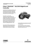
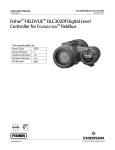
Quick Start Guide
DLC3020f Digital Level Controller
D103470X012
July 2012
Fisherr FIELDVUE™ DLC3020f Digital Level
Controller for FOUNDATION™ fieldbus
Contents
Installation . . . . . . . . . . . . . . . . . . . . . 3
Mounting . . . . . . . . . . . . . . . . . . . . . . 10
Electrical Connections . . . . . . . . . . . 14
Configuration . . . . . . . . . . . . . . . . . . 18
Calibration . . . . . . . . . . . . . . . . . . . . . 33
Nameplates and Schematics . . . . . . 37
Specifications . . . . . . . . . . . . . . . . . . 41
This quick start guide applies to:
Device Type
Device Revision
Hardware Revision
Firmware Revision
DD Revision
3020
1
1.0
1.0
0x03
Note
This quick start guide provides installation and initial setup and calibration information for the DLC3020f digital level controller
using AMS Suite: Intelligent Device Manager.
www.Fisher.com
DLC3020f Digital Level Controller
Quick Start Guide
D103470X012
July 2012
nInstallation Check List
Mounting
j
Instrument correctly configured and mounted on the sensor. See the appropriate
mounting procedure or installation instructions provided with the mounting kit.
Wiring and Electrical Connections
j
Conduit or I.S. barrier, if necessary, properly installed. Refer to local and national
electrical codes.
j Loop wiring properly connected to the LOOP + and - terminals in the terminal box.
Connect loop wiring as described on page 14.
2
Quick Start Guide
DLC3020f Digital Level Controller
D103470X012
July 2012
Installation
Do not install, operate, or maintain a DLC3020f digital level controller without being fully trained and qualified in field
instrument and accessory installation, operation, and maintenance. To avoid personal injury or property damage, it
is important to carefully read, understand, and follow all of the contents of this manual, including all safety
cautions and warnings. If you have any questions regarding these instructions contact your Emerson Process
Management sales office before proceeding.
Refer to figure 1 for the installation flow chart.
Figure 1. Installation Flowchart
START
Factory mounted
on 249 sensor
Yes
No
Install Heat
Insulator
Yes
High
temperature
application?
No
Mount DLC3020f
to Sensor
Make Electrical
Connections
Power Device
Proceed to
Set Up and Calibration
Configuration: On the Bench or in the Field
Configure the digital level controller before or after installation in the field.
It may be useful to configure the instrument on the bench before installation to ensure proper operation, and to
familiarize yourself with its functionality.
3
Quick Start Guide
DLC3020f Digital Level Controller
D103470X012
July 2012
Protecting the Coupling and Flexures
CAUTION
Damage to flexures and other parts can cause measurement errors. Observe the following steps before moving the sensor
and controller.
Lever Lock
The lever lock is built in to the coupling access door. When the door is open, it positions the lever in the neutral travel
position for coupling. In some cases, this function is used to protect the lever assembly from violent motion during
shipment.
A DLC3020f digital level controller will have one of the following mechanical configurations when received:
1. A fully assembled and coupled caged‐displacer system shipped with the displacer or driver rod blocked within the
operating range by mechanical means. In this case, the access handle (figure 2) will be in the unlocked position.
Remove the displacer blocking hardware before calibration (see the appropriate sensor instruction manual). The
coupling should be intact.
Figure 2. Sensor Connection Compartment (Adapter Ring Removed for Clarity)
MOUNTING STUDS
ACCESS HOLE
SHAFT CLAMP
1
SET SCREW
PRESS HERE TO
MOVE ACCESS HANDLE
NOTE:
1
SET SCREW IS USED TO LOCK THE LEVER IN PLACE FOR OPERATION
SLIDE ACCESS HANDLE TOWARD FRONT OF
UNIT TO EXPOSE ACCESS HOLE
CAUTION
When shipping an instrument mounted on a sensor, if the lever assembly is coupled to the linkage, and the linkage is
constrained by the displacer blocks, use of the lever lock may result in damage to bellows joints or flexure.
4
Quick Start Guide
DLC3020f Digital Level Controller
D103470X012
July 2012
2. If the displacer cannot be blocked because of cage configuration or other concerns, the transmitter is uncoupled
from the torque tube by loosening the coupling nut, and the access handle will be in the locked position. Before
placing such a configuration into service, couple the instrument to the sensor as follows:
a. Slide the access handle to the open position to lock the lever assembly in place and expose the access hole. Press
on the back of the handle as shown in figure 2 then slide the handle toward the front of the unit. Be sure the
locking handle drops into the detent.
b. If in process, ensure that the level or interface is in the lowest position on the displacer.
c. If on the bench, ensure that the displacer is dry and the displacer rod lever arm is not hitting a travel stop.
d. Insert a 10 mm deep well socket through the access hole and onto the torque tube shaft clamp nut. Tighten the
clamp nut to a maximum torque of 2.1 NSm (18 lbfSin).
e. Slide the access handle to the closed position. for operation or calibration. (Press on the back of the handle as
shown in figure 2 then slide the handle toward the rear of the unit.) Be sure the locking handle drops into the
detent.
5
Quick Start Guide
DLC3020f Digital Level Controller
D103470X012
July 2012
Hazardous Area Classifications and Special Instructions for “Safe Use” and
Installation in Hazardous Locations
Certain nameplates may carry more than one approval, and each approval may have unique installation/wiring
requirements and/or conditions of “safe use”. These special instructions for “safe use” are in addition to, and may
override, the standard installation procedures. Special instructions are listed by approval.
WARNING
Failure to follow these conditions of “safe use” could result in personal injury or property damage from fire or explosion,
and area re‐classification.
Note
This information supplements the nameplate markings affixed to the product.
Always refer to the nameplate itself to identify the appropriate certification. Contact your Emerson Process Management sales
office for approval/certification information not listed here.
CSA
Intrinsically Safe, Explosion‐proof, Division 2, Dust Ignition‐proof
No special conditions for safe use.
Refer to table 1 for approval information, figure 21 for the CSA schematic, and figure 23 for a typical CSA/FM
nameplate.
Table 1. Hazardous Area Classifications—CSA (Canada)
Certification Body
Certification Obtained
Entity Rating
Temperature Code
Enclosure Rating
Fieldbus
Intrinsically Safe
Class I, II, III Division 1 Groups A,B,C,
D,E,F,G T4 per drawing GE37118
CSA
RTD Terminals
Voc = 6.6 VDC
Isc = 29.5 mA
Po = 49 mW
Ca ≤ 22 μF
La ≤ 40 mH
Main Circuit Terminals
Vmax ≤ 24 VDC
Imax ≤ 380 mA
Pi ≤ 1.4 W
Ci = 5 nF
Li = 0 mH
FISCO
RTD Terminals
Voc = 6.6 VDC
Isc = 29.5 mA
Po = 49 mW
Ca ≤ 22 μF
La ≤ 40 mH
Main Circuit Terminals
Vmax ≤ 17.5 VDC
Imax ≤ 380 mA
Pi ≤ 5.32 W
Ci = 5 nF
Li = 0 mH
Explosion‐proof
Class I Division 1 Groups B,C,D T6
Class I Division 2 Groups A,B,C,D T6
Dust Ignition‐proof
Class II Division 1,2 Groups E,F,G T6
Class III
6
T4(Tamb ≤ 80_C)
Type 4X
T6(Tamb ≤ 80_C)
Type 4X
T6(Tamb ≤ 80_C)
Type 4X
---
Quick Start Guide
DLC3020f Digital Level Controller
D103470X012
July 2012
FM
Intrinsically Safe, Explosion‐proof, Non-Incendive, Dust Ignition‐proof
No special conditions for safe use.
Refer to table 2 for approval information, figure 24 for the FM schematic, and figure 23 for a typical CSA/FM
nameplate.
Table 2. Hazardous Area Classifications—FM (United States)
Certification Body
Certification Obtained
Entity Rating
Temperature Code
Enclosure Rating
Fieldbus
Intrinsically Safe
Class I, II, III Division 1 Groups A,B,C,
D,E,F,G T4 per drawing GE37117
FM
RTD Terminals
Voc = 6.6 VDC
Isc = 29.5 mA
Po = 49 mW
Ca ≤ 22 μF
La ≤ 40 mH
Main Circuit Terminals
Vmax ≤ 24 VDC
Imax ≤ 380 mA
Pi ≤ 1.4 W
Ci = 5 nF
Li = 0 mH
FISCO
RTD Terminals
Voc = 6.6 VDC
Isc = 29.5 mA
Po = 49 mW
Ca ≤ 22 μF
La ≤ 40 mH
Main Circuit Terminals
Vmax ≤ 17.5 VDC
Imax ≤ 380 mA
Pi ≤ 5.32 W
Ci = 5 nF
Li = 0 mH
Explosion‐proof
Class I Division 1 Groups A,B,C,D T5
Non‐Incendive
Class I,II,III Division 2 Groups A,B,C,D,
E,F,G T4
Dust Ignition‐proof
Class II Division 1 Groups E,F,G T5
−−−
T4(Tamb ≤ 80_C)
NEMA 4X, IP66
T5(Tamb ≤ 80_C)
NEMA 4X, IP66
T4(Tamb ≤ 80_C)
NEMA 4X, IP66
T5(Tamb ≤ 80_C)
NEMA 4X, IP66
7
Quick Start Guide
DLC3020f Digital Level Controller
D103470X012
July 2012
ATEX
Special Conditions for Safe Use
Intrinsically Safe & Dust
This apparatus can only be connected to an intrinsically safe certified equipment and this combination must be
compatible regarding the intrinsic safety rules (see electrical parameters in table 3).
Flameproof & Dust, Type n & Dust
No special conditions for safe use.
Refer to table 3 for additional approval information and figure 26 for a typical ATEX/IECEx nameplate.
Table 3. Hazardous Area Classifications—ATEX
Certification
Certification Obtained
Entity Rating
Temperature Code
Enclosure Rating
Fieldbus
II 1 G & D
Intrinsically Safe
Ex ia IIC T5/T6 Ga
Dust
Ex iaD 20 IP66 T87_C (Tamb ≤ 80_C) Da
Ex iaD 20 IP66 T80_C (Tamb ≤ 73_C) Da
ATEX
II 2 G & D
Flameproof
Ex d IIC T5/T6
Dust
Ex tD A21 IP66 T87_C (Tamb ≤ 80_C)
Ex tD A21 IP66 T80_C (Tamb ≤ 73_C)
II 3 G & D
Type n
Ex nA IIC T5/T6
Dust
Ex tD A22 IP66 T87_C (Tamb ≤ 80_C)
Ex tD A22 IP66 T80_C (Tamb ≤ 73_C)
8
Ui ≤ 24 V
Ii ≤ 380 mA
Pi ≤ 1.4 W
Ci + 5 nF
Li + 0 mH
FISCO
T5(Tamb ≤ 80_C)
T6(Tamb ≤ 73_C)
IP66
T5(Tamb ≤ 80_C)
T6(Tamb ≤ 73_C)
IP66
T5(Tamb ≤ 80_C)
T6(Tamb ≤ 73_C)
IP66
Ui ≤ 17.5 V
Ii ≤ 380 mA
Pi ≤ 5.32 W
Ci + 5 nF
Li + 0 mH
---
Quick Start Guide
DLC3020f Digital Level Controller
D103470X012
July 2012
IECEx
Conditions of Certification
Intrinsically Safe & Dust
This apparatus shall only be connected to an intrinsically safe certified equipment and this combination must be
compatible regarding the intrinsic safety rules (see electrical parameters in table 4).
Flameproof & Dust, Type n & Dust
No conditions of certification.
Refer to table 4 for additional approval information, and figure 26 for a typical ATEX/IECEx nameplate.
Table 4. Hazardous Area Classifications—IECEx
Certification
Certification Obtained
Entity Rating
Temperature Code
Enclosure Rating
Fieldbus
Intrinsically Safe
Ex ia IIC T5/T6 Ga
Dust
Ex iaD 20 IP66 T87_C (Tamb ≤ 80_C) Da
Ex iaD 20 IP66 T80_C (Tamb ≤ 73_C) Da
IECEx
Flameproof
Ex d IIC T5/T6
Dust
Ex tD A21 IP66 T87_C (Tamb ≤ 80_C)
Ex tD A21 IP66 T80_C (Tamb ≤ 73_C)
Type n
Ex nA IIC T5/T6
Dust
Ex tD A22 IP66 T87_C (Tamb ≤ 80_C)
Ex tD A22 IP66 T80_C (Tamb ≤ 73_C)
Ui ≤ 24 V
Ii ≤ 380 mA
Pi ≤ 1.4 W
Ci + 5 nF
Li + 0 mH
FISCO
T5(Tamb ≤ 80_C)
T6(Tamb ≤ 73_C)
IP66
T5(Tamb ≤ 80_C)
T6(Tamb ≤ 73_C)
IP66
T5(Tamb ≤ 80_C)
T6(Tamb ≤ 73_C)
IP66
Ui ≤ 17.5 V
Ii ≤ 380 mA
Pi ≤ 5.32 W
Ci + 5 nF
Li + 0 mH
---
9
Quick Start Guide
DLC3020f Digital Level Controller
D103470X012
July 2012
Mounting
WARNING
To avoid personal injury or property damage, always wear protective gloves, clothing, and eyewear when performing any
installation operations.
Personal injury or property damage due to sudden release of pressure, contact with hazardous fluid, fire, or explosion can
be caused by puncturing, heating, or repairing a displacer that is retaining process pressure or fluid. This danger may not
be readily apparent when disassembling the sensor or removing the displacer. Before disassembling the sensor or
removing the displacer, observe the appropriate warnings provided in the sensor instruction manual.
Check with your process or safety engineer for any additional measures that must be taken to protect against process
media.
Mounting the 249 Sensor
The 249 sensor is mounted using one of two methods, depending on the specific type of sensor. If the sensor has a
caged displacer, it typically mounts on the side of the vessel as shown in the left image in figure 3. If the sensor has a
cageless displacer, the sensor mounts on the side or top of the vessel as shown in the right image in figure 3.
Figure 3. Typical Mounting
A3788‐1
A3789‐1
TYPICAL CAGED SENSOR MOUNTING
10
TYPICAL CAGELESS SENSOR MOUNTING
Quick Start Guide
DLC3020f Digital Level Controller
D103470X012
July 2012
The DLC3020f digital level controller is typically shipped attached to the sensor. If ordered separately, it may be
convenient to mount the digital level controller to the sensor and perform the initial setup and calibration before
installing the sensor on the vessel.
Note
Caged sensors have a rod and block installed on each end of the displacer to protect the displacer in shipping. Remove these parts
before installing the sensor to allow the displacer to function properly.
DLC3020f Orientation
Mount the DLC3020f with the torque tube shaft clamp access hole (see figure 2) pointing downward to allow
accumulated moisture drainage.
Note
If alternate drainage is provided by the user, and a small performance loss is acceptable, the instrument could be mounted in 90
degree rotational increments around the pilot shaft axis. The LCD meter may be rotated in 90 degree increments to accommodate
this.
The digital level controller and torque tube arm are attached to the sensor either to the left or right of the displacer, as
shown in figure 4. This can be changed in the field on the 249 sensors (refer to the appropriate sensor instruction
manual). Changing the mounting also changes the effective action, because the torque tube rotation for increasing
level, (looking at the protruding shaft), is clockwise when the unit is mounted to the right of the displacer and counter‐
clockwise when the unit is mounted to the left of the displacer.
All 249 caged sensors have a rotatable head. That is, the digital level controller can be positioned at any of eight
alternate positions around the cage as indicated by the position numbers 1 through 8 in figure 4. To rotate the head,
remove the head flange bolts and nuts and position the head as desired.
Mounting the DLC3020f on a 249 Sensor
Refer to figure 2 unless otherwise indicated.
1. If the set screw in the access handle (figure 5) is driven against the spring plate, back it out until the head is flush
with the outer surface of the handle, using a 2 mm hex key. Slide the access handle to the open position to lock the
lever assembly in place and to expose the access hole. Press on the back of the handle as shown in figure 2 then
slide the handle toward the front of the unit. Be sure the locking handle drops into the detent.
2. Using a 10 mm deep well socket inserted through the access hole, loosen the shaft clamp (figure 2).
3. Remove the hex nuts from the mounting studs. Do not remove the adapter ring.
CAUTION
Measurement errors can occur if the torque tube assembly is bent or misaligned during installation.
11
Quick Start Guide
DLC3020f Digital Level Controller
D103470X012
July 2012
Figure 4. Typical Mounting Positions for the FIELDVUE DLC3020f Digital Level Controller on a Fisher 249 Sensor
SENSOR
LEFT‐OF‐DISPLACER
1
5
7
6
RIGHT‐OF‐DISPLACER
8
1
3
CAGED
3
1
5
4
2
1
4
2
8
7
6
CAGELESS
249VS
1
249W
249W
249VS
NOT AVAILABLE FOR SIZE NPS 2 CL300 AND CL600 249C SENSOR.
Figure 5. Close‐up of Set‐Screw
SET‐SCREW (2mm)
4. Position the digital level controller so the access hole is on the bottom of the instrument.
5. Carefully slide the mounting studs into the sensor mounting holes until the digital level controller is snug against
the sensor mounting flange.
6. Reinstall the hex nuts on the mounting studs and tighten the hex nuts to 10 NSm (88.5 lbfSin).
Mounting the DLC3020f for High Temperature Applications
Refer to figure 7 for parts identification except where otherwise indicated.
The digital level controller requires an insulator assembly when temperatures exceed the limits shown in figure 6.
A torque tube shaft extension is required for a 249 sensor when using an insulator assembly.
12
Quick Start Guide
DLC3020f Digital Level Controller
D103470X012
July 2012
PROCESS TEMPERATURE (_F)
AMBIENT TEMPERATURE (_C)
-40
800
-30 -20
-10
0
10
20
30
40
50
60
80
TOO
HOT
HEAT INSULATOR
REQUIRED
400
70
425
400
300
200
100
-325
-40
0
NO HEAT INSULATOR NECESSARY
0
1
-100
TOO
COLD
-20
HEAT INSULATOR
REQUIRED
0
20
40
60
-200
80
100 120
140
160 176
PROCESS TEMPERATURE (_C)
Figure 6. Guidelines for Use of Optional Heat Insulator Assembly
AMBIENT TEMPERATURE (_F)
STANDARD TRANSMITTER
NOTES:
1
FOR
PROCESS TEMPERATURES BELOW -29_C (-20_F) AND ABOVE 204_C (400_F) SENSOR MATERIALS
MUST BE APPROPRIATE FOR THE PROCESS - SEE TABLE 9.
2. IF AMBIENT DEW POINT IS ABOVE PROCESS TEMPERATURE, ICE FORMATION MIGHT CAUSE INSTRUMENT
MALFUNCTION AND REDUCE INSULATOR EFFECTIVENESS.
39A4070‐B
A5494‐1
CAUTION
Measurement errors can occur if the torque tube assembly is bent or misaligned during installation.
1. When mounting a DLC3020f on a 249 sensor, secure the shaft extension to the sensor torque tube shaft via the
shaft coupling and set screws, with the coupling centered as shown in figure 7.
2. Slide the access handle to the locked position to expose the access hole. Press on the back of the handle as shown in
figure 2 then slide the handle toward the front of the unit. Be sure the locking handle drops into the detent.
Figure 7. Digital Level Controller Mounting on Sensor in High Temperature Applications
INSULATOR
(KEY 57)
SHAFT
EXTENSION
(KEY 58)
SET SCREWS
(KEY 60)
SHAFT
COUPLING
(KEY 59)
WASHER
(KEY 78)
HEX NUTS
(KEY 34)
CAP SCREWS
(KEY 63)
MN28800
20A7423‐C
B2707
SENSOR
MOUNTING STUDS
(KEY 33)
DIGITAL LEVEL CONTROLLER
3. Remove the hex nuts from the mounting studs.
4. Position the insulator on the digital level controller, sliding the insulator straight over the mounting studs.
5. Install 4 washers (key 78) over the studs. Install the four hex nuts and tighten.
13
DLC3020f Digital Level Controller
July 2012
Quick Start Guide
D103470X012
6. Carefully slide the digital level controller with the attached insulator over the shaft coupling so that the access hole
is on the bottom of the digital level controller.
7. Secure the digital level controller and insulator to the torque tube arm with four cap screws.
8. Tighten the cap screws to 10 NSm (88.5 lbfSin).
Electrical Connections
The following describes how to make fieldbus connections to the digital level controller.
WARNING
To avoid personal injury resulting from electrical shock, do not exceed the maximum input voltage specified in table 8 or on
the product nameplate. If the input voltage specified differs, do not exceed the lowest specified maximum input voltage.
WARNING
Select wiring and/or cable glands that are rated for the environment of use (such as hazardous area, ingress protection and
temperature). Failure to use properly rated wiring and/or cable glands can result in personal injury or property damage
from fire or explosion
Wiring connections must be in accordance with local, regional, and national codes for any given hazardous area approval.
Failure to follow the local, regional, and national codes could result in personal injury or property damage from fire or
explosion.
Personal injury or property damage caused by fire or explosion may occur if this connection is attempted in a potentially
explosive atmosphere or in an area that has been classified as hazardous. Confirm that area classification and atmosphere
conditions permit the safe removal of the terminal box cover before proceeding
Fieldbus Connections
The digital level controller is normally powered over the bus from a fieldbus 9 to 32 volt power supply and can be
connected to the segment using field wiring. Refer to the site preparation guide for proper wire types, termination,
length, etc. for a fieldbus segment.
Note
As shipped from the factory, the DLC3020f will have the transducer block mode set Out of Service. See the Configuration section
for information on setup and calibration and placing the instrument in service. The initial value for all blocks are shown in the
parameter list for each block in the Blocks section.
14
Quick Start Guide
DLC3020f Digital Level Controller
D103470X012
July 2012
1. Remove the terminal box cover (key 6) from the terminal box (key 5).
2. Bring the field wiring into the terminal box. When applicable, install conduit using local and national electrical codes
which apply to the application.
3. Connect one wire from the control system output card to the LOOP + terminal in the terminal box as shown in
figure 8. Connect the other wire from the control system output card to the LOOP - terminal. The instrument is not
polarity sensitive.
WARNING
Personal injury or property damage, caused by fire or explosion, can result from the discharge of static electricity. Connect
a 14 AWG (2.08 mm2) ground strap between the digital level controller and earth ground when flammable or hazardous
gases are present. Refer to national and local codes and standards for grounding requirements.
4. As shown in figure 8, ground terminals are available for connecting a safety ground, earth ground, or drain wire. The
safety ground terminal is electrically identical to the earth ground. Make connections to these terminals following
national and local codes and plant standards.
5. Replace and tighten the terminal box cover, ensuring that it is weather‐tight; engage the optional set screw lock if
required.
Figure 8. Terminal Box Assembly
CLIP‐ON +
CLIP‐ON -
RTD
SIMULATE ENABLE
SAFETY GROUND
LOOP+
LOOP-
15
DLC3020f Digital Level Controller
July 2012
Quick Start Guide
D103470X012
Communication Connections
WARNING
Personal injury or property damage caused by fire or explosion may occur if this connection is attempted in a potentially
explosive atmosphere or in an area that has been classified as hazardous. Confirm that area classification and atmosphere
conditions permit the safe removal of the terminal box cap before proceeding.
Note
Host system device manager interfaces, such as Emerson's AMS Device Manager or the Field Communicator communicate directly
with the device.
A FOUNDATION fieldbus communicating device, such as a Field Communicator, interfaces with the DLC3020f from any
wiring termination point in the segment. If you choose to connect the fieldbus communicating device directly to the
instrument, attach the device to the LOOP + / - clip‐on connections inside the terminal box to provide local
communications with the instrument.
16
Quick Start Guide
DLC3020f Digital Level Controller
D103470X012
July 2012
nConfiguration and Calibration Check List
j
Configuration and Calibration complete.
j
Configuration check. Confirm all final process data is correctly entered.
j
j
Transmitter correctly reports PV.
Ensure Setup Calibration log is saved.
Transmitter is ready to be placed on line.
Accessing Configuration and Calibration Procedures
Navigation paths for Configuration and Calibration procedures are included for both AMS Device Manager and the
Field Communicator.
For example, to access Guided Calibrations:
AMS Device Manager
Configure > Calibrate > Guided Calibrations
Field Communicator
Configure > Calibrate > Full Calibration (Bench) or Full Calibration (Field)
Menu selections are shown in italics, e.g., Full Calibration (Field).
17
DLC3020f Digital Level Controller
Quick Start Guide
D103470X012
July 2012
Configuration
Note
This quick start guide documents procedures in AMS Device Manager 10.5 and later. Earlier versions of AMS Device Manager
contain the same procedures and methods, but access is through the block in which they reside.
Note
The primary transducer block must be set to out of service before the device can be configured.
When using AMS Device Manager 10.1 and earlier go to Target Mode in Block Modes tab to set the primary transducer block in and
out of service. Refer to figure 9.
Figure 9. Block Modes Tab (AMS Device Manager 10.1 and earlier)
BLOCK MODES
SET THE TARGET
MODE TO OUT
OF SERVICE
CONFIGURE
Guided Setup
AMS Device Manager
Configure > Guided Setup
Field Communicator
Configure > Instrument Setup
Access Instrument Setup from the Guided Setup tab, as shown in figure 10, for sensor, device and process fluid setup.
Follow the prompts to setup the DLC3020f.
18
Quick Start Guide
DLC3020f Digital Level Controller
D103470X012
July 2012
Figure 10. Guided Setup
GUIDED SETUP
INSTRUMENT SETUP
CONFIGURE
Manual Setup
AMS Device Manager
Configure > Manual Setup
Field Communicator
Configure > Manual Setup
The Device, Process Fluid, Instrument Display, Snap Acting Control, and Options tabs are accessible through Manual Setup.
Note
An error will be generated if the instrument is put back in service without applying device configuration changes; you must apply
changes before putting the instrument back In Service. To clear an error, set the Mode to Out of Service, select Apply, then put
back In Service.
Device
Select the Device tab (figure 11) to access Variable Configuration, Sensor Limits, Sensor Hardware Information, Sensor
Units, Mode, Sensor Parameters, Instrument Mount Position, and Torque Tube.
Variable Configuration
Type of Measurement— Level or Interface
Primary Value Range High— defines the maximum operational end point for reported PV.
Primary Value Range Low— defines the minimum operational end point for reported PV. Default is above zero.
19
Quick Start Guide
DLC3020f Digital Level Controller
D103470X012
July 2012
Figure 11. Configure > Manual Setup > Device
DEVICE TAB
VARIABLE
CONFIGURATION
SELECT UNIT SYSTEM
SENSOR PARAMETERS
MANUAL SETUP
SENSOR LIMITS
CONFIGURE
SENSOR HARDWARE
INFORMATION
TORQUE TUBE
INSTRUMENT
MOUNT POSITION
Primary Value Offset— the constant offset applied to the level/interface measurement.
Primary Value Range Units— units for PV, PV Range, and Sensor Limits.
Sensor Limits
Upper Sensor Limit— Indicates the maximum usable value for the Primary Value Range High.
Lower Sensor Limit— Indicates the minimum usable value for the Primary Value Range Low.
The Upper and Lower Sensor Limit limit what the DLC3020f can read; values above and below these limits will not be
detected by the instrument. This is a dynamic reading based on temperature used when Temperature Compensation
is enabled.
Sensor Hardware Information
Enter the following information by selecting Sensor Hardware Information.
Model Type, End Connection Style, End Connection Type, Body Material, Pressure Rating, Mechanical Sensor Serial
Number, Displacer Size Displacer Material, Displacer Rating, G Dimension, Torque Tube Material, Torque Tube Wall,
Heat Insulator.
Sensor information is typically found on the sensor nameplate, as shown in figure 12.
Note
This data is informational only and is not used in calibration or PV calculations.
20
Quick Start Guide
DLC3020f Digital Level Controller
D103470X012
July 2012
Sensor Units
Select the appropriate sensor units for your application.
Note
Default units from factory are SI (Metric).
If you choose Mixed Units you must select the units for each sensor parameter.
Figure 12. Typical Sensor Nameplate
SENSOR TYPE
DISPLACER
PRESSURE RATING
ASSEMBLY
PRESSURE RATING
DISPLACER
WEIGHT
76543210
249B
PSI
285/100 F
1500 PSI
2 x 32 INCHES
WCB STL
103 CU‐IN
4 3/4 LBS
MONEL
316 SST
K MONEL/STD
DISPLACER
MATERIAL
DISPLACER
VOLUME
23A1725‐E sht 1
E0366
ASSEMBLY MATERIAL
TRIM MATERIAL
TORQUE TUBE MATERIAL
DISPLACER SIZE
(DIAMETER X LENGTH)
Unit System—English Units, Metric/SI Units, Mixed Units
Length Units—mm, cm, m, in, or ft
Volume Units—mm3, ml, L, in3
Weight Units—oz, lb, g, or kg
Temperature Units—_F, _R, _C, or K
Torque Rate Units—NSm/deg, dyneScm/deg, lbfSin/deg
Fluid Density Units—degAPI, SGU (Specific Gravity) lb/in3, lb/ft3, lb/gal, degBaum hv, degBaum lt, kg/m3, g/cm3, kg/L,
g/ml, or g/L
Sensor Parameters
Enter the sensor parameters. Selections shown in the drop down are based on the sensor units chosen.
Displacer Length
Displacer Volume
Displacer Weight
Driver Rod Length
Instrument Mount Position
21
Quick Start Guide
DLC3020f Digital Level Controller
D103470X012
July 2012
Note
Table 5 provides the driver rod length of 249 sensors with vertical displacers. If your sensor isn't included in table 5 refer to figure 13
to determine the driver rod length.
Table 5. Driver Rod Length(1)
Driver Rod
Sensor Type(2)
mm
Inch
249
203
8.01
249B
203
8.01
249BF(3)
203
8.01
249BP
203
8.01
249C
169
6.64
249CP
169
6.64
249K
267
10.5
249L
229
9.01
249N
267
10.5
249P(3)
(CL125-CL600)
203
8.01
249P(3)
(CL900-CL2500)
229
9.01
249V (Special)(1)(3)
See serial card
See serial card
249V (Std)(3)
343
13.5
249VS
343
13.5
249W
203
8.01
1. Driver rod length is the perpendicular distance between the vertical centerline of the displacer and the horizontal centerline of the torque tube. See figure 13. If you cannot determine the
driver rod length, contact your Emerson Process Management sales office and provide the serial number of the sensor.
2. This table applies to sensors with vertical displacers only. For sensor types not listed, or sensors with horizontal displacers, contact your Emerson Process Management sales office for the
driver rod length. For other manufacturers' sensors, see the installation instructions for that mounting.
3. 249BF, 249P, and 249V sensors are only available in Europe.
22
Quick Start Guide
DLC3020f Digital Level Controller
D103470X012
July 2012
Figure 13. Method of Determining Driver Rod Length from External Measurements
VERTICAL CL
OF DISPLACER
VESSEL
HORIZONTAL CL
OF TORQUE TUBE
DISPLACER ROD LENGTH
Torque Tube
Torque Tube Material—select the material of the torque tube being used. See the sensor nameplate.
View Torque Tube Table—select View Torque Tube Table to see the torque tube gain over the entire temperature range
and the compensated torque rate.
23
Quick Start Guide
DLC3020f Digital Level Controller
D103470X012
July 2012
Process Fluid
Select the Process Fluid tab (figure 14) to access Process Fluid, Temperature Compensation, and Mode.
Figure 14. Configure > Manual Setup > Process Fluid
MANUAL SETUP
CONFIGURE
PROCESS FLUID TAB
PROCESS FLUID
CHANGE
PROCESS FLUID
TEMPERATURE
COMPENSATION
MODE
VIEW DENSITY PARAMETERS
Note
The instrument software contains density tables for common categories of fluids. Custom tables can be built if needed.
Some fluid categories have wide variations within fluid types. Select the fluid category and then the fluid type.
Input the operating process temperature and the density. The DLC3020f will load the density table that best matches the fluid type
at operating conditions.
Process Fluid
Fluid Name
Density In Use
Change Process Fluid —Select Change Process Fluid to begin the process to properly select the corrections for density
of the fluid that occur at operational temperature.
If Temperature Compensation is selected, the proper density table for use in temperature compensation is selected. If
Temperature Compensation is not needed, enter the operating conditions and name the fluid.
24
Quick Start Guide
DLC3020f Digital Level Controller
D103470X012
July 2012
Temperature Compensation
If Temperature Compensation is selected, provide the following information:
Temperature Input—select None, Manual, AO Block, or RTD.
Temperature compensation, when enabled, can come from a manually entered temperature, a temperature from a
fieldbus transmitter (AO block) or a temperature from an RTD.
Temperature for Compensation—the temperature in use for fluid density and torque tube material compensation.
View Fluid Density Table
Select View Fluid Density Table to see information concerning the temperature effect on process fluid density.
Instrument Display
Select the Instrument Display tab (figure 15) to access Display Option, Device Display Primary Value Units, Decimal Places,
Display Primary Value Offset, and Scrolling Message Control.
Figure 15. Configure > Manual Setup > Instrument Display
MANUAL
SETUP
INSTRUMENT
DISPLAY TAB
SCROLLING
MESSAGE CONTROL
MODE
DISPLAY OPTION
DEVICE DISPLAY PRIMARY
VALUE UNITS
DECIMAL PLACES
DISPLAY PRIMARY VALUE OFFSET
CONFIGURE
Display Option
Select Primary Value Only, % Range, or Primary Value / % Range to be displayed on the DLC3020f LCD.
Device Display Primary Value Units
Select the units for the device display Primary Value.
25
Quick Start Guide
DLC3020f Digital Level Controller
D103470X012
July 2012
Decimal Places
Enter the number of desired decimal places for the device display.
Display Primary Value Offset
Enter the PV Offset to apply it to the LCD readout.
Scrolling Message Control
Messages that can be scrolled on the LCD screen. Choose from; Primary Value Bad, Primary Value Uncertain, Failed
Alert, Maintenance Alert, or Advisory Alert.
Snap Acting Control
Select the Snap Acting Control tab (figure 16) to access Snap Acting Control, Primary Value, Primary Value Percent, DI1
Trip Point Settings, DI2 Trip Point Settings, and Mode.
Figure 16. Configure > Manual Setup > Snap Acting Control
SNAP ACTING CONTROL
SNAP ACTING
CONTROL TAB
DI1 TRIP POINT SETTINGS
MODE
MANUAL
SETUP
PRIMARY VALUE
PRIMARY VALUE
PERCENT
DI2 TRIP POINT
SETTINGS
CONFIGURE
Snap Acting Control
The DLC3020f can act as a snap acting controller while simultaneously reporting PV. When Snap Acting Control is
enabled, either one or both of the DI blocks will act as controllers and output a 0 (inactive) or 1 (active), depending on
if the level has gone past (either rising or falling) a user specified level value.
Snap Acting Control—enable or disable Snap Acting Control.
Snap Units—select the desired snap unit in engineering units; length units or percent (%).
26
Quick Start Guide
DLC3020f Digital Level Controller
D103470X012
July 2012
Primary Value
PV in engineering units
Primary Value Percent
PV in %
DI1 Trip Point Settings
Set Channel 1 or 2 of the DI for snap acting control.
DI1 Action—indicate whether the trip point is active on rising or falling level.
DI1 Trip Point—enter the point where DI1 is active.
DI1 Deadband—enter the desired deadband. This is the distance away from the trip point that DI1 clears.
DI1 Readback—indicates the status of the trip point.
0 indicates that DI1 Trip is inactive. 1 indicates DI1 Trip is active.
DI2 Trip Point Settings
DI2 Action—indicate whether the trip point is active on rising or falling level.
DI2 Trip Point—enter the point where DI2 is active.
DI2 Deadband—enter the desired deadband. This is the distance away from the trip point that DI2 clears.
DI2 Readback—indicates the status of the trip point.
0 indicates that DI2 Trip is inactive. 1 indicates DI2 Trip is active.
Options
Select the Options tab (figure 17) to access Write Alarm, Block Alarm, Write Lock, Confirm Time, Communication Timeout,
Function Block Available, Features Selected, Alert Key, Maximum Alerts Allowed, Maximum Alerts Possible, Resource Block,
Transducer Block, and Mode.
Write Alarm
The Write Alarm (WRITE_ALM [40]) is used to alert when parameters are writable to the device.
Write Alarm Disabled—select to disable the Write Alarm
27
Quick Start Guide
DLC3020f Digital Level Controller
D103470X012
July 2012
Figure 17. Configure > Manual Setup > Options
WRITE ALARM
MANUAL SETUP
COMMUNICATION TIMEOUT
CONFIRM TIME
OPTIONS TAB
MODE
FUNCTION
BLOCK AVAILABLE
ALERT KEY
MAXIMUM ALERTS ALLOWED
MAXIMUM ALERTS POSSIBLE
BOCK ALARM
RESOURCE BLOCK
TRANSDUCER BLOCK
CONFIGURE
WRITE LOCK
FEATURES SELECTED
Alarm State—indicates the state of the Write Alarm. Five states are possible; Undefined, Clear‐Reported, Clear-Not
Reported, Active‐Reported, Active‐Not Reported.
Unacknowledged—select Undefined, Acknowledged, or Unacknowledged
Block Alarm
The block alarm is used for all configuration, hardware, connection failure, or system problems in the block. Alarm
Summary (ALARM_SUM [37]) determines if the Write Alarm and Block Alarm are disabled.
Block Alarm Disabled—select to disable the Block Alarm
Alarm State—indicates the state of the Block Alarm. Five states are possible; Undefined, Clear‐Reported, Clear-Not
Reported, Active‐Reported, Active‐Not Reported.
Unacknowledged—select Undefined, Acknowledged, or Unacknowledged
Write Lock
Write Lock determines if writes are permissible to other device parameters.
Write Lock— When Write Lock is set to Locked, no writes are permitted to any parameters within the device except to
set Write Lock to Not Locked. When locked, the device functions normally, updating inputs and outputs and executing
algorithms. When Write Lock is set to Not Locked, the Write Alarm alert is active.
Write Priority—Write Priority sets the priority for Write Alarm. The lowest priority is 0. The highest is 15.
28
Quick Start Guide
D103470X012
DLC3020f Digital Level Controller
July 2012
Confirm Time
Confirm Time determines the time in 1/32 of a millisecond, the instrument waits for confirmation of receipt of a report
before trying again. If Confirm Time is 0, the instrument does not try to resend the report. Enter 0 or a value between
320000 (10 seconds) and 640000 (20 seconds).
Communication Timeout
Rcas Time‐Out—Rcas Timeout determines how long function blocks in the DLC3020f should wait before giving up on
remote computer writes to RCas parameters. When the timeout is exceeded, the block sheds to the next mode as
defined by the block shed options. If RCas Timeout is set to 0, the block will not shed from RCas. Enter a positive value
in the RCas Timeout Timeout field. Time duration is in 1/32 milliseconds (640000 = 20 secs).
Note
Typically this parameter does not need to be changed. The unit will be operational using the default values assigned by the factory.
Perform this procedure only if a remote computer is sending setpoints from your “advanced” control.
Default value for RCas Timeout is 20 seconds.
Rout Time-Out—ROut Timeout (SHED_ROUT [27]) determine how long function blocks in the DLC3020f should wait
before giving up on computer writes to ROut parameters. When the timeout is exceeded, the block sheds to the next
mode as defined by the block shed options. If ROut Timeout is set to 0, the block will not shed from ROut. Enter a
positive value in the ROut Timeout field. Time duration is in 1/32 milliseconds (640000 = 20 secs).
Note
Typically this parameter does not need to be changed. The unit will be operational using the default values assigned by the factory.
Perform this procedure only if a remote computer is sending setpoints from your “advanced” control.
Default value for ROut Timeout is 20 seconds.
Write Lock—permits using Write Lock to prevent any external change to parameter values. Block connections and
calculation results will proceed normally, but the configuration is locked.
Reannunciation—permits the instrument to support Reannunciation of alarms.
Function Block Available
CasIn to Transducer Block
29
DLC3020f Digital Level Controller
Quick Start Guide
D103470X012
July 2012
Features Selected
Note
Typically this parameter does not need to be changed. The unit will be operational using the default values assigned by the factory.
Features Selected indicates which Resource Block Options features have been selected and is used to select the
desired features.
Reports—Selecting reports enables alert and event reporting. Reporting of specific alerts may be suppressed.
Fault State—Selecting Fault State enables the ability of the output block to react to various abnormal conditions by
shedding mode.
Write Lock—When selected, permits using Write Lock to prevent any external change to parameter values. Block
connections and calculation results will proceed normally, but the configuration is locked.
Reannunciation— When selected, the instrument will support Reannunciation of alarms.
Alert Key
Alert Key is a number that permits grouping alerts. This number may be used to indicate to the operator the source of
the alert, such as the instrument, plant unit, etc. Enter a value between 1 and 255.
Maximum Alerts Allowed
The number of alert reports that the device can send without getting a confirmation up to the maximum permitted
Resource Block
Tag Description— The Tag Description is used to assign a unique 32 character description to each block within the
digital level controller to describe the intended application of the block.
Strategy— Strategy permits strategic grouping of blocks so the operator can identify where the block is located. The
blocks may be grouped by plant area, plant equipment, etc. Enter a value between 0 and 65535 in the Strategy field.
Transducer Block
Tag Description— The Tag Description is a 32 character description used to assign a unique description to each block
within the digital level controller to describe the intended application for the block.
Strategy— Strategy permits strategic grouping of blocks so the operator can identify where the block is located. The
blocks may be grouped by plant area, plant equipment, etc. Enter a value between 0 and 65535 in the Strategy field.
Alert Setup
AMS Device Manager
Configure > Alert Setup
Field Communicator
Configure > Alert Setup
The Alert Setup tab is shown in figure 18.
30
Quick Start Guide
DLC3020f Digital Level Controller
D103470X012
July 2012
Figure 18. Alert Setup
ALERT SETUP
ALERT SETUP TAB
ELECTRONICS
OPERATIONAL
RATE LIMIT
SCROLL DOWN TO VIEW:
SENSOR BOARD
TEMPERATURE LIMIT
INPUT COMPENSATION ERROR
CONFIGURE
Alerts
The DLC3020f provides two levels of alerts; Instrument alerts and PlantWeb alerts.
Instrument Alert Conditions
Instrument Alert Conditions, when enabled, detect many operational and performance issues that may be of interest.
To view these alerts, the user must open the appropriate status screen on a host such as AMS Device Manager or a
Field Communicator.
PlantWeb Alerts
Instrument alert conditions can be used to trigger PlantWeb alerts that will be reported in Failed, Maintenance or
Advisory categories, as configured by the user. PlantWeb alerts, when enabled, can participate in the DeltaV alarm
interface tools such as the alarm banner, alarm list and alarm summary.
When a PlantWeb alert occurs, the DLC3020f sends an event notification and waits a specified period of time for an
acknowledgment to be received. This occurs even if the condition that caused the alert no longer exists. If the
acknowledgment is not received within the pre‐specified time‐out period, the event notification is retransmitted. This
reduces the possibility of alert messages getting lost.
DLC3020f alerts can be reported in the following categories.
Failed— indicates a problem with the DLC3020f that affects its operation. Immediate action is required for a Failed
condition.
31
DLC3020f Digital Level Controller
Quick Start Guide
July 2012
D103470X012
Maintenance— indicates a problem with the DLC3020f that, if ignored, could eventually lead to its failure. Maintenance
conditions require prompt action.
Advisory— indicates a minor problem with the DLC3020f. An advisory condition does not have an impact on the
process or device.
No Category— the alert has not been categorized.
Suppress PlantWeb Alert— the alert is still evaluated by the DLC3020f, but, it does not report the status condition
through an instrument alert.
Electronics
D Pending Memory Fail— when selected indicates if a pending memory error has been detected in the main board.
D Static Memory Fail— when selected indicates if a memory error has been detected in the main board.
Operational
D PV Exceeds Sensor Range— when selected indicates if the Primary Variable (PV) has reached or exceeded the Sensor
Range and is no longer correct.
D PV Range Exceeds Sensor Range— when selected indicates if the Primary Variable (PV) Range has exceeded the
range of the sensor's current calibration. The PV is still accurate but could move out of sensor range.
D PV Exceeds Primary Range— when selected indicates if the the Primary Variable (PV) has exceeded the PV Range.
D Calibration Validity— when selected indicates if a vital calibration parameter has been changed.
Rate Limit
D Displacer Rise Rate Exceeded— when selected indicates if the device detected a rise rate that exceeded the Rapid
Rate Limit.
D Displacer Fall Rate Exceeded Alert— when selected indicates if the device detected a fall rate that exceeded the
Rapid Rate Limit.
D Rapid Rate Limit—when selected, triggers an alarm when the configured set point has been exceeded. Rapid rate
limit is user‐configured based on application.
Select Clear Rate Limit Alert to clear the alert
RTD Sensor
D RTD Sensor—when selected indicates if the RTD readings are out of range or the RTD is incorrectly connected.
D RTD Open—when selected indicates if the RTD is not connected.
Sensor Board
D Instrument Temperature Sensor— when selected indicates if the electronic sensor readings are out of range.
D Sensor Board Processor— when selected indicates if the device cannot communicate properly or other electronic
problem is effecting the processor.
32
Quick Start Guide
DLC3020f Digital Level Controller
D103470X012
July 2012
D Hall Sensor— when selected indicates if the Hall Sensor readings are out of range.
Temperature Limit
D Instrument Temperature High— when selected indicates if the device has exceeded the Instrument Temperature
High Limit.
D Instrument Temperature Low— when selected indicates if the device has exceeded the Instrument Temperature
Low Limit.
Input Compensation Error
D Temperature Input Error— when selected indicates if the AO temperature status or RTD status has become “Bad" or
“Uncertain" or the device is not set up correctly to receive AO temperature.
D Upper Fluid Input Error— when selected indicates if the Upper Fluid AO status has become “Bad" or “Uncertain" or
the device is not setup correctly to receive AO density for the Upper Fluid.
D Lower Fluid Input Error— when selected indicates if the Lower Fluid AO status has become “Bad" or “Uncertain" or
the device is not setup correctly to receive AO density for the Lower Fluid.
D Fluid Values Crossed— when selected indicates if the process fluid density values have crossed; the Upper Fluid
density is too close to (0.1 SG), or has become greater than, the Lower Fluid density.
D Invalid Custom Table— when selected indicates if the custom process fluid density table or torque tube table being
used for temperature compensation is invalid.
D Temperature Out of Compensation Range—when selected indicates if the Compensation Temperature has
exceeded the compensation limits.
Calibrate
Guided Calibrations
AMS Device Manager
Configure > Calibrate > Guided Calibrations
Field Communicator
Configure > Calibrate > Full Calibration (Bench) or Full Calibration (Field)
Guided Calibrations (figure 19) provides access to guided calibration methods for use in the field or on the bench.
Calibration in Use
Name—indicates the calibration in use.
Date—indicates when the calibration was performed.
Calibrator—indicates who performed the calibration.
Calibration Method—indicates the method of calibration.
33
Quick Start Guide
DLC3020f Digital Level Controller
D103470X012
July 2012
Calibrate Instrument
Choose Full Calibration (Bench) or Full Calibration (Field) and follow AMS Device Manager (or the Field Communicator or
other host system) prompts to calibrate the instrument. Guided Calibration recommends an appropriate calibration
procedure.
Figure 19. Guided Calibrations
GUIDED CALIBRATIONS TAB
CALIBRATE INSTRUMENT
CALIBRATE
CONFIGURE
Expert User Calibrations
AMS Device Manager
Configure > Calibrate > Expert User Calibrations
Field Communicator
Configure > Calibrate > Expert User Calibrations
Expert User Calibrations (figure 20) allows you to select the appropriate calibration based on configuration and
available application data. Follow AMS Device Manager (or the Field Communicator or other host system) prompts to
calibrate the instrument.
A brief description of available calibrations are included starting on page 35.
Calibration in Use
Name—indicates the calibration in use.
Date—indicates when the calibration was performed.
Calibrator—indicates who performed the calibration.
Calibration Method—indicates the method of calibration.
34
Quick Start Guide
DLC3020f Digital Level Controller
D103470X012
July 2012
Figure 20. Expert User Calibrations
CALIBRATE
EXPERT USER
CALIBRATIONS TAB
FULL CALIBRATION
TRIM CURRENT CALIBRATION
CONFIGURE
Calibration Descriptions
Full Calibration
Weight (Bench only)—Weight Calibration is a bench calibration where weights are used to simulate the different forces
the device sees at the minimum and maximum levels. All configuration data is needed to perform a Weight
calibration. Weights are suggested based on the current density values so that the two weights closely simulate the
minimum and maximum points the device should see, or based on water for certain setups. These are suggested
values only; you can enter other values if desired.
Note
The larger the difference in the weights, the better the calibration will be, provided that the unit is not on a mechanical stop.
Note
Ensure that the moment arm is not resting on a travel stop during the calibration process. Also, the weights tend to oscillate when
placed on arm, so allow sufficient time for this to dissipate before capturing the points.
35
DLC3020f Digital Level Controller
July 2012
Quick Start Guide
D103470X012
When complete, the torque rate or gain will be correct at the calibration temperature. After finalizing the installation a
zero trim may be needed since a zero shift may take place when installing the device.
Two Point (Bench or Field)—A Two Point Calibration fully calibrates the device by observing the level/interface at two
points. The two points must be at least 5% of the displacer length apart. All instrument configuration data is needed to
perform a Two Point calibration. Use this method of calibration when the length/interface can be externally observed.
Min/Max (Bench or Field)—During the Min/Max Calibration torque rate gain and zero are computed by completely
submerging the displacer in two different fluids (one of which may be air or vapor). All instrument configuration data is
needed to perform a Min/Max calibration and must contain the correct values for displacer volume and driver rod
length.
Simple Zero/Span (Field only)— for applications with relatively constant density and temperature conditions. Two
points (separated by at least 5% of the displacer length) are captured in this calibration. Only the displacer length is
needed to perform the Simple Zero/Span procedure. This calibration does not allow the use of Temperature
Compensation
Note
When using Simple Zero/Span the device cannot be temperature compensated for fluids or torque tube. This calibration should
only be used when the temperature and the process density do not change, otherwise an untrimmable error will occur the farther
away your process conditions get from the calibrated conditions.
Two Point Time Delay (Field only)—the Two Point Time Delay Calibration is a two point calibration in which the two
points captured can be taken some time apart. The first point is captured and stored indefinitely until the second point
is captured. All instrument configuration data is needed to perform a Two Point calibration.
Trim Current Calibration
Zero Trim—Zero trim is an adjustment to the current calibration. This adjustment assumes that the current torque rate
is correct and the PV error is due to a shift in the zero position.
Gain Trim—Gain trim is an adjustment to the current calibration. This adjustment assumes that the zero point is correct
and the PV error is caused by a torque rate change.
Default Gain—Default Gain is an adjustment to the current calibration. This adjustment requires you to set the default
gain to the known torque tube rate.
36
Quick Start Guide
DLC3020f Digital Level Controller
D103470X012
July 2012
Schematics and Nameplates
This section includes loop schematics required for wiring of intrinsically safe installations and typical approvals
nameplates. If you have any questions, contact your Emerson Process Management sales office.
Figure 21. CSA Schematic (Refer to figure 22 for Notes)
HAZARDOUS LOCATION NON‐HAZARDOUS LOCATION
I.S. CLASS I,II,III DIVISION 1, GROUPS A,B,C,D,E,F,G
N.I. CLASS I, DIVISION 2, GROUPS A,B,C,D
RTD
DEVICE
CSA APPROVED
ENTITY DEVICE
NOTE 1, 3
DLC3020F
RTD
MAIN CIRCUIT
TERMINALS
TERMINALS
Voc = 6.6 VDC Vmax ≤ 24 VDC
Isc = 29.5 mA
Imax ≤ 380 mA
Po = 49 mW
Pi ≤ 1.4 W
Ca ≤ 22 mF
Ci = 5 nF
La ≤ 40 mH
Li = 0 mH
1
CSA APPROVED
BARRIER
NOTE 7 1
1
1 REFER TO FIGURE 22 FOR NOTES
NOTE 1, 3, 4, 5, 6
FOR FIELDBUS INSTALLATION
HAZARDOUS LOCATION NON‐HAZARDOUS LOCATION
I.S. CLASS I,II,III DIVISION 1, GROUPS A,B,C,D,E,F,G
N.I. CLASS I, DIVISION 2, GROUPS A,B,C,D
RTD
DEVICE
CSA APPROVED
FISCO DEVICE
NOTE 2, 3
DLC3020F
RTD
MAIN CIRCUIT
TERMINALS
TERMINALS
Voc = 6.6 VDC Vmax ≤ 17.5 VDC
Isc = 29.5 mA
Imax ≤ 380 mA
Po = 49 mW
Pi ≤ 5.32 W
Ca ≤ 22 mF
Ci = 5 nF
La ≤ 40 mH
Li = 0 mH
1
CSA APPROVED
FISCO BARRIER
1
NOTE 2, 3, 4, 5, 6
CSA APPROVED
FISCO
TERMINATOR
1
REFER TO FIGURE 22 FOR NOTES
FOR FISCO INSTALLATION
GE37118
37
DLC3020f Digital Level Controller
July 2012
Quick Start Guide
D103470X012
Figure 22. CSA Schematics (Notes)
THE ENTITY CONCEPT ALLOWS INTERCONNECTION OF INTRINSICALLY SAFE APPARATUS TO ASSOCIATED APPARATUS NOT SPECIFICALLY
EXAMINED IN SUCH COMBINATION. THE CRITERIA FOR INTERCONNECTION IS THAT THE VOLTAGE (Vmax or Ui), THE CURRENT (Imax or Ii), AND THE
POWER (Pmax or Pi) OF THE INTRINSICALLY SAFE APPARATUS MUST BE EQUAL TO OR GREATER THAN THE VOLTAGE (Voc or Uo) AND THE CURRENT
(Isc or Io), AND THE POWER (Po) DEFINED BY THE ASSOCIATED APPARATUS. IN ADDITION, THE SUM OF THE MAX UNPROTECTED CAPACITANCE (Ci)
AND MAX UNPROTECTED INDUCTANCE (Li), INCLUDING THE INTERCONNECTING CABLING CAPACITANCE (Ccable) AND CABLING INDUCTANCE
(Lcable), MUST BE LESS THAN THE ALLOWABLE CAPACITANCE (Ca) AND INDUCTANCE (La) DEFINED BY THE ASSOCIATED APPARATUS. IF THE ABOVE
CRITERIA IS MET, THEN THE COMBINATION MAY BE CONNECTED.
Vmax or Ui w Voc or Uo Imax or Ii w Isc or Io Pmax or Pi w Po Ci + Ccable ≤ Ca Li + Lcable ≤ La
THE FISCO CONCEPT ALLOWS INTERCONNECTION OF INTRINSICALLY SAFE APPARATUS TO ASSOCIATED APPARATUS NOT SPECIFICALLY
EXAMINED IN SUCH COMBINATION. THE CRITERIA FOR THE INTERCONNECTION IS THAT THE VOLTAGE (Vmax or Ui), CURRENT (Imax or Ii) AND
POWER (Pmax or Pi), WHICH AN INTRINSICALLY SAFE APPARATUS CAN RECEIVE AND REMAIN INTRINSICALLY SAFE, CONSIDERING FAULTS, MUST BE
EQUAL TO OR GREATER THAN THE VOLTAGE (Voc or Uo), CURRENT (Isc or Io), AND POWER (Po) LEVELS WHICH CAN BE DELIVERED BY THE
ASSOCIATED APPARATUS, CONSIDERING FAULTS AND APPLICABLE FACTORS. IN ADDITION THE MAXIMUM UNPROTECTED CAPACITANCE (Ci) AND
INDUCTANCE (Li) OF EACH APPARATUS (OTHER THAN THE TERMINATION) CONNECTED TO THE FIELDBUS MUST BE LESS THAN OR EQUAL TO 5 nF
AND 10 uH RESPECTIVELY.
IN EACH SEGMENT ONLY ONE ACTIVE DEVICE, NORMALLY THE ASSOCIATED APPARATUS, IS ALLOWED TO PROVIDE THE NECESSARY ENERGY FOR
THE FIELDBUS SYSTEM. THE VOLTAGE (Uo or Voc or Vt) OF THE ASSOCIATED APPARATUS HAS TO BE LIMITED TO THE RANGE OF 9 V TO 17.5 VDC. ALL
OTHER EQUIPMENT CONNECTED TO THE BUS CABLE HAS TO BE PASSIVE, MEANING THAT THEY ARE NOT ALLOWED TO PROVIDE ENERGY TO THE
SYSTEM, EXCEPT FOR A LEAKAGE CURRENT OF 50 uA FOR EACH CONNECTED DEVICE. SEPARATELY POWERED EQUIPMENT NEEDS A GALVANIC
ISOLATION TO ASSURE THAT THE INTRINSICALLY SAFE FIELDBUS CIRCUIT REMAINS PASSIVE.
THE CABLE USED TO INTERCONNECT THE DEVICES NEEDS TO HAVE THE PARAMETERS IN THE FOLLOWING RANGE:
LOOP RESISTANCE R':
15 TO 150 ohms/km
INDUCTANCE PER UNIT LENGTH L: 0.4 TO 1 mH/km
CAPACITANCE PER UNIT LENGTH C': 80 TO 200 nF/km
C' = C' LINE/LINE + 0.5' LINE/SCREEN, IF BOTH LINES ARE FLOATING OR
C' = C' LINE/LINE + C' LINE/SCREEN, IF THE SCREEN IS CONNECTED TO ONE LINE.
LENGTH OF SPLICE:
<1 m (T‐BOX MUST ONLY CONTAIN TERMINAL CONNECTIONS WITH NO ENERGY STORAGE CAPABILITY)
LENGTH OF SPUR CABLE:
<30 m
LENGTH OF TRUNK CABLE:
<1 Km
AT EACH END OF THE TRUNK CABLE AN APPROVED INFALLIBLE TERMINATION WITH THE FOLLOWING PARAMETERS IS SUITABLE:
R = 90 TO 100 ohms AND C = 0 TO 2.2 uF. NOTE, A BUILT‐IN TERMINATOR IS INCLUDED ON THE FIELD SIDE AND A SELECTABLE TERMINATOR IS
AVAILABLE ON THE HOST SIDE.
THE NUMBER OF PASSIVE DEVICES CONNECTED TO THE BUS SEGMENT IS NOT LIMITED IN THE FISCO CONCEPT FOR INTRINSICALLY SAFE REASONS. IF
THE ABOVE RULES ARE RESPECTED, UP TO A TOTAL LENGTH OF 1000 m (SUM OF THE LENGTH OF THE TRUNK CABLE AND ALL SPUR CABLES), THE
INDUCTANCE AND CAPACITANCE OF THE CABLE WILL NOT IMPAIR THE INTRINSIC SAFETY OF THE INSTALLATION.
INSTALLATION MUST BE IN ACCORDANCE WITH THE CANADIAN ELECTRICAL CODE (CEC) PART 1 AND ANSI/ISA RP12.6
MAXIMUM SAFE AREA VOLTAGE SHOULD NOT EXCEED 250 Vrms
RESISTANCE BETWEEN INTRINSICALLY SAFE GROUND AND EARTH GROUND MUST BE LESS THAN ONE OHM.
LOOPS MUST BE CONNECTED ACCORDING TO THE BARRIER MANUFACTURER'S INSTRUCTIONS
IF HAND‐HELD COMMUNICATOR OR MULTIPLEXER IS USED IT MUST BE CSA APPROVED WITH ENTITY PARAMETERS AND INSTALLED PER THE
MANUFACTURER'S CONTROL DRAWING
Figure 23. Typical CSA/FM Approvals Nameplate
38
Quick Start Guide
DLC3020f Digital Level Controller
D103470X012
July 2012
Figure 24. FM Schematic (Refer to figure 25 for Notes)
HAZARDOUS LOCATION NON‐HAZARDOUS LOCATION
I.S. CLASS I,II,III DIVISION 1, GROUPS A,B,C,D,E,F,G
N.I. CLASS I, DIVISION 2, GROUPS A,B,C,D
RTD
DEVICE
FM APPROVED
ENTITY DEVICE
NOTE 1, 3
DLC3020F
MAIN CIRCUIT
RTD
TERMINALS
TERMINALS
Voc = 6.6 VDC Vmax ≤ 24 VDC
Isc = 29.5 mA
Imax ≤ 380 mA
Po = 49 mW
Pi ≤ 1.4 W
Ca ≤ 22 mF
Ci = 5 nF
La ≤ 40 mH
Li = 0 mH
1
FM APPROVED
BARRIER
NOTE 7 1
1
1
NOTE 1, 3, 4, 5, 6
FOR FIELDBUS INSTALLATION
REFER TO FIGURE 25 FOR NOTES
HAZARDOUS LOCATION NON‐HAZARDOUS LOCATION
I.S. CLASS I,II,III DIVISION 1, GROUPS A,B,C,D,E,F,G
N.I. CLASS I, DIVISION 2, GROUPS A,B,C,D
RTD
DEVICE
FM APPROVED
FISCO DEVICE
NOTE 2, 3
DLC3020F
RTD
MAIN CIRCUIT
TERMINALS
TERMINALS
Voc = 6.6 VDC Vmax ≤ 17.5 VDC
Imax ≤ 380 mA
Isc = 29.5 mA
Pi ≤ 5.32 W
Po = 49 mW
Ci = 5 nF
Ca ≤ 22 mF
Li = 0 mH
La ≤ 40 mH
1
FM APPROVED
FISCO BARRIER
1
FM APPROVED
FISCO
TERMINATOR
1
NOTE 2, 3, 4, 5, 6
FOR FISCO INSTALLATION
REFER TO FIGURE 25 FOR NOTES
GE37117
39
DLC3020f Digital Level Controller
Quick Start Guide
July 2012
D103470X012
Figure 25. FM Schematics (Notes)
THE ENTITY CONCEPT ALLOWS INTERCONNECTION OF INTRINSICALLY SAFE APPARATUS TO ASSOCIATED APPARATUS NOT SPECIFICALLY
EXAMINED IN SUCH COMBINATION. THE CRITERIA FOR INTERCONNECTION IS THAT THE VOLTAGE (Vmax or Ui), THE CURRENT (Imax or Ii), AND THE
POWER (Pmax or Pi) OF THE INTRINSICALLY SAFE APPARATUS MUST BE EQUAL TO OR GREATER THAN THE VOLTAGE (Voc or Uo) AND THE CURRENT
(Isc or Io), AND THE POWER (Po) DEFINED BY THE ASSOCIATED APPARATUS. IN ADDITION, THE SUM OF THE MAX UNPROTECTED CAPACITANCE (Ci)
AND MAX UNPROTECTED INDUCTANCE (Li), INCLUDING THE INTERCONNECTING CABLING CAPACITANCE (Ccable) AND CABLING INDUCTANCE
(Lcable), MUST BE LESS THAN THE ALLOWABLE CAPACITANCE (Ca) AND INDUCTANCE (La) DEFINED BY THE ASSOCIATED APPARATUS. IF THE ABOVE
CRITERIA IS MET, THEN THE COMBINATION MAY BE CONNECTED.
Vmax or Ui w Voc or Uo Imax or Ii w Isc or Io Pmax or Pi w Po Ci + Ccable ≤ Ca Li + Lcable ≤ La
THE FISCO CONCEPT ALLOWS INTERCONNECTION OF INTRINSICALLY SAFE APPARATUS TO ASSOCIATED APPARATUS NOT SPECIFICALLY
EXAMINED IN SUCH COMBINATION. THE CRITERIA FOR THE INTERCONNECTION IS THAT THE VOLTAGE (Vmax or Ui), CURRENT (Imax or Ii) AND
POWER (Pmax or Pi), WHICH AN INTRINSICALLY SAFE APPARATUS CAN RECEIVE AND REMAIN INTRINSICALLY SAFE, CONSIDERING FAULTS, MUST BE
EQUAL TO OR GREATER THAN THE VOLTAGE (Voc or Uo), CURRENT (Isc or Io), AND POWER (Po) LEVELS WHICH CAN BE DELIVERED BY THE
ASSOCIATED APPARATUS, CONSIDERING FAULTS AND APPLICABLE FACTORS. IN ADDITION THE MAXIMUM UNPROTECTED CAPACITANCE (Ci) AND
INDUCTANCE (Li) OF EACH APPARATUS (OTHER THAN THE TERMINATION) CONNECTED TO THE FIELDBUS MUST BE LESS THAN OR EQUAL TO 5 nF
AND 10 uH RESPECTIVELY.
IN EACH SEGMENT ONLY ONE ACTIVE DEVICE, NORMALLY THE ASSOCIATED APPARATUS, IS ALLOWED TO PROVIDE THE NECESSARY ENERGY FOR
THE FIELDBUS SYSTEM. THE VOLTAGE (Uo or Voc or Vt) OF THE ASSOCIATED APPARATUS HAS TO BE LIMITED TO THE RANGE OF 9 V TO 17.5 VDC. ALL
OTHER EQUIPMENT CONNECTED TO THE BUS CABLE HAS TO BE PASSIVE, MEANING THAT THEY ARE NOT ALLOWED TO PROVIDE ENERGY TO THE
SYSTEM, EXCEPT FOR A LEAKAGE CURRENT OF 50 uA FOR EACH CONNECTED DEVICE. SEPARATELY POWERED EQUIPMENT NEEDS A GALVANIC
ISOLATION TO ASSURE THAT THE INTRINSICALLY SAFE FIELDBUS CIRCUIT REMAINS PASSIVE.
THE CABLE USED TO INTERCONNECT THE DEVICES NEEDS TO HAVE THE PARAMETERS IN THE FOLLOWING RANGE:
LOOP RESISTANCE R':
15 TO 150 ohms/km
INDUCTANCE PER UNIT LENGTH L: 0.4 TO 1 mH/km
CAPACITANCE PER UNIT LENGTH C': 80 TO 200 nF/km
C' = C' LINE/LINE + 0.5' LINE/SCREEN, IF BOTH LINES ARE FLOATING OR
C' = C' LINE/LINE + C' LINE/SCREEN, IF THE SCREEN IS CONNECTED TO ONE LINE.
LENGTH OF SPLICE:
<1 m (T‐BOX MUST ONLY CONTAIN TERMINAL CONNECTIONS WITH NO ENERGY STORAGE CAPABILITY)
LENGTH OF SPUR CABLE:
<30 m
LENGTH OF TRUNK CABLE:
<1 Km
AT EACH END OF THE TRUNK CABLE AN APPROVED INFALLIBLE TERMINATION WITH THE FOLLOWING PARAMETERS IS SUITABLE:
R = 90 TO 100 ohms AND C = 0 TO 2.2 uF. NOTE, A BUILT‐IN TERMINATOR IS INCLUDED ON THE FIELD SIDE AND A SELECTABLE TERMINATOR IS
AVAILABLE ON THE HOST SIDE.
THE NUMBER OF PASSIVE DEVICES CONNECTED TO THE BUS SEGMENT IS NOT LIMITED IN THE FISCO CONCEPT FOR INTRINSICALLY SAFE REASONS. IF
THE ABOVE RULES ARE RESPECTED, UP TO A TOTAL LENGTH OF 1000 m (SUM OF THE LENGTH OF THE TRUNK CABLE AND ALL SPUR CABLES), THE
INDUCTANCE AND CAPACITANCE OF THE CABLE WILL NOT IMPAIR THE INTRINSIC SAFETY OF THE INSTALLATION.
INSTALLATION MUST BE IN ACCORDANCE WITH THE NATIONAL ELECTRICAL CODE (NEC) NFPA70 AND ANSI/ISA RP12.06.01
MAXIMUM SAFE AREA VOLTAGE SHOULD NOT EXCEED 250 Vrms
RESISTANCE BETWEEN INTRINSICALLY SAFE GROUND AND EARTH GROUND MUST BE LESS THAN ONE OHM.
LOOPS MUST BE CONNECTED ACCORDING TO THE BARRIER MANUFACTURER'S INSTRUCTIONS
IF HAND‐HELD COMMUNICATOR OR MULTIPLEXER IS USED IT MUST BE FM APPROVED WITH ENTITY PARAMETERS AND INSTALLED PER THE
MANUFACTURER'S CONTROL DRAWING
Figure 26. Typical ATEX/IECEx Approvals Nameplate
40
Quick Start Guide
DLC3020f Digital Level Controller
D103470X012
July 2012
Instrument Description
The FIELDVUE DLC3020f digital level controller (figure 27) is a fieldbus communicating instrument used to measure
liquid level or the level of interface between two liquids using displacement sensor technology.
Figure 27. FIELDVUE DLC3020f Digital Level Controller
W9954-1
In addition to the normal function of reporting process level PV, the DLC3020f, using FOUNDATION fieldbus protocol,
gives easy access to information critical to process operation and will readily integrate into a new or existing control
system. AMS Device Manager or the 475 Field Communicator can be used to configure, calibrate, or test the digital
level controller.
The DLC3020f is also designed to directly replace pneumatic, analog, or HARTr transmitters/ controllers. It can be
mounted on a wide variety of 249 cageless and caged level sensors as well as on other displacer type level sensors
through the use of mounting adaptors.
249 Caged Sensors (see table 11)
D 249, 249B, 249BF, 249C, 249K, and 249L sensors side‐mount on the vessel with the displacer mounted inside a cage
outside the vessel.
249 Cageless Sensors (see table 12)
D 249BP, 249CP, and 249P sensors top‐mount on the vessel with the displacer hanging down into the vessel.
D 249VS sensor side‐mounts on the vessel with the displacer hanging out into the vessel.
D 249W wafer‐style sensor mounts on top of a vessel or on a customer‐supplied cage.
Specifications
Specifications for DLC3020f are shown in table 6. Specifications for 249 sensors are shown in table 8.
41
DLC3020f Digital Level Controller
Quick Start Guide
July 2012
D103470X012
Related Documents
Other documents containing information related to the DLC3020f digital level controllers and 249 sensors include:
D Bulletin 11.2:DLC3020f - FIELDVUE DLC3020f Digital Level Controller (D103433X012)
D Fisher FIELDVUE DLC3020f Digital Level Controller Instruction Manual (D103434X012)
D Bulletin 34.2:249 - Fisher 249 Sensor, Level Controller, and Transmitter Dimensions (D200039X012)
D Fisher 249 Caged Displacer Sensors Instruction Manual (D200099X012)
D Fisher 249 Cageless Displacer Sensors Instruction Manual (D200100X012)
D Fisher 249W Cageless Wafer Style Level Sensor Instruction Manual (D102803X012)
D Simulation of Process Conditions for Calibration of Fisher Level Controllers and Transmitters - Supplement to 249
Sensor Instruction Manual (D103066X012)
D Bolt Torque Information - Supplement to 249 Sensor Instruction Manuals (D103220X012)
D Technical Monograph 7: The Dynamics of Level and Pressure Control
D Technical Monograph 26: Guidelines for Selection of Liquid Level Control Equipment
These documents are available from your Emerson Process Management sales office. Also visit our website at
www.Fisher.com.
Educational Services
For information on available courses for the DLC3020f digital level controller, as well as a variety of other products,
contact:
Emerson Process Management
Educational Services, Registration
P.O. Box 190; 301 S. 1st Ave.
Marshalltown, IA 50158-2823
Phone: 800-338-8158 or
Phone: 641-754-3771
FAX: 641-754-3431
e‐mail: [email protected]
42
Quick Start Guide
DLC3020f Digital Level Controller
D103470X012
July 2012
Table 6. Specifications
Block Execution Times
AI, PID, DI, AO, ISEL: 15 ms
ARTH: 25 ms
Available Configurations
Mounts on 249 caged and cageless sensors.
Function: Transmitter, Controller, Switch
Communications Protocol: FOUNDATION fieldbus
Fieldbus Device Capabilities
Backup Link Active Scheduler (BLAS)
Digital Communication Protocol
Performance
FOUNDATION fieldbus registered device (ITK 5)
Criteria
Physical Layer Type(s):
DLC3020f(1)
121—Low‐power signaling, bus‐powered,
Entity Model I.S.
Independent Linearity
$0.1% of output span
Accuracy
$0.15%
123—Low‐power signaling, bus‐powered,
non I.S.
Repeatability
<0.1% of full scale output
Hysteresis
<0.10% of output span
Deadband
<0.05% of input span
Humidity
$0.10% (RH9.2% to 90%)
511 - Low‐power signaling, bus‐powered,
FISCO I.S.
Note: At full design span, reference conditions.
1. To lever assembly rotation inputs.
Supply Requirements
9 to 32 volts DC, 17.7 mA DC; instrument is not
polarity sensitive
Minimum Differential Specific Gravity
0.1 SGU with standard volume displacers
Device Inputs
Ambient Temperature Effect
The combined temperature effect on zero and span is
less than 0.01% of full scale per degree Celsius over
the operating range -40 to 80_C (-40 to 176_F)
Level Sensor Input (required)
Rotary motion of torque tube shaft is proportional to
buoyant force of the displacer caused by changes in
liquid level or interface level
Process Temperature Compensation Input (optional)
RTD—interface for 2‐ or 3‐wire 100 ohm platinum
RTD
AO Block—FOUNDATION fieldbus temperature
transmitter
Manual—compensation values manually entered in
the device
Process Temperature Effect
Temperature compensation can be implemented to
correct for fluid density changes due to process
temperature variations. See page 25 for information
on how to correct with temperature compensation.
Electromagnetic Compatibility
Meets EN 61326-1 (First Edition)
Immunity—Industrial locations per Table 2 of the
EN 61326-1 standard. Performance is shown in table
7 below.
Emissions—Class A
ISM equipment rating: Group 1, Class A
Lightning and Surge Protection—The degree of
immunity to lightning is specified as Surge immunity
in table 7. For additional surge protection
commercially available transient protection can be
used.
LCD Meter Indications
Process Variable in engineering units
Process Variable in percent (%) only
Alternating Process Variable in engineering units and
percent (%)
Optional: Alerts as configured
Function Block Suite
AI, PID, DI (two), AO (three), ISEL, and an ARTH
function block
-continued-
43
Quick Start Guide
DLC3020f Digital Level Controller
D103470X012
July 2012
Table 6. Specifications (continued)
Alerts and Diagnostics
Electronic Alerts advise when there is an electronic
error in memory
Operational Range Alerts notify when PV range and
sensor range changes might affect calibration
Rate Limit Alerts indicate rapid rise or fall in displacer,
which can signify abnormal operating conditions
RTD Alerts show health and condition of connected
RTD
Sensor Board Alerts indicate if the device is operating
above or below maximum recommended limits;
advises if the electronic sensor electronics cannot
communicate properly
Input Compensation Error Alerts advise of “Bad” or
“Uncertain” status of AO connection or setup
Simulate Function
Simulate Active, when enabled, simulates an active
alert without making it visible.
Operating Limits
Refer to Hazardous Area Classifications and Special
Instructions for “Safe Use” and Installation in
Hazardous Locations on page 6, and figures 21, 22,
23, 24, 25, and 26, for additional information
Electrical Housing:
CSA— Type 4X
FM— NEMA 4X, IP66
ATEX— IP66
IECEx— IP66
Mounting Positions
Digital level controllers can be mounted right‐ or
left‐of‐displacer, as shown in figure 4
Construction Materials
Case and Cover: Low‐copper aluminum alloy
Internal: Plated steel, aluminum, and stainless steel;
encapsulated printed wiring boards; Neodymium Iron
Boron Magnets
Electrical Connections
Process Temperature: See table 9 and figure 6
Ambient Temperature(1) and Humidity
Conditions
Normal
Limits
Transport
and Storage
Limits
Ambient
Temperature
-40 to 80_C
(-40 to 176_F)
-40 to 85_C
(-40 to 185_F)
Ambient
Relative
Humidity
0 to 95% (non‐condensing)
Nominal
Reference
25_C
(77_F)
40%
Electrical Classification
Hazardous Area:
CSA— Intrinsically Safe, Explosion‐proof, Division 2,
Dust Ignition‐proof
FM— Intrinsically Safe, Explosion‐proof,
Non‐Incendive, Dust Ignition‐proof
ATEX— Intrinsically Safe & Dust, Flameproof & Dust,
Type n & Dust
IECEx— Intrinsically Safe & Dust, Flameproof & Dust,
Type n & Dust
Two 1/2‐14 NPT internal conduit connections; one on
bottom and one on back of terminal box. M20
adapters available
Weight
Less than 2.7 Kg (6 lbs)
Options
J Heat insulator J Mountings for Masoneilant,
Yamatake, and Foxborot‐Eckhardt displacers
available
Declaration of SEP
Fisher Controls International LLC declares this
product to be in compliance with Article 3 paragraph
3 of the Pressure Equipment Directive (PED) 97 / 23 /
EC. It was designed and manufactured in accordance
with Sound Engineering Practice (SEP) and cannot
bear the CE marking related to PED compliance.
However, the product may bear the CE marking to
indicate compliance with other applicable European
Community Directives.
1. The pressure/temperature limits in this document and any applicable standard or code limitation should not be exceeded.
44
Quick Start Guide
DLC3020f Digital Level Controller
D103470X012
July 2012
Table 7. FIELDVUE DLC3020f EMC Summary Results—Immunity
Port
Enclosure
I/O signal/control
Test Level
Performance Criteria(1)
Phenomenon
Basic Standard
Electrostatic discharge (ESD)
IEC 61000‐4‐2
4 kV contact
8 kV air
A
Radiated EM field
IEC 61000‐4‐3
80 to 1000 MHz @ 10V/m with 1 kHz AM at 80%
1400 to 2000 MHz @ 3V/m with 1 kHz AM at 80%
2000 to 2700 MHz @ 1V/m with 1 kHz AM at 80%
A
Rated power frequency
magnetic field
IEC 61000‐4‐8
60 A/m at 50 Hz
A
Burst
IEC 61000‐4‐4
1 kV
A
Surge
IEC 61000‐4‐5
1 kV (line to ground only, each)
B
Conducted RF
IEC 61000‐4‐6
150 kHz to 80 MHz at 3 Vrms
A
1. Performance criteria: +/- 1% effect. A = No degradation during testing. B = Temporary degradation during testing, but is self‐recovering.
Table 8. Fisher 249 Sensor Specifications
Input Signal
Liquid Level or Liquid‐to‐Liquid Interface Level:From 0
to 100 percent of displacer length
Liquid Density: From 0 to 100 percent of
displacement force change obtained with given
displacer volume—standard volumes are J980 cm3
(60 inches3) for 249C and 249CP sensors or J1640
cm3 (100 inches3) for most other sensors; other
volumes available depending upon sensor
construction
equalizing connection styles are numbered as shown
in figure 28.
Mounting Positions
Most level sensors with cage displacers have a
rotatable head. The head may be rotated through
360 degrees to any of eight different positions,
shown in figure 4.
Construction Materials
See tables 10, 11, and 12
Sensor Displacer Lengths
See tables 11 and 12 footnotes
Operative Ambient Temperature
Sensor Working Pressures
Consistent with applicable ANSI
pressure/temperature ratings for the specific sensor
constructions shown in tables 11 and 12
Caged Sensor Connection Styles
Cages can be furnished in a variety of end connection
styles to facilitate mounting on vessels; the
See table 9. For ambient temperature ranges,
guidelines, and use of optional heat insulator, see
figure 6.
Options
JHeat insulator, see description under Ordering
Information JGauge glass for pressures to 29 bar at
232_C (420 psig at 450_F), and JReflex gauges for
high temperature and pressure applications
Table 9. Allowable Process Temperatures for Common Fisher 249 Sensor Pressure Boundary Materials
Process Temperature
Minimum
Material
Maximum
Cast Iron
-29_C (-20_F)
232_C (450_F)
Steel
-29_C (-20_F)
427_C (800_F)
Stainless Steel
-198_C (-325_F)
427_C (800_F)
N04400
-198_C (-325_F)
427_C (800_F)
Graphite Laminate/SST Gaskets
-198_C (-325_F)
427_C (800_F)
N04400/PTFE Gaskets
-73_C (-100_F)
204_C (400_F)
45
Quick Start Guide
DLC3020f Digital Level Controller
D103470X012
July 2012
Table 10. Displacer and Torque Tube Materials
Part
Standard Material
Other Materials
Displacer
304 Stainless Steel
316 Stainless Steel, N10276, N04400, Plastic, and Special Alloys
Displacer Stem, Driver Bearing,
Displacer Rod and Driver
316 Stainless Steel
N10276, N04400, other Austenitic Stainless Steels, and Special Alloys
N05500(1)
Torque Tube
316 Stainless Steel, N06600, N10276
1. N05500 is not recommended for spring applications above 232_C (450_F). Contact your Emerson Process Management sales office or application engineer if temperatures exceeding this limit
are required.
Table 11. Caged Displacer Sensors(1)
Torqure Tube
Orientation
Sensor
249(3)
249B, 249BF(4)
Torque tube arm
rotatable with respect to
equalizing connections
249C(3)
249K
Standard Cage, Head, and
Torque Tube Arm Material
Cast iron
Steel
316 stainless steel
Steel
Pressure Rating(2)
Screwed
1‐1/2 or 2
Flanged
2
Screwed or optional
socket weld
1‐1/2 or 2
CL600
Raised face or optional
ring‐type joint flanged
1‐1/2
CL150, CL300, or CL600
2
CL150, CL300, or CL600
Screwed
1‐1/2 or 2
CL600
1‐1/2
CL150, CL300, or CL600
2
CL150, CL300, or CL600
Raised face or optional
ring‐type joint flanged
1‐1/2 or 2
CL900 or CL1500
Ring‐type joint flanged
2(5)
CL2500
Raised face flanged
Steel
249L
Equalizing Connection
Style
Size (NPS)
CL125 or CL250
1. Standard displacer lengths for all styles (except 249) are 14, 32, 48, 60, 72, 84, 96, 108 and 120 inches. The 249 uses a displacer with a length of either 14 or 32 inches.
2. EN flange connections available in EMA (Europe, Middle East and Africa).
3. Not available in EMA.
4. 249BF available in Europe only. Also available in EN size DN 40 with PN 10 to PN 100 flanges and size DN 50 with PN 10 to PN 63 flanges.
5. Top connection is NPS 1 ring‐type joint flanged for connection styles F1 and F2.
Figure 28. Style Number of Equalizing Connections
STYLE 3
STYLE 1
STYLE 2
TOP AND BOTTOM CONNECTIONS,
SCREWED (S‐1) OR FLANGED (F‐1)
STYLE 4
UPPER AND LOWER SIDE CONNECTIONS,
SCREWED (S‐3) OR FLANGED (F‐3)
TOP AND LOWER SIDE CONNECTIONS,
SCREWED (S‐2) OR FLANGED (F‐2)
28B5536‐1
B1820‐2
46
UPPER SIDE AND BOTTOM CONNECTIONS,
SCREWED (S‐4) OR FLANGED (F‐4)
Quick Start Guide
DLC3020f Digital Level Controller
D103470X012
July 2012
Table 12. Cageless Displacer Sensors(1)
Mounting
Mounts on
top of vessel
Sensor
Standard Head(2),
Wafer Body(6) and
Torque Tube Arm
Material
CL150, CL300, or CL600
NPS 6 or 8 raised face
CL150 or CL300
NPS 3 raised face
CL150, CL300, or CL600
NPS 4 raised face or optional ring‐type joint
CL900 or 1CL500
(EN PN 10 to DIN PN 250)
NPS 6 or 8 raised face
CL150, CL300, CL600, CL900,
CL1500, or CL2500
For NPS 4 raised face or flat face
CL125, 150, 250, 300, 600, 900,
or 1500 (EN PN 10 to DIN PN 160)
For NPS 4 butt weld end, XXS
CL2500
WCC (steel) or CF8M
For NPS 3 raised face
CL150, CL300, or CL600
LCC (steel) or CF8M
For NPS 4 raised face
CL150, CL300, or CL600
Steel
249CP
316 Stainless Steel
Mounts on
side of vessel
249VS
Mounts on top of
vessel or on
customer supplied
cage
249W
Pressure Rating(3)
NPS 4 raised face or optional ring‐type joint
249BP(4)
249P(5)
Flange Connection (Size)
Steel or stainless steel
LCC, WCC (steel), CF8M
1. Standard displacer lengths are 14, 32, 48, 60, 72, 84, 96, 108, and 120 inches.
2. Not used with side‐mounted sensors.
3. EN flange connections available in EMA (Europe, Middle East and Africa).
4. Not available in EMA.
5. 249P available in Europe only.
6. Wafer Body only applicable to the 249W.
47
DLC3020f Digital Level Controller
July 2012
Quick Start Guide
D103470X012
Neither Emerson, Emerson Process Management, nor any of their affiliated entities assumes responsibility for the selection, use or maintenance
of any product. Responsibility for proper selection, use, and maintenance of any product remains solely with the purchaser and end user.
Fisher and FIELDUVE are marks owned by one of the companies in the Emerson Process Management business unit of Emerson Electric Co. Emerson Process
Management, Emerson, and the Emerson logo are trademarks and service marks of Emerson Electric Co. FOUNDATION fieldbus is a mark owned by the
Fieldbus Foundation. HART is a mark owned by the HART Communication Foundation. All other marks are the property of their respective owners.
The contents of this publication are presented for informational purposes only, and while every effort has been made to ensure their accuracy, they are not
to be construed as warranties or guarantees, express or implied, regarding the products or services described herein or their use or applicability. All sales are
governed by our terms and conditions, which are available upon request. We reserve the right to modify or improve the designs or specifications of such
products at any time without notice.
Emerson Process Management
Marshalltown, Iowa 50158 USA
Sorocaba, 18087 Brazil
Chatham, Kent ME4 4QZ UK
Dubai, United Arab Emirates
Singapore 128461 Singapore
www.Fisher.com
48
E 2010, 2012 Fisher Controls International LLC. All rights reserved.