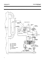
1
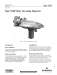
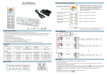
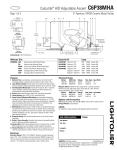
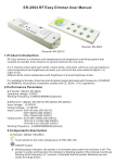
Instruction Manual
2502 Controllers
D200126X012
February 2015
Fisherr 2502 Controllers
Contents
Introduction . . . . . . . . . . . . . . . . . . . . . . . . . . . . . . . . . 2
Scope of Manual . . . . . . . . . . . . . . . . . . . . . . . . . . . . . 2
Description . . . . . . . . . . . . . . . . . . . . . . . . . . . . . . . . . 2
Specifications . . . . . . . . . . . . . . . . . . . . . . . . . . . . . . . 2
Educational Services . . . . . . . . . . . . . . . . . . . . . . . . . 2
Installation . . . . . . . . . . . . . . . . . . . . . . . . . . . . . . . . . . 4
249 Sensors . . . . . . . . . . . . . . . . . . . . . . . . . . . . . . . . 5
Uncrating . . . . . . . . . . . . . . . . . . . . . . . . . . . . . . . . . . 5
Controller Orientation . . . . . . . . . . . . . . . . . . . . . . . . 6
Controller‐Sensor Action . . . . . . . . . . . . . . . . . . . . . . 6
Mounting Caged Sensors . . . . . . . . . . . . . . . . . . . . . 7
Mounting Cageless Sensors . . . . . . . . . . . . . . . . . . . 9
Side‐Mounted Sensor . . . . . . . . . . . . . . . . . . . . . 9
Top‐Mounted Sensor . . . . . . . . . . . . . . . . . . . . 10
Supply Pressure . . . . . . . . . . . . . . . . . . . . . . . . . . . . 11
Prestartup Checks . . . . . . . . . . . . . . . . . . . . . . . . . . . 12
Adjustments . . . . . . . . . . . . . . . . . . . . . . . . . . . . . . . 13
Level Set Adjustment . . . . . . . . . . . . . . . . . . . . 13
Proportional Band Adjustment . . . . . . . . . . . . 13
Reset Adjustment . . . . . . . . . . . . . . . . . . . . . . . 13
Differential Relief Adjustment . . . . . . . . . . . . . 15
Calibration . . . . . . . . . . . . . . . . . . . . . . . . . . . . . . . . . . 15
Precalibration Requirements . . . . . . . . . . . . . . . . . 15
Wet Calibration . . . . . . . . . . . . . . . . . . . . . . . . . 15
Dry Calibration . . . . . . . . . . . . . . . . . . . . . . . . . 15
Controller and Torque Tube Arm
Disassembly . . . . . . . . . . . . . . . . . . . . . . . . . 16
Determining Suspended Weight
for Calibration . . . . . . . . . . . . . . . . . . . . . . . . 16
Calibration Procedure . . . . . . . . . . . . . . . . . . . . . . . 17
Startup . . . . . . . . . . . . . . . . . . . . . . . . . . . . . . . . . . . . . 18
Principle of Operation . . . . . . . . . . . . . . . . . . . . . . . . 19
2502 Controller . . . . . . . . . . . . . . . . . . . . . . . . . . . . 21
2502F Controller with Reset
Relief Valve . . . . . . . . . . . . . . . . . . . . . . . . . . . . . . 21
Maintenance . . . . . . . . . . . . . . . . . . . . . . . . . . . . . . . . 22
Troubleshooting . . . . . . . . . . . . . . . . . . . . . . . . . . . . 23
Removing Controller from Sensor . . . . . . . . . . . . . 24
www.Fisher.com
Figure 1. Fisher 2502 Controller Mounted on 249B
Sensor
2502 CONTROLLER
249B SENSOR
W8334
Changing Mounting Method . . . . . . . . . . . . . . . . .
Installing Controller on Sensor . . . . . . . . . . . . . . . .
Changing Proportional, Reset, or
Differential Relief Valve . . . . . . . . . . . . . . . . . .
Testing Relay Dead Band . . . . . . . . . . . . . . . . . . . . .
Changing Relay . . . . . . . . . . . . . . . . . . . . . . . . . . . . .
Replacing Bellows . . . . . . . . . . . . . . . . . . . . . . . . . .
Reversing Action . . . . . . . . . . . . . . . . . . . . . . . . . . .
Parts Ordering . . . . . . . . . . . . . . . . . . . . . . . . . . . . . . .
Parts Kits . . . . . . . . . . . . . . . . . . . . . . . . . . . . . . . . . . .
Parts List . . . . . . . . . . . . . . . . . . . . . . . . . . . . . . . . . . .
25
26
27
27
27
27
28
29
29
29
2502 Controllers
February 2015
Instruction Manual
D200126X012
Introduction
Scope of Manual
This instruction manual provides installation, operating, calibration, and maintenance procedures for Fisher 2502
pneumatic controllers (figure 1) used in combination with Fisher 249 level sensors.
This manual does not include regulator or sensor installation or maintenance procedures. For this information, refer to
the instruction manual for the appropriate regulator and 249 level sensor.
Do not install, operate, or maintain a 2502 controller without being fully trained and qualified in valve, actuator, and
accessory installation, operation, and maintenance. To avoid personal injury or property damage, it is important to
carefully read, understand, and follow all contents of this quick start guide, including all safety cautions and warnings.
If you have any questions about these instructions, contact your Emerson Process Management sales office before
proceeding.
Description
The 2502 controller described in this manual provides proportional‐plus‐reset and proportional‐plus‐reset with
differential relief valve control. The controller output is a pneumatic signal that operates a final control element. These
controllers are designed to control liquid level, the level of interface between two liquids, or density (specific gravity).
Each unit consists of a 249 liquid level sensor and a 2502 pneumatic controller.
Refer to the Principle of Operation section for a more comprehensive discussion of how the 2502 pneumatic controller
operates.
Specifications
Table 1 gives general specifications for 2502 controllers.
Educational Services
For information on available courses for the 2502 controller, as well as a variety of other products, contact:
Emerson Process Management
Educational Services, Registration
Phone: +1-641-754-3771 or +1-800-338-8158
e‐mail: [email protected]
http://www.emersonprocess.com/education
2
Instruction Manual
2502 Controllers
D200126X012
February 2015
Table 1. Specifications
Supply Pressure Requirement
Available Configurations
1.4 bar(1) (20 psig) for 0.2 to 1.0 bar (3 to 15 psig)
output signal or 2.4 bar(1) (35 psig) for 0.4 to 2.0 bar
(6 to 30 psig) output signal
2502: A direct‐acting controller which provides
proportional‐plus‐reset control
2502C: A 2502 with a level indicator assembly
2502F: A 2502 with a differential relief valve
Maximum Supply Pressure(2)
These products are also available with reverse action.
For example, 2502R, 2502CR, and 2502FR
3.4 bar (50 psig)
Supply Pressure Consumption(3)
Input Signal
At 1.4 bar (20 Psig)
Minimum: 0.11 normal m3/h (4.2 scfh) at proportional
band setting of 0 or 200 percent
Maximum: 0.72 normal m3/h (27 scfh) at proportional
band setting of 100 percent
At 2.4 bar (35 psig)
Minimum: 0.2 normal m3/h (7 scfh) at proportional
band setting of 0 or 200 percent
Maximum: 1.1 normal m3/h (42 scfh) at proportional
band setting of 100 percent
Liquid Level or Liquid‐to‐Liquid Interface Level: From
0 to 100 percent of displacer length—standard
lengths for all sensors are 356 mm (14 inches) or 813
mm (32 inches). Other lengths available depending
on sensor construction
Liquid Density: From 0 to 100 percent of
displacement force change obtained with given
displacer volume—standard volumes are 980 cm3 (60
inches3) for 249C and 249CP sensors, or 1640 cm3
(100 inches3) for most other 249 sensors; other
volumes available depending on construction
Performance
Hysteresis: 0.6 percent of output pressure change at
100 percent of proportional band
Repeatability: 0.2 percent of displacer length or
displacement force change
Dead Band: 0.05 percent of proportional band or
span
Typical Frequency Response: 4 Hz and 90‐degree
phase shift at 100 percent of proportional band with
output piped to typical instrument bellows using 6.1
meters (20 feet) of 6.4 mm (1/4 inch) tubing
Ambient Temperature Error: $1.5 percent of output
pressure change per 50_F (28_C) of temperature
change at 100 percent of proportional band when
using sensor with standard‐wall N05500 torque tube
with 249 sensors
Reset: Adjustable from 0.01 to 74 minutes per repeat
(100 to 0.01 repeats per minute)
Differential Relief (2502F and 2502FR Controllers
Only): Adjustable from 0.1 to 0.48 bar differential (2
to 7 psi) to relieve excessive difference between
proportional and reset pressures. Differential relief
can be switched between rising output pressure and
falling output pressure.
Output Signal
0.2 to 1.0 bar (3 to 15 psig) or 0.4 to 2.0 bar
(6 to 30 psig)
Action: Field reversible between direct (increasing
liquid or interface level or specific gravity increases
output pressure) and reverse (increasing liquid or
interface level or specific gravity decreases output
pressure)
Area Ratio of Relay Diaphragms
3:1
Supply Medium
Air or Natural Gas
Air: Supply pressure must be clean, dry air that meets
the requirements of ISA Standard 7.0.01. A maximum
40 micrometer particle size in the air system is
acceptable. Further filtration down to 5 micrometer
particle size is recommended. Lubricant content is
not to exceed 1 ppm weight (w/w) or volume (v/v)
basis. Condensation in the air supply should be
minimized
Standard Tubing Connections
1/4 NPT internal
Maximum Working Pressures (Sensors Only)
Natural Gas: Natural gas must be clean, dry, oil‐free,
and noncorrosive. H2S content should not exceed 20
ppm.
Consistent with applicable ASME
pressure/temperature ratings
(continued)
3
Instruction Manual
2502 Controllers
D200126X012
February 2015
Table 1. Specifications (continued)
Declaration of SEP
Hazardous Area Classification
2502 controllers comply with the requirements of
ATEX Group II Category 2 Gas and Dust
Fisher Controls International LLC declares this
product to be in compliance with Article 3 paragraph
3 of the Pressure Equipment Directive (PED) 97 / 23 /
EC. It was designed and manufactured in accordance
with Sound Engineering Practice (SEP) and cannot
bear the CE marking related to PED compliance.
Operative Ambient Temperatures(2)
Standard Construction: -40 to 71_C (-40 to 160_F)
High Temperature Construction: -18 to 104_C (0 to
220_F)
See figure 2
However, the product may bear the CE marking to
indicate compliance with other applicable European
Community Directives.
NOTE: Specialized instrument terms are defined in ANSI/ISA Standard 51.1 - Process Instrument Terminology.
1. Control and stability may be impaired if this pressure is exceeded.
2. The pressure/temperature limits in this document, and any applicable standard or code limitation should not be exceeded.
3. Normal cubic meters per hour (m3/hr) at 0_C and 1.01325 bar. Scfh=standard cubic feet per hour at 60_F and 14.7 psia .
Figure 2. Guidelines for Use of Optional Heat Insulator Assembly
800
60
71
70
593
500 _
TOO
HOT
HEAT INSULATOR
REQUIRED
-18
400
300
200
400
100
NO INSULATOR NECESSARY
0
0
USE INSULATOR (CAUTION! IF AMBIENT DEWPOINT IS ABOVE
PROCESS TEMPERATURE, ICE FORMATION MAY CAUSE INSTRUMENT
MALFUNCTION AND REDUCE INSULATOR EFFECTIVENESS.)
-20
-29
0
20
40
60
80
100
120
140
160
PROCESS TEMPERATURE ( F)
PROCESS TEMPERATURE ( F)
_
110
0
AMBIENT TEMPERATURE
20
30
40
50
0 (_C)10
PROCESS TEMPERATURE ( C)
-18 -10
_
0
-10
10
AMBIENT TEMPERATURE (_C)
20
30
40
50
93
60
70
80
90
593
110
0
800
500
TOO
HOT
HEAT INSULATOR
REQUIRED
400
300
200
400
100
NO INSULATOR NECESSARY
0
0
USE INSULATOR (CAUTION! IF AMBIENT DEWPOINT IS ABOVE PROCESS
TEMPERATURE, ICE FORMATION MAY CAUSE INSTRUMENT MALFUNCTION AND
REDUCE INSULATOR EFFECTIVENESS.)
-20
0
20
40
60
80
100
120
140
160
180
-29
200
AMBIENT TEMPERATURE (_F)
AMBIENT TEMPERATURE (_F)
B1413‐1
STANDARD CONTROLLER OR TRANSMITTER
NOTE: FOR SERVICE BELOW -29_C (-20_F) CONTACT FACTORY.
HIGH‐TEMPERATURE CONTROLLER OR TRANSMITTER
Installation
2502 controllers are used in combination with 249 sensors, and unless ordered separately, the controller will be
attached to the sensor.
WARNING
Wear protective eyewear, gloves and clothing whenever possible when performing any installation operations to avoid
personal injury.
Check with your process or safety engineer for any additional measures that must be taken to protect against process
media.
If installing into an existing application, also refer to the WARNING at the beginning of the Maintenance section in this
instruction manual.
4
Instruction Manual
2502 Controllers
D200126X012
February 2015
WARNING
Personal injury or property damage may result from fire or explosion if natural gas is used as the supply medium and
preventive measures are not taken. Preventive measures may include, but are not limited to, one or more of the following:
Remote venting of the unit, re‐evaluating the hazardous area classification, ensuring adequate ventilation, and the
removal of any ignition sources. For information on remote venting of this controller refer to page 11.
249 Sensors
D 249, 249B, 249BF, 249C, 249K, and 249L sensors side‐mount on the vessel with the displacer mounted inside a cage
(caged) outside the vessel.
D 249BP and 249CP sensors top‐mount on the vessel with the displacer hanging down into the vessel (cageless).
D The 249VS sensor side‐mounts on the vessel with the displacer hanging out into the vessel (cageless).
D The 249W sensor top‐mounts on the vessel or on a customer supplied cage.
External sensors provide more stable operation than do internal sensors for vessels with internal obstructions or
considerable internal turbulence.
WARNING
When replacing the sensor assembly, the displacer may retain process liquid or pressure. Personal injury or property
damage due to sudden release of pressure, contact with hazardous liquid, fire, or explosion can be caused by puncturing,
heating, or repairing a displacer that is retaining process pressure or liquid. This danger may not be readily apparent when
disassembling the sensor or removing the displacer. Before disassembling the sensor or removing the displacer, observe
the more specific warning provided in the sensor instruction manual.
Uncrating
Unless ordered separately, the controller will be attached to the sensor when shipped. Carefully uncrate the assembly.
CAUTION
If the sensor has a thin‐walled torque tube, always support the displacer if the travel stop must be removed. A thin‐walled
torque tube has a T stamped on the sensor end flange (not visible unless the controller is removed from the sensor).
Note
Caged sensors have a rod and block installed on each end of the displacer to protect the displacer in shipping. Remove these parts
before installing the sensor to allow the displacer to function properly.
Caged sensors will be shipped with the displacer installed in the cage. If the sensor is ordered with a tubular gauge
glass, the gauge glass will be crated separately and must be installed at the site. Be certain that the cage equalizing
connections are not plugged with foreign material.
5
Instruction Manual
2502 Controllers
D200126X012
February 2015
A caged sensor has a damping plate installed in the lower screwed or flanged connection to provide more stable
operation. If the process liquid could clog the plate opening with sediment, then remove the damping plate. For
screwed connections, use a 1/2‐inch hexagon wrench to unscrew the damping plate. For flanged connections, use a
screwdriver to pry the damping plate out of the flange.
A cageless sensor is shipped with the displacer separated from the sensor assembly. A displacer longer than 813 mm
(32 inches) is crated separately. A shorter displacer is crated with the sensor, but is not attached to the displacer rod.
Inspect the displacer and replace if it is dented. A dent may reduce the pressure rating of the displacer.
Controller Orientation
A controller is to be mounted with the vent opening pointing downward as shown in figure 3. This orientation is
necessary to ensure draining of accumulated moisture. The controller is attached to the sensor in one or the other of
the mounting positions shown in figure 4: Right hand (with the case to the right of the displacer when looking at the
front of the case) or left hand (with the case to the left of the displacer). The mounting position can be changed in the
field if required; refer to the appropriate sensor manual for instructions. Changing this mounting position will change
controller action from direct to reverse, or vice versa.
Figure 3. Pressure Connections
PRESSURE REGULATOR
LOCKNUT
ADJUSTING
SCREW
1/4‐18 NPT
SUPPLY CONNECTION
1/4‐18 NPT
OUTPUT CONNECTION
VENT
DRAIN VALVE
All caged sensors have a rotatable head. That is, the controller may be positioned at any of eight alternate positions
around the cage as indicated by the numbers 1 through 8 in figure 4. To rotate the head, remove the head flange bolts
and nuts and position the head as desired.
Controller‐Sensor Action
The following controller description is for right‐hand mounting. Left‐hand mounting produces an output signal with
the opposite action. Figure 4 shows cage head mounting positions.
For right‐hand mounting:
D Direct Action—Increasing liquid or interface level, or density, increases the output signal.
D Reverse Action—Decreasing liquid or interface level, or density, increases the output signal. A factory‐supplied
reverse‐acting unit has the suffix letter R added to the type number.
6
Instruction Manual
2502 Controllers
D200126X012
February 2015
Figure 4. Cage Head Mounting Positions
RIGHT‐HAND MOUNTING
1
LEFT‐HAND MOUNTING
67CFR FILTER/REGULATOR.
AH9150-A
A2613-2
Mounting Caged Sensor
Note
The cage must be installed plumb so that the displacer does not touch the cage wall. Should the displacer touch the cage wall, the
unit will transmit an erroneous output signal.
Note
If the controller is not mounted on the sensor, refer to the Installing Controller on Sensor section. This section also provides
instructions for adding a heat insulator to a unit.
Cage connections will normally be either NPS 1‐1/2 or 2 screwed or flanged. Figure 5 shows the combinations. With
flanged connections, use standard gaskets or other flat‐sheet gaskets compatible with the process liquid. Spiral wound
gaskets without compression‐controlling centering rings cannot be used for flanged connections.
7
Instruction Manual
2502 Controllers
D200126X012
February 2015
Figure 5. Cage Connection Styles
STYLE 1: TOP
AND BOTTOM
SCREWED: S1
FLANGED: F1
STYLE 2: TOP
AND LOWER SIDE
STYLE 3: UPPER
AND LOWER SIDE
SCREWED: S2
FLANGED: F2
SCREWED: S3
FLANGED: F3
STYLE 4: UPPER
SIDE AND BOTTOM
SCREWED: S4
FLANGED: F4
A1271-2
Mount the cage by running equalizing lines between the cage connections and the vessel (figure 6). A shutoff or hand
valve with a 1‐1/2 inch diameter or larger port should be installed in each of the equalizing lines. Also install a drain
between the cage and shutoff or hand valve whenever the bottom cage line has a liquid‐trapping low point.
On liquid or interface level applications, position the sensor so that the line marked FLOAT CENTER on the cage is
located as close as possible to the center of the liquid level or interface level range being measured. Also consider
installing a gauge glass either on the vessel, or on the sensor cage (if the cage is tapped for a gauge).
Figure 6. Caged Sensor Mounting
EQUALIZING LINE
CENTER OF LIQUID
OR INTERFACE LEVEL
SHUTOFF
VALVES
DRAIN VALVE
EQUALIZING LINE
DF5379‐A
A1883‐2
8
Instruction Manual
D200126X012
2502 Controllers
February 2015
Mounting Cageless Sensor
Note
If a stillwell is used, it must be installed plumb so that the displacer does not touch the wall of the stillwell. Should the displacer
touch the wall while the unit is in service, the unit will transmit an erroneous output signal.
Since the displacer hangs inside the vessel, provide a stillwell around the displacer if the liquid is in a state of
continuous agitation to avoid excessive turbulence around the displacer.
Note
Displacers used in an interface level application must be completely submerged during operation. If displacers aren't completely
submerged they will not calibrate or perform properly. To obtain the desired controller sensitivity may require using either a
thin‐wall torque tube, an oversized displacer, or both.
Note
If the controller is not mounted on the sensor, refer to the Installing Controller on Sensor section. This section also provides
instructions for adding a heat insulator to a unit.
Attach a cageless sensor to a flanged connection on the vessel as shown in figure 7. For interface or liquid level
applications, install a gauge glass on the vessel.
CAUTION
If the displacer is to be inserted into the vessel before being attached to the displacer rod, provide a suitable means of
supporting the displacer to prevent it from dropping into the vessel and suffering damage.
To help support a 249BP or 249CP displacer, install the displacer stem and stem end piece, or a threaded rod, into the
1/4 inch‐28 UNF threaded hole in the displacer spud or stem end piece (figure 8). On the 249BP with optional travel
stop, the stem end piece pins will secure the displacer as long as the travel stop plate is installed and the sensor head is
in position.
Side‐Mounted Sensor
If a stillwell is required (figure 7), the displacer must be attached to the displacer rod from inside the vessel. Connect
the displacer as shown in figure 8, locking the assembly with the cotter spring provided. If a stillwell is not required, the
displacer can be attached to the displacer rod before mounting the sensor to the vessel connection. The displacer may
then be swung out horizontally for insertion into the vessel. However, once the sensor is installed and the displacer
drops to a vertical position, the displacer may not be capable of being withdrawn for servicing later. Be sure there is
another access to the displacer to permit swinging it to a horizontal position or to permit disconnecting it from the
displacer rod.
9
Instruction Manual
2502 Controllers
D200126X012
February 2015
Figure 7. Cageless Sensor Mounting
TOP MOUNTED
SIDE MOUNTED
W9517‐1
SIDE VIEW (SHOWING STILLWELL)
CF5380‐A
A3893
SIDE VIEW (WITHOUT STILLWELL)
If an extension is used between the displacer spud and the displacer stem end piece, make sure the nuts are tight at
each end of the displacer stem extension. Install and tighten suitable bolting or cap screws in the flanged connection
to complete the installation.
Top‐Mounted Sensor
Figure 7 shows the installation of a top‐mounted cageless sensor. The displacer may be attached to the displacer rod
before installing the sensor on the vessel. Where the displacer diameter is small enough, it may be desirable to install a
long or sectionalized displacer through the sensor head access hole after the sensor is installed on the vessel. Connect
the displacer as shown in figure 8, locking the assembly with the cotter springs provided. If a stem is used between the
displacer as shown in figure 8, lock the assembly with the cotter springs provided. If a stem is used between the
displacer spud and the stem end piece, make sure the nuts are tight at each end of the stem. Install and tighten
suitable cap screws in the flanged connection to complete the installation.
10
Instruction Manual
2502 Controllers
D200126X012
February 2015
Figure 8. Displacer and Displacer Rod Connections
COTTER SPRING
DISPLACER ROD
DISPLACER
SPUD
DISPLACER
STEM EXTENSION
COTTER SPRING
LOCKING NUTS
DISPLACER ROD
DISPLACER SPUD
W0228‐1A
ALL OTHER TYPES
W9357
249VS SENSOR
Supply Pressure
WARNING
Do not overpressurize any system component. Personal injury or property damage may occur due to sudden pressure
release or explosion. To avoid damage, provide suitable pressure‐relieving or pressure limiting devices if supply pressure
can exceed the maximum supply pressure listed in table 1.
Personal injury or property damage may occur from an uncontrolled process if the supply medium is not clean, dry, oil‐free,
or non‐corrosive gas. While use and regular maintenance of a filter that removes particles larger than 40 micrometers in
diameter will suffice in most applications, check with an Emerson Process Management field office and industry instrument
air quality standards for use with corrosive gas or if you are unsure about the proper amount or method of air filtration or
filter maintenance.
Standard 2502 controllers come complete with supply and output pressure gauges and an integrally mounted 67CFR
filter regulator to reduce supply pressure from a maximum of 17.3 bar (250 psig) to the 1.4 or 2.4 bar (20 or 35 psig)
required. This regulator has built‐in relief and a standard 5‐micrometer filter to remove particles from the supply
source.
The output pressure connection is on the back of the controller case (figure 3). Pipe the supply pressure to the in
connection of the regulator mounted to the case back. Provide a clean, dry, and noncorrosive air or gas supply to the
controller.
After pressure connections have been made, turn on the supply pressure and check all connections for leaks.
Vent Assembly
WARNING
Personal injury or property damage could result from fire or explosion of accumulated gas, or from contact with hazardous
gas, if a flammable or hazardous gas is used as the supply pressure medium. Because the instrument case and cover
11
2502 Controllers
February 2015
Instruction Manual
D200126X012
assembly do not form a gas‐tight seal when the assembly is enclosed, a remote vent line, adequate ventilation, and
necessary safety measures should be used to prevent the accumulation of flammable or hazardous gas. However, a remote
vent pipe alone cannot be relied upon to remove all flammable and hazardous gas. Vent line piping should comply with
local and regional codes, and should be be as short as possible with adequate inside diameter and few bends to reduce case
pressure buildup.
CAUTION
When installing a remote vent pipe, take care not to overtighten the pipe in the vent connection. Excessive torque will
damage the threads in the connection.
The vent assembly (see figure 3) or the end of a remote vent pipe must be protected against the entrance of all foreign
matter that could plug the vent. Use 13 mm (1/2-inch) pipe for the remote vent pipe, if one is required. Check the vent
periodically to be certain it has not become plugged.
Prestartup Checks
WARNING
The following procedure requires taking the controller out of service. To avoid personal injury and property damage caused
by an uncontrolled process, provide some temporary means of control for the process before taking the controller out of
service.
Adjustment locations are shown in figure 9 unless otherwise indicated. When performing the checks open loop
conditions must exist. To obtain open‐loop conditions:
D make sure there is no process flow through the final control element, or
D disconnect the controller output signal line and plug the output connection.
During startup, it is necessary to change process levels to position the displacer from its maximum to its minimum
range of operations. Provide a means to change the process level or interface. If the process variable cannot be varied
sufficiently, follow the instructions in the Calibration section to simulate the process variable changes required for
these checks.
Make sure that the RAISE LEVEL dial on the controller is mounted with the correct side facing out. The dial is printed on
both sides with the arrow on one side pointing to the left and the arrow on the other side pointing to the right. Figure 9
shows the dial arrow positioned for a sensor that is mounted to the left of the controller; the arrow points to the left. If
the sensor is to the right of the controller, remove the two mounting screws, turn the dial over so the arrow points to
the right, then reinstall the mounting screws.
On a controller with optional level indicator assembly the travel indicator plate is printed on both sides. If the sensor is
to the left of the controller (right‐hand mounting), use the side of the plate that has the arrow pointing to the left. If
displacer is to right of controller (left‐hand mounting), use the side of the plate that has the arrow pointing to the
right.
1. Turn on the supply pressure and check that the controller supply gauge reads 1.4 bar (20 psig) for a 0.2 to 1.0 bar
(3 to 15 psig) output pressure range or 2.4 bar (35 psig) for a 0.4 to 2.0 bar (6 to 30 psig) output pressure range. If
12
Instruction Manual
D200126X012
2502 Controllers
February 2015
the pressure is incorrect, loosen the locknut of the filter/regulator (figure 3); turn the adjusting screw clockwise to
increase or counterclockwise to decrease pressure. Tighten the locknut after setting the pressure.
2. Turn the reset control to .05 minutes per repeat.
3. Locate the process variable at its minimum value (see table 2). Zero the proportional band and raise level controls.
Output pressure on direct‐acting controllers should be greater than zero but less than 0.2 bar (3 psig) for the 0.2 to
1.0 bar (3 to 15 psig) range or 0.4 bar (6 psig) for the 0.4 to 2.0 bar (6 to 30 psig) range. For reverse‐acting
controllers, the output pressure should be greater than 1.0 bar (15 psig) and less than 1.4 bar (20 psig) for the 0.2 to
1.0 bar (3 to 15 psig) range or greater than 30 psig (2.0 bar) and less than 3.4 bar (35 psig) for the 0.4 to 2.0 bar
(6 to 30 psig) range. If these conditions are not met recalibration may be desired. On a controller with indicator
assembly, the pointer should be over the low point on the indicator plate; slight adjustment might be necessary by
loosening the hex nut (key 40, figure 14), shifting the pointer, and retightening the nut.
4. Locate the process variable at its maximum value (see table 2). Output pressure on direct-acting controllers should
be greater than 1.0 bar (15 psig) and less than 1.4 bar (20 psig) for the 0.2 to 1.0 bar (3 to 15 psig) range or greater
than 2.0 bar (30 psig) and less than 3.4 bar (35 psig) for the 0.4 to 2.0 bar (6 to 30 psig) range. If these conditions
are not met, recalibration may be desired. On a controller with indicator assembly, the pointer should be over the
high point on the indicator plate; slight adjustment might be necessary by loosening the hex nut (key 40, figure 14),
shifting the pointer and retightening the nut.
On a controller with level indicator, the pointer should reflect the magnitude of the process variable; for instance,
with liquid or interface level covering 50 percent of the displacer, the pointer should be in the middle of the
high‐low scale. Slight plate adjustment might be necessary as described at the end of step 3.
5. If all prestartup checks are satisfactory proceed to the Startup section.
Adjustments
Controller adjustments are provided in this section. Refer to figure 9 for adjustment locations.
Level Set Adjustment
To perform the level adjustment, open the controller cover, loosen the knurled adjustment screw (see figure 9), and
rotate the adjustment lever around the RAISE LEVEL dial. To raise the fluid or interface level, or increase density, rotate
this knob in the direction of the arrows. To lower the level or decrease density, rotate the knob in the opposite
direction. This procedure is the same for both direct and reverse action controllers. Tighten the knurled screw.
Note
The RAISE LEVEL dial does not reflect actual fluid level in the tank or fluid level position on the displacer.
Proportional Band Adjustment
Proportional band adjustment is made to change the amount of displacement force change required to obtain full
output pressure change, by determining the percentage of pressure fed back to the proportional bellows. The
adjustment is performed by opening the controller cover and turning the percent proportional band knob (just below
the RAISE LEVEL dial).
Reset Adjustment
To adjust reset action (figure 9) turn the knob clockwise to decrease reset time (the minutes per repeat). Turn the
knob counterclockwise to increase the minutes per repeat. Increasing the minutes per repeat provides a slower reset
action.
13
Instruction Manual
2502 Controllers
D200126X012
February 2015
The reset rate adjustment dial is calibrated in minutes per repeat. By definition, this is the time in minutes required for
the reset action to produce a correction which is equal to the correction produced by proportional control action. This
is, in effect, the time in minutes required for the controller to increase (or decrease) its output pressure by an amount
equal to a proportional increase (or decrease) caused by a change in control conditions.
Figure 9. Controller Adjustments
POINTER ASSEMBLY
30A8943‐H
A1933
RAISE LEVEL DIAL FOR
LEFT‐HAND MOUNTING
2502C LEVEL INDICATOR WITH
RIGHT‐HAND MOUNTING
RESET ADJUSTMENT
MOUNTING
SCREWS
W5637
TYPICAL RIGHT‐HAND
MOUNTED 2502 CONTROLLER
14
21A6447‐A
A1903
ADJUSTING
SCREW
DIFFERENTIAL RELIEF VALVE
ON BACK OF 2502 CASE
1E8731‐C
1E8732‐C
A1897‐1
TRAVEL INDICATOR PLATE
FOR LEFT HAND MOUNTING
Instruction Manual
D200126X012
2502 Controllers
February 2015
Differential Relief Adjustment
The differential relief valve protrudes from the back of the controller case on a construction with an F in the type
number. Although normally factory‐set to relieve when the differential between the proportional and reset bellows
reaches 5 psi, the differential may be reduced down to 2 psi by turning the adjustment screw clockwise or increased up
to 7 psi by turning the screw counterclockwise. The minimum differential setting will yield the minimum set point
overshoot during startup.
Depending on the characteristics of the process, the relief valve can be positioned so that the arrow cast on the case
points either to the letters RE (reset) or to the letter P (proportional) on the back of the manifold. To reposition the
arrow, see figure 9. Remove the mounting screws. Reposition the differential relief valve to RE or P and reinstall the
mounting screws.
Calibration
Precalibration Requirements
Note
Calibration of a unit with a displacer designed for interface or density control must be conducted with the displacer completely
submerged in a liquid of the specific gravity for which the unit was designed.
To calibrate a controller, it is necessary to place the device into operation. This may be done on the vessel with the
actual service liquid. It may also be done in the shop, but other means of obtaining a displacement force change must
be provided. It must be done in the shop if the process variable is not available for calibration or if the process cannot
be varied for calibration. There are two methods of adapting the calibration procedure to shop calibration: wet and
dry.
Wet Calibration
Remove the entire controller and sensor assembly from the vessel. For caged sensors, pour the liquid into the cage.
For cageless sensors, suspend the displacer to an appropriate depth in a liquid having a specific gravity equal to that of
the process liquid.
If necessary, use water for wet calibration in the shop. However, this procedure requires compensation for the
difference between the specific gravity of the water and that of the process liquids. For example, assume that the
process liquid has a specific gravity of 0.7 and that wet calibration with water (specific gravity of 1.0) is desired. To
simulate a process level of 50 percent of the input span, a water level of 35 percent is required (0.7/1.0 x 50 percent =
35 percent).
Dry Calibration
Remove the controller and torque tube arm, as a single unit, from the cage or vessel. Then, wherever the standard
calibration instructions in this manual require a specific process variable for input to the sensor, simulate that variable
by suspending the proper weight (such as a can of sand) from the end of the displacer rod. Complete the following
Controller and Torque Tube Arm Disassembly and the Determining Suspended Weight for Calibration sections before
proceeding to the calibration procedure.
15
2502 Controllers
February 2015
Instruction Manual
D200126X012
Controller and Torque Tube Arm Disassembly
WARNING
To avoid personal injury from contact with the process liquid, lower the vessel level below the sensor torque tube arm, or
shut off the cage equalizing valves and drain the cage before proceeding. For closed vessels, release any pressure that may
be in the vessel before removing the sensor assembly.
When removing the displacer from the displacer rod or removing the controller and torque tube arm from the cage or
vessel, refer to the appropriate sensor instruction manual for assistance. The method of removing the displacer or
torque tube arm and attached controller will vary with the type of sensor.
For a caged sensor with top equalizing connection, it may be appropriate to remove the entire cage from the vessel
before disassembling.
CAUTION
If the displacer is to be disconnected from the displacer rod before the sensor assembly is removed from the cage or vessel,
provide a means of supporting the displacer to prevent it from dropping and suffering damage. The spuds or stem end
pieces on all displacers have holes suitable for inserting rods or other supports.
Additionally, a threaded rod may be installed into the 1/4‐inch 28 UNF threaded hole in the displacer spud or stem end piece
of top‐mounted cageless and all caged sensors. For some top‐mounted sensors with long displacers, it may also be possible
to remove the sensor through the access hole in the sensor head.
For the 249BP sensor with the travel stop, the stem end piece pins will secure the displacer as long as the travel stop plate is
installed and the sensor head is in position.
Determining Suspended Weight for Calibration
CAUTION
To avoid overloading a torque tube sized for interface or density applications under dry conditions, consult your Emerson
Process Management sales office for the maximum allowable substitute weight Ws that can be used with your particular
construction.
To determine the total weight that must be suspended from the displacer rod to simulate a certain condition of liquid
level or specific gravity, solve the following equation:
Ws = Wd ‐ [(0.0361) (V) (SP GR)]
where:
Ws = Total suspended weight in pounds (should never be less than 0.5 pounds). For a unit with a horizontal
displacer, make sure the center of gravity of the substitute weight is where it would be on the actual displacer.
Note
For liquid level control only, simulate the lower range limit of the input span by suspending the displacer from the displacer rod.
For other values of input span, remove the displacer and suspend the appropriate weight as determined in the equation above.
16
Instruction Manual
2502 Controllers
D200126X012
February 2015
Wd = Weight of the displacer, in pounds (determine by weighing displacer).
0.0361 = Weight of one cubic inch of water (specific gravity = 1.0), in pounds.
V = Volume of the displacer in cubic inches, that would be submerged at the level required by the calibration
procedure. Or,
V = π/4 (displacer diameter)2 x (length of displacer submerged)
SP GR = Specific gravity of the process liquid at operating temperature.
For interface level measurement, the equation becomes:
Ws = Wd ‐ [(0.0361) (V1) (SP GR1) + (0.0361) (Vh) (SP GRh)]
where:
V1 = Volume of the displacer submerged by the lighter liquid, in cubic inches.
Or,
V = π/4 (displacer diameter)2 x (length of the displacer submerged)
SP GR1 = Specific gravity of the lighter liquid at operating temperature.
Vh = Volume of the displacer submerged by the heavier liquid, in cubic inches.
Or,
V = π/4 (displacer diameter)2 x (length of the displacer submerged)
SP GRh = Specific gravity of the heavier liquid at operating temperature.
Calibration Procedure
WARNING
The following calibration procedure requires taking the controller out of service. To avoid personal injury and property
damage caused by an uncontrolled process, provide some temporary means of control for the process before taking the
controller out of service.
Figure 9 shows adjustment locations for the following steps, except as otherwise indicated. When calibrating, open
loop conditions must exist. One way to obtain an open loop is to place the final control element into manual control or
bypass it. If there is no provision for manual control, shut down the process. It is recommended that a test pressure
gauge be installed in the controller output line for subsequent calibration steps.
Several steps in these calibration procedures require setting the process variable at its minimum and maximum limits
according to table 2. Reverse‐acting controllers produce the opposite response.
Table 2. Minimum and Maximum Limits for Setting Process Variables
Application
Minimum Limit
Maximum Limit
Liquid level
Displacer must be completely out of liquid
Displacer must be completely submerged in liquid
Interface
Displacer must be completely submerged in the upper of
two process liquids
Displacer must be completely submerged in the lower of
two process liquids
Density
Displacer must be completely submerged in liquid having
highest specific gravity expected
Displacer must be completely submerged in liquid
having the lowest specific gravity expected
17
2502 Controllers
Instruction Manual
February 2015
D200126X012
1. Connect a supply pressure source to the controller and provide a supply pressure suitable for the sensing element
range: 1.4 bar (20 psig) for a 0.2 to 1.0 bar (3 to 15 psig) output pressure range or 2.4 bar (35 psig) for a 0.4 to 2.0
bar (6 to 30 psig) output pressure range.
2. Rotate the reset knob to 0.01 minutes per repeat.
3. Rotate the proportional band knob to zero.
4. Set the liquid at the minimum limit (dry displacer).
5. Turn the RAISE LEVEL knob to zero.
6. Adjust the nozzle until output pressure is between 0 and 0.2 bar for a 0.2 to 1.0 bar signal range (0 and 3 psig for a 3
to 15 psig signal range) or 0 and 0.4 bar for a 0.4 to 2.0 bar signal range (0 and 6 psig for a 6 to 30 psig signal range).
7. Set the liquid at the maximum limit (covered displacer).
8. Turn the RAISE LEVEL knob until the output pressure is 1.0 bar for a 0.2 to 1.0 bar signal range (15 psig for a 3 to 15
psig signal range) or 2.0 bar for a 0.4 to 2.0 bar signal range (30 psig for a 6 to 30 psig signal range).
9. The controller is within its calibration accuracy if the RAISE LEVEL knob is between the 9.0 and 10.0 positions.
10. If the controller is out of calibration, adjust the calibration adjuster as follows:
Note
Loosen the two calibration adjuster screws (key 45, figure 14), and slide the calibration adjuster (key 100, figure 14) in the desired
direction.
a. If output is below 1.0 bar for a 0.2 to 1.0 bar signal range (15 psig for a 3 to 15 psig signal range) or 2.0 bar for a
0.4 to 2.0 bar signal range (30 psig for a 6 to 30 psig signal range), move the adjustor a small distance away from
the pivot to increase span (movement should be away from the torque tube). Then repeat steps 4 through 9.
b. If output is above 1.0 bar for a 0.2 to 1.0 bar signal range (15 psig for a 3 to 15 psig signal range) or 2.0 bar for a
0.4 to 2.0 bar signal range (30 psig for a 6 to 30 psig signal range), move the adjustor a small distance toward the
pivot to decrease span (movement should be toward the torque tube). Then repeat steps 4 through 9.
Note
If the controller cannot be calibrated, look for other problems as described in the Troubleshooting section, such as a
nonperpendicular flapper‐nozzle condition, leaky connections, or a binding displacer rod. If none of these troubles is apparent, the
displacer or torque tube may be sized for a different set of service conditions. Ensure that the displacer is sized correctly for the
application.
Startup
Adjustment locations are shown in figure 9.
1. Set the RAISE LEVEL control to the desired control point as determined in prestartup checks step 4.
2. Set the percent proportional band control to 200.
3. Set the reset control to .05 minutes per repeat.
18
Instruction Manual
D200126X012
2502 Controllers
February 2015
4. Slowly open the downstream and upstream manual control valves in the pipeline and close the manual bypass valve
if one is used.
5. With the controller set at the desired control point, narrow the proportional band until a cycling condition exists.
Then broaden the proportional band slightly until stable control is obtained.
6. Adjust the reset control to obtain the highest reset setting without introducing cycling.
7. To ensure that the optimum proportional band and reset settings have been obtained, momentarily create a load
upset. If cycling occurs, broaden the proportional band slightly and repeat the load upset until stability is attained.
In general, the narrowest proportional band and the highest reset setting that will not produce cycling will provide
the best control.
Principle of Operation
All 2502 controllers use the same basic pressure‐balanced relay with a yoked double‐diaphragm assembly (figure 10).
This relay is connected so that supply pressure is fed to the inlet side of the relay valve and to the fixed restriction.
From this restriction, the air pressure goes into the relay chamber on the side of the large diaphragm, and to the
nozzle. As long as there is no pressure change on either diaphragm, the relay valve remains in equilibrium with both
the inlet and exhaust ends closed.
19
Instruction Manual
2502 Controllers
D200126X012
February 2015
Figure 10. Direct‐Acting Right‐Hand‐Mounted Fisher 2502‐249 Controller
TORQUE TUBE SHAFT
PROPORTIONAL
BELLOWS
FIXED
PIVOT
MOVABLE
ARM
PIVOTING
CROSS SPRINGS
FIXED
PIVOT
NOZZLE
BEAM AND
FLAPPER
LEVEL SET
ADJUSTMENT
CAM
RESET
VALVE
RESET BELLOWS
PROPORTIONAL
VALVE
FIXED
RESTRICTION
EXHAUST END
OF RELAY
VALVE
LARGE
DIAPHRAGM
OF ASSEMBLY
SUPPLY PRESSURE
OUTPUT PRESSURE
NOZZLE PRESSURE
INLET END
OF RELAY
VALVE
EXHAUST
PROPORTIONAL PRESSURE
RESET PRESSURE
VESSEL
INFLOW
20
SUPPLY
PRESSURE
REGULATOR
DIRECT‐ACTING
DIAPHRAGM
CONTROL VALVE
SMALL
DIAPHRAGM
OF ASSEMBLY
Instruction Manual
D200126X012
2502 Controllers
February 2015
The area ratio of the large diaphragm to the small diaphragm is 3 to 1. A 0.8 bar (12 psig) pressure change on the small
diaphragm need only be balanced by a 0.3 bar (4 psig) change on the large diaphragm.
A change in liquid level, interface level, or density changes the buoyant force exerted on the sensor displacer, which in
turn imparts a rotary motion through the torque tube shaft. The rotary motion is applied to the controller, which uses
a nozzle, bellows, and pneumatic relay to convert the rotary motion to a standard pneumatic output signal. The
output signal is sent to a final control element. In conjunction with this control element, 2502‐249 controller‐sensors
are capable of bringing the controlled variable back to a specific control point all the time.
The following descriptions show how the relay works in conjunction with the standard proportional‐plus‐reset
controller, and how the differential relief valve construction works.
2502 Controller
As long as inflow and outflow of the vessel are equal, the beam and flapper remain motionless and allow supply
pressure to bleed through the nozzle as fast as it enters the relay through the fixed restriction. A level or density
change either raises or lowers the displacer and pivots the beam and flapper with respect to the nozzle.
Note
The relay valve is double sided to control supply on one end and exhaust on the other.
An increase in level or density with direct action, or a decrease with reverse action, moves the beam and flapper closer
to the nozzle and restricts the escape of supply pressure. This builds up the loading differential on the side of the large
diaphragm and opens the relay valve to supply pressure inflow.
On the other hand, a decrease in level or density with direct action, or an increase with reverse action, moves the beam
and flapper away from the nozzle and permits supply pressure to bleed through the nozzle faster than it can enter
through the fixed restriction. This builds up the loading differential on the side of the small diaphragm, and opens the
relay valve to exhaust loading pressure.
The three‐way proportional valve can be opened and adjusted to allow some or all of the output pressure change to
feed back to the proportional bellows in order to change the proportional band of the controller. This pushes the beam
and flapper opposite the way it is being pivoted by the torque tube shaft, counteracting the pressure change in the
nozzle and again stabilizing the relay diaphragm pressure differential. The relay valve shuts off and maintains a new
output pressure according to the change in sensed displacer position.
A wide‐open proportional valve permits feedback of all the output change and produces 100 percent proportional
response. Closing of this valve produces smaller proportional responses, since part of the output change is vented
through the valve exhaust and only the remainder is available to reposition the bellows.
The reset valve can be adjusted to channel some or all of the proportional pressure into a reset bellows that opposes
proportional bellows action. This automatically dampens the effect of any proportional overcorrection by a set
amount per time interval, as long as there is a deviation from the control point.
Figure 10 illustrates these principles at work in a direct‐acting right‐hand‐mounted construction controlling liquid
inflow to a vessel, by means of a direct‐acting diaphragm‐actuated control valve. Nozzle positions and bellows
connections would be reversed for direct action with left‐hand mounting or reverse action with right‐hand mounting.
2502F Controller with Differential Relief Valve
This construction (figure 11) has a differential relief valve used to prevent proportional pressure from exceeding reset
pressure by more than a set value, a feature useful for intermittent control applications. Proportional valve output
registers in the outer chamber of the relief valve as well as in the proportional bellows.
21
Instruction Manual
2502 Controllers
D200126X012
February 2015
Figure 11. Fisher 2502F Controller with Differential Relief Valve
PROPORTIONAL
BELLOWS
MOVABLE
ARM
LEVEL SET
ADJUSTMENT
RELIEF VALVE
INNER CHAMBER
DIFFERENTIAL
RELIEF VALVE
FIXED
PIVOT
CAM
NOZZLE
PIVOTING
CROSS
SPRINGS
BEAM AND
FLAPPER
DIAPHRAGM
ASSEMBLY
RESTRICTION
RESET
BELLOWS
RESET VALVE
RELIEF
DIAPHRAGM
OUTER
CHAMBER
PROPORTIONAL
VALVE
FIXED RESTRICTION
EXHAUST END
OF RELAY VALVE
LARGE DIAPHRAGM
OF ASSEMBLY
SUPPLY PRESSURE
OUTPUT PRESSURE
NOZZLE PRESSURE
EXHAUST
PROPORTIONAL PRESSURE
CJ4081‐A
CU7387‐B
C0311‐2
INLET END
OF RELAY VALVE
SMALL
DIAPHRAGM
OF ASSEMBLY
RESET PRESSURE
A sudden increase in the output pressure will cause a rapid pressure increase in the proportional bellows and in the
outer relief valve chamber. If the outer chamber pressure exceeds that in the inner relief valve chamber by the amount
of the relief pressure setting, the relief diaphragm will move off the orifice in the relief valve, and the pressure in the
outer chamber will bleed into the reset system. This action provides quick relief of excessive proportional pressure and
reduces the time required by the system to return to the control point.
Maintenance
2502 controllers are used in combination with 249 sensors.
WARNING
Always wear protective eyewear, gloves and clothing whenever possible when performing maintenance to avoid personal
injury.
Personal injury or property damage due to sudden release of pressure, contact with hazardous liquid, fire, or explosion can
be caused by puncturing, heating, or repairing a displacer that is retaining process pressure or liquid. This danger may not
22
Instruction Manual
2502 Controllers
D200126X012
February 2015
be readily apparent when disassembling the sensor or removing the displacer. Before disassembling the sensor or
removing the displacer, observe the more specific warning provided in the sensor instruction manual.
When disconnecting any of the pneumatic connections, natural gas, if used as the supply medium, will seep from the unit
and any connected equipment into the surrounding atmosphere. Personal injury or property damage may result from fire
or explosion if natural gas is used as the supply medium and preventive measures are not taken.
Preventive measures may include, but are not limited to, one or more of the following:
D remote venting of the unit,
D re‐evaluating the hazardous area classification,
D the removal of any ignition sources, and
D ensuring adequate ventilation.
For information on remote venting of this controller refer to page 11.
Check with your process or safety engineer for any additional measures that must be taken to protect against process
media.
Troubleshooting
When troubleshooting, open loop conditions must exist unless otherwise stated. When monitoring the process
variable, use the most accurate level indicting device readily available. The output signal measuring device should
have a corresponding accuracy.
Table 3 lists some common operating faults, their probable causes, and corrective action.
Table 3. Troubleshooting Chart for Fisher 2502 Controllers
Fault
1. Process wanders or cycles around
setpoint.
Check
Correction
1.1 Proportional band or specific
gravity adjustment incorrect or
improperly tuned control loop.
Possible Cause
1.1 Insure the prestartup procedures
are completed correctly. Tune
control loop.
1.2 Supply pressure varying or
incorrect supply pressure setting.
1.2 Use input pressure gauge to
monitor stability. Make sure
regulator IN supply pressure is within
limits.
1.1 If stable control cannot be
attained and all other elements are
functionally correct, examine other
possible causes related to the
controller/transmitter.
1.2 Apply correct supply pressure. It
is recommended to use one
regulator per instrument.
1.3 Sensor not plumb and is in
contact with sidewall or leak in
displacer.
1.3 Check cage vessel and stillwell
installation, or for leaking displacer.
1.3 Make sure the displacer and
displacer rod hangs freely. Make sure
linkage is tight. Replace displacer if
leaking.
1.4 Relay malfunction.
1.4 Check for relay malfunction by
using the testing relay deadband
procedure
1.4 Depress plunger to clean out the
fixed restriction. Replace or repair
relay using the procedure in the
Maintenance section.
-continued-
23
Instruction Manual
2502 Controllers
D200126X012
February 2015
Table 4. Troubleshooting Chart for Fisher 2502 Controllers (continued)
Fault
2. Controller controlling off setpoint
or switching point.
Check
Correction
2.1 Supply pressure not set
correctly.
Possible Cause
2.1 Make sure regulator supply
pressure is set correctly. Make sure
regulator IN supply pressure is within
limits.
2.2 Leak in the controller loop.
2.2 Use soap and water to check for
internal and external leaks.
2.3 Insure the displacer is not filling
with process fluid.
2.1 Reset the supply regulator
pressure. If the condition occurs
again, rebuild or replace regulator.
Provide a regulator input pressure
within regulator limits.
2.2 Replace or repair leaking parts
as necessary.
2.3 Refer to sensor maintenance
procedures in the appropriate sensor
instruction manual.
2.4 Replace or tighten flapper
assembly as necessary and/or center
flapper on nozzle.
2.5 Change process variable back to
original specification or recalibrate.
If necessary, provide replacement
displacer of correct size and
recalibrate.
3.1 Reset the regulator pressure. If
problem reoccurs, replace or rebuild
the regulator. Insure regulator IN
supply pressure is within limits at all
operating levels.
3.2 Replace or tighten flapper
assembly as necessary and/or center
flapper on nozzle.
3.3 Change process variable back to
original specification or recalibrate.
If necessary, provide replacement
displacer of correct size and
recalibrate.
3.4 Depress plunger to clean out the
fixed restriction. Replace relay using
the procedure in the Maintenance
section.
2.3 Leaking displacer.
2.4 Flapper adjustment.
2.5 Process variable changed.
3. Controller cannot attain full
output range.
3.1 Supply pressure not set
correctly.
3.1 Make sure supply pressure is set
correctly. Make sure regulator IN
supply pressure is within limits.
3.2 Flapper adjustment.
3.2 Insure the flapper is not loose on
the torque tube shaft and is
centered on the nozzle.
3.3 Insure the process variable has
not changed from original
calibration settings or, from
displacer design specific gravity.
3.3 Process variable changed.
4. Controller remains at full or zero
output pressure.
2.4 Insure the flapper is not loose on
the torque tube shaft and is
centered on the nozzle.
2.5 Insure the process variable has
not changed from original
calibration settings or, displacer not
design specific gravity of process.
3.4 Relay malfunction.
3.4 Check for relay malfunction by
using the testing relay deadband
procedure.
3.5 Leaking controller loop.
3.5 Use soap and water to check for
internal and external leaks.
4.1 Insure the pressure gauges are
registering correctly.
4.1 Supply or output pressure gauge
malfunction
4.2 Flapper adjustment.
4.2 Insure the flapper is not loose on
the torque tube shaft. Insure the
flapper is centered on the nozzle.
3.5 Replace or repair leaking parts as
necessary.
4.1 Replace pressure gauges. Use
corrective action given in section 3
of this table.
4.2 Replace or tighten flapper
assembly as necessary and/or center
flapper on nozzle.
Removing Controller from Sensor
WARNING
To avoid personal injury in the following steps, turn off the supply pressure and carefully release any pressure trapped in
the controller before breaking any pressure connection. Provide a bypass for the control device if continuous operation is
required during maintenance.
Refer to figure 14 for key number locations, unless otherwise indicated.
1. Disconnect the supply and output pressure tubing from the controller.
2. Loosen the hex nut (key 40) that secures the operating arm base or pointer assembly (key 68 or 51) to the torque
tube rotary shaft. Do not lose the two link bearings (key 87, not shown).
24
Instruction Manual
D200126X012
2502 Controllers
February 2015
CAUTION
If the hex nut has not been loosened according to step 2, attempting to remove the controller from the sensor may bend
the rotary shaft or operating arm and linkage. Be careful that the back of the controller case or the heat insulator does not
drop down and bend the rotary shaft or shaft extension.
3. Remove any insulating tape from the joint between the controller case and the torque tube arm. Remove the four
cap screws (key 39, figure 12) that hold the controller or heat insulator to the torque tube arm. Pull the case straight
out from the torque tube arm, easing it over the shaft coupling (key 36, figure 12) if one is installed.
Figure 12. Heat Insulator Shown Installed on Fisher 249 Sensor
20A7423-C
4. If the controller has a heat insulator, remove the button head cap screws (key 40). Remove four washers (key 53)
and the insulator assembly (key 35).
Changing Mounting Method
WARNING
To avoid personal injury from contact with the process liquid, lower the vessel level below the torque‐tube arm before
proceeding. For closed vessels, release any pressure that may be above the liquid. Also, be careful to avoid overloading a
thin‐wall torque tube and/or oversized displacer.
Refer to figure 14 for key number locations.
25
2502 Controllers
February 2015
Instruction Manual
D200126X012
1. Remove the controller as described previously.
2. A controller is attached to the sensor in one or the other of the mounting positions shown in figure 4. Right hand
mount is with the case to the right of the displacer when looking at the front of the case. Left hand mount is with
the case to the left of the displacer. For a 249 sensor, remove the torque tube arm from the sensor or vessel and
reinstall the torque tube arm in the opposite position according to the appropriate instruction manual.
3. Check the desired control action to determine if it is also necessary to reverse the controller action. The nozzle
block and bellows tubing should be arranged in the proper position as shown in figure 13.
4. Remove the RAISE LEVEL dial, turn it over, and install it in the desired position. The arrow on it under the word
FLOAT should point toward the displacer. On a controller with indicator assembly, remove two screws (key 41,
figure 14), turn the front plate (key 54, figure 14) to the side that will have the float arrow pointing toward the
displacer, and secure the plate with the screws.
5. Install the controller according to the next section.
Installing Controller on Sensor
Note
If the installation is in a location that is not readily accessible and shop calibration is required, remove the torque tube arm from
the cage or vessel before mating the controller to the sensor. Install the controller on the torque tube arm in the shop; then
calibrate and return the controller and torque tube arm assembly to the installation.
Perform step 1 only if adding a heat insulator to a unit that does not have one. Key numbers in this step are shown in
figure 12, unless otherwise indicated.
1. To install the heat insulator, secure the shaft extension (key 37) to the torque tube assembly rotary shaft with the
shaft coupling (key 36). Tighten both set screws (key 38), with the coupling centered as shown in the figure. Then
mount the insulator assembly (key 35) on the controller case with four washers (key 53) and button‐head cap
screws (key 40). Tighten the screws.
CAUTION
In the following step, avoid bending the torque tube rotary shaft of the torque tube assembly. Bending or side loading of
this shaft could cause erroneous readings. Additionally, make sure the ball bearing assembly (key 12, figure 14) is removed
from the case (key 1, figure 14) to provide clearance when installing the case on the sensor.
2. Remove the bearing assembly (key 12) from the case (key 1).
3. Carefully slide the controller case straight in, guiding the bearing assembly (key 12), operating arm base or pointer
assembly (key 68 or 51, figure 14) over the rotary shaft and easing an attached heat insulator over the shaft
coupling (key 36) if necessary. Secure the case or insulator to the torque tube arm with the four cap screws (key 39).
Note
If a heat insulator is used, do not insulate its exterior.
4. On a unit without a heat insulator, tape the joint between the case and torque tube arm to minimize the entrance of
atmospheric moisture around the torque tube rotary shaft.
26
Instruction Manual
D200126X012
2502 Controllers
February 2015
5. Install and tighten the bearing assembly (key 12, figure 14) in the case (key 1, figure 14). Secure the operating arm
base or pointer assembly to the rotary shaft by tightening the hex nut (key 40, figure 14). Connect the supply and
output pressure tubing and perform the calibration procedure.
Changing Proportional, Reset, or Differential Relief Valve
1. Remove the proportional band valve assembly (key 36, figure 14) by unscrewing it from the relay base (key 23,
figure 14). Install the desired replacement assembly, or a 1/8 NPT pipe plug into the proportional band tapping if
testing relay dead band.
2. To change the reset restriction valve assembly (key 91), remove the two mounting screws (key 182) located on the
back side of case. Install the replacement valve assembly, and reconnect the tubing connections.
3. Remove the differential relief valve assembly (key 186, figure 14) by removing the two mounting screws (figure 9)
that anchor the valve to the manifold (key 184, figure 14). Install the valve with the arrow pointing to the same
letter(s) as before removal, unless it is desired to change the relief action.
Testing Relay Dead Band
1. Replace the proportional band adjustment assembly with a 1/8 NPT pipe plug according to the Changing
Proportional, Reset, or Differential Relief Valve section.
2. Turn on the supply pressure and set it to 1.4 or 2.4 bar (20 or 35 psig).
3. By changing the process variable and adjusting the RAISE LEVEL control, set the output pressure to 1.0 or 2.0 bar
(15 or 30 psig). While monitoring the output pressure, slowly change the process until an output pressure change
can just be detected, and record the value of the process variable at the detection point.
4. Change the process variable in the opposite direction until another output pressure change can be detected, and
again record the value of the process variable. If the difference between the two recorded values (the dead band) is
more than 0.2 percent of the maximum displacer length, the relay will have to be replaced or repaired according to
the Changing Relay and the Disassembling Relay sections.
5. Turn off the supply pressure, remove the pipe plug, and install the proportional band adjustment assembly.
Changing Relay
The relay may be removed for cleaning or replacement, and must be taken off to remove the lower bellows.
1. On a controller with indicator assembly, loosen the two lower screws of the relay case and slide out the indicator
base plate (key 53, figure 14).
2. Disconnect the tubing (key 11, figure 14) from the relay.
3. Remove both mounting screws, the relay, and the relay gasket (keys 43, 34, and 22, figure 14).
4. Install a new gasket, the replacement relay if necessary, and both mounting screws. Reconnect the tubing. On a
controller with indicator assembly, slide the base plate under the two lower screws of the relay case, align the plate
so that the pointer will read properly, and tighten the screws.
Replacing Bellows
Key numbers are shown in figure 14.
1. To gain access to the lower bellows, remove the relay according to the Changing Relay section.
2. Remove the upper and lower bellows frame screws (key 96) that hold both bellows assemblies to the bellows frame.
Unscrew each bellows from the spacer (key 98), being careful not to lose the O‐ring (key 57, not shown) from the
spacer end of the bellows.
3. Inspect each bellows and O‐ring and replace if necessary, using an unpainted bellows for a 0.2 to 1.0 bar (3 to 15
psig) range and a red bellows for a 0.4 to 2.0 bar (6 to 30 psig) range. Be sure to install the O‐ring at the spacer end
of the bellows.
27
Instruction Manual
2502 Controllers
D200126X012
February 2015
4. Install each bellows by screwing it down over the stud (key 97, not shown) protruding from each end of the spacer.
Secure with a bellows frame screw, and install the relay according to the Changing Relay section.
5. Perform the calibration procedure and any other necessary part of the calibration sequence.
Reversing Action
Note
The following procedure will be necessary to restore previous action if the mounting method has been changed. Key numbers are
shown in figure 14.
1. Remove two screws (keys 63 and 64), two seal rings (key 55), and the nozzle block (key 101). Check seal ring
condition and replace rings as necessary.
2. Install the nozzle block, seal rings, and screws on the opposite side of the beam as shown in figure 13. Disconnect
the proportional band tubing (key 76) and one of the two pieces of reset tubing (key 75) from the bellows frame
(key 94) and reconnect them in the proper orientation as shown in figure 13.
Figure 13. Nozzle, Flapper, and Tubing Arrangements for Various Actions and Mountings
SEAL SCREWS
SEAL SCREW RINGS
SEAL SCREW
RING
FLAPPER
HOOK
SEAL SCREW
SEAL
SCREW
RING
FLAPPER
HOOK
RESET
VALVE
RESET
VALVE
SEAL SCREW
RESET
TUBING
PROPORTIONAL
TUBING
RESET
TUBING
TO RELAY
TO PROPORTIONAL
VALVE
PROPORTIONAL
TUBING
TO RELAY
DIRECT ACTING—RIGHT HAND MOUNTING
REVERSE ACTING—LEFT HAND MOUNTING
AV2323‐A
AV2322‐A
B0995‐2
28
TO
PROPORTIONAL
VALVE
REVERSE ACTING—RIGHT HAND MOUNTING
DIRECT ACTING—LEFT HAND MOUNTING
Instruction Manual
2502 Controllers
D200126X012
February 2015
Note
Beam overtravel can jam the flapper against the nozzle if the following step is not performed.
3. Remove the flapper screw (key 93), lockwasher (key 84), and flapper (key 60). Invert the flapper so that the flapper
hook is on the opposite side of the beam from the nozzle (key 58), and secure with the lockwasher and screw.
4. Perform the calibration procedure and any other necessary part of the calibration sequence.
Parts Ordering
Whenever corresponding with your Emerson Process Management sales office about this equipment, always mention
the controller type number and the serial number found on the unit nameplate (figure 9). When ordering replacement
parts, also state the complete 11‐character part number of each required part as found in the following parts list.
WARNING
Use only genuine Fisher replacement parts. Components that are not supplied by Emerson Process Management should
not, under any circumstances, be used in any Fisher instrument. Use of components not supplied by Emerson Process
Management may void your warranty, might adversely affect the performance of the instrument, and could cause personal
injury and property damage.
Parts Kits
Description
Parts List
Part Number
Controller Parts Kit
Contains keys 12, 15, 21, 24, 38, 55, 57, 58, 60, 62, 63, 64,
77, 79, 84, 86, 87, 93, 101, and 187
Standard Temperature
R2502X00L52
High Temperature
R2502X00H52
Relay Replacement Kit
Contains keys 22, 43, and the relay assembly
Standard Temperature
High Temperature
RRELAYX0L22
RRELAYX0H22
Heat Insulator Parts Kit
Contains keys 35, 36, 37, 38, 39, 40, and 53
R2500XH0012
2500 Controller Cover Gasket Kit
Contains qty. 5 cover gaskets, key 21
R2500CVR012
Key
Description
Note
Part numbers are shown for recommended spares only. For part
numbers not shown, contact your Emerson Process Management sales
office.
Controller Common Parts
(figure 14)
1
2
3
4
5
6
7
8
Pilot Case Back, zinc
2502 and 2502C
2502F
Pilot Case Cover, aluminum
Door Handle, steel, pl
Door Handle Shaft (not shown),
stainless steel
Machine Screw, stainless steel
Washer Spring, stainless steel
Door Hook, steel, pl
Elastic Stop Nut, steel, pl
29
Instruction Manual
2502 Controllers
D200126X012
February 2015
Key
Description
9
11
12*
13
14*
15*
Drive Pin, (2 req'd)
Relay Tubing, stainless steel
Ball Bearing Ass'y, brass, pl
Retaining Ring, steel, pl (2 req'd)
Gauge Glass, glass, (2 req'd)
Gauge Glass Gasket, chloroprene (2 req'd)
19*
Pressure Gauge (2 req'd)
Triple Scale
Brass
0‐30 psig/0‐0.2MPa/0‐2.0 bar
0‐60 psig/0‐0.4MPa/0‐4.0 bar
Stainless steel
0‐30 psig/0‐0.2MPa/0‐2.0 bar
0‐60 psig/0‐0.4MPa/0‐4.0 bar
Dual Scale
Brass
0‐30 psig/ 0 to 2 kg/cm2
0‐60 psig/ 0 to 4 kg/cm2
Stainless steel
0‐30 psig / 0 to 2 kg/cm2
21*
22*
23
24*
29
31
34
35
36
37
Cover Gasket, chloroprene
Relay Gasket
Standard, chloroprene
High‐temperature, silicone
Relay Base, aluminum
Relay Base Gasket (not shown)
Standard, chloroprene
High‐temperature, silicone
Drive‐lok Pin, stainless steel
Shaft Clamp Screw, stainless steel
Pilot Relay
Standard
High‐temperature
Level Adjustment Ass'y
Proportional Valve Ass'y
Pressure Regulator (67CFR)
38A* Filter Gasket (not shown)
Standard, chloroprene
High‐temperature, silicone
38B Spacer (not shown)
38C* O‐Ring
Standard, nitrile
High‐temperature, fluorocarbon
39
40
41
42
43
30
Cap Screw (not shown), steel, pl (2 req'd)
Hex Nut, stainless steel
Screw, steel, pl, 2502C
and 2502FC (2 req'd)
Machine Screw, stainless steel, (8 req'd)
Machine Screw, stainless steel (2 req'd)
Part Number
1C8983000A2
0T019206042
0T019104082
Key
Description
44
45
47
49
50
51
Machine Screw, steel, pl (4 req'd)
Machine Screw, stainless steel (2 req'd)
Spring (not shown), stainless steel
Machine Screw, stainless steel (13 req'd)
Screen, stainless steel
Pointer Ass'y, 2502C and 2502FC,
stainless steel/brass, pl
53
Base Plate, aluminum
2502C and 2502FC
Front Plate, aluminum
2502C and 2502FC
O‐Ring, (3 req'd)
Standard, nitrile
High‐temperature, fluorocarbon
O‐Ring (not shown)
Standard, nitrile
High‐temperature, fluorocarbon
Nozzle, stainless steel
Beam, steel, pl
Flapper, K93600 alloy
Flapper Base, stainless steel
Connecting Link, N04400
Sealing Screw, stainless steel
Screw, stainless steel
54
11B8577X012
11B8577X022
11B8583X012
11B8583X022
11B8577X042
11B8577X052
11B8583X032
1C919806432
1C897403012
1N873804142
1C897303012
1N873904142
55*
57*
58*
59
60
61
62*
63
64
65*
66
67
68
69
70
71*
72
1C898603012
1N874004142
1E591406992
1E5914X0062
74
75
76
77*
78
79*
80
81
82
Bellows Ass'y, brass (2 req'd)
0.2 to 1.0 bar (3 to 15 psig)
0.4 to 2.0 bar (6 to 30 psig)
Level Set Arm, steel, pl
Operating Arm, steel, pl
Operating Arm Base, brass, pl
2502 and 2502F
Level Set Pivot Pin, stainless steel
Pivot Base, steel, pl
Spring Washer, stainless steel
Washer, stainless steel
2502 (2 req'd)
2502C and 2502FC (4 req'd)
Washer, stainless steel, (6 req'd)
Reset Tubing Ass'y, stainless steel (2 req'd)
Proportional Band Tubing Ass'y, stainless steel
Bellows Frame Gasket (not shown)
Standard, chloroprene
High‐temperature, silicone
Spacer (not shown), brass
Bellows Gasket (2 req'd)
Standard, chloroprene
High‐temperature, silicone
Machine Screw, stainless steel, (4 req'd)
Machine Screw (not shown)
stainless steel, (2 req'd)
Machine Screw, stainless steel, (4 req'd)
*Recommended spare parts
Part Number
1D687506992
1N430406382
1E222606992
1N838706382
1U639135132
1L379641012
14A5726X012
14A5726X032
1H885128982
1H265403012
1N873504142
1D397003012
1N873604142
Instruction Manual
2502 Controllers
D200126X012
February 2015
Figure 14. Fisher 2502 Controller Constructions
30A8942‐H
TYPICAL CONTROLLER
DETAIL OF RELIEF VALVE ASSEMBLY
ON 2502F CONTROLLER
43A2366‐H
DETAIL OF LEVEL INDICATOR ASSEMBLY
ON 2502C CONTROLLER
30A8943‐H
31
Instruction Manual
2502 Controllers
D200126X012
February 2015
Key
83
84
85
86
87*
88
89
91
93
94
95
96
97
98
99
100
101
180
181
182
Description
Lock Washer, stainless steel (2 req'd)
Lock Washer, stainless steel
Cap Screw, stainless steel, not shown (4 req'd)
Machine Screw, stainless steel (2 req'd)
Link Bearing (not shown)
stainless steel (2 req'd)
Machine Screw (not shown),
stainless steel, (4 req'd)
Machine Screw, stainless steel, (2 req'd)
RESET Restriction Valve Ass'y
2502 and 2502C
2502F and 2502FC
Machine Screw, stainless steel
Bellows Frame, aluminum
Bellows Frame Base (not shown), steel, pl
Bellows Screw, brass, pl (2 req'd)
Bellows Stud (not shown), brass
Spacer, zinc
Cross Spring, stainless steel (2 req'd)
Calibration Adjuster, zinc
Reversing Block, zinc
Pipe Nipple (not shown) 2502F
and 2502FC, steel
Relief Tubing Ass'y, 2502F and
2502FC, stainless steel
Machine Screw, stainless steel, (2 req'd)
2502 and 2502C (not shown)
2502F and 2502FC
Part Number
Key
Description
183*
184
185
186
O‐Ring (2 req'd), 2502F and 2502FC
Manifold, aluminum, 2502F and 2502FC
Manifold Nipple, aluminum, 2502F and 2502FC
Differential Relief Valve Ass'y, 2502F
and 2502FC
Standard
High temperature
1L379546202
Part Number
1D6875X0132
187
Sleeve, plastic
188* 0‐Ring, 2502F and 2502FC
215
Nameplate, metal
1C8538X0132
Pipe Plug, 2502 and 2502C
1D754828982
Heat Insulator (figure 12)
Note
All Heat Insulator parts are included in the Heat Insulator Parts Kit.
35
36
37
38
39
40
53
Heat Insulator Assembly, stainless steel
Shaft Coupling, stainless steel
Shaft Extension, N05500
Set Screw, stainless steel (2 req'd)
Cap Screw, steel, pl (4 req'd)
Cap Screw, steel, pl (4 req'd)
Washer, carbon steel, pl (4 req'd)
*Recommended spare parts
Neither Emerson, Emerson Process Management, nor any of their affiliated entities assumes responsibility for the selection, use or maintenance
of any product. Responsibility for proper selection, use, and maintenance of any product remains solely with the purchaser and end user.
Fisher is a mark owned by one of the companies in the Emerson Process Management business unit of Emerson Electric Co. Emerson Process Management,
Emerson, and the Emerson logo are trademarks and service marks of Emerson Electric Co. All other marks are the property of their respective owners.
The contents of this publication are presented for informational purposes only, and while every effort has been made to ensure their accuracy, they are not
to be construed as warranties or guarantees, express or implied, regarding the products or services described herein or their use or applicability. All sales are
governed by our terms and conditions, which are available upon request. We reserve the right to modify or improve the designs or specifications of such
products at any time without notice.
Emerson Process Management
Marshalltown, Iowa 50158 USA
Sorocaba, 18087 Brazil
Chatham, Kent ME4 4QZ UK
Dubai, United Arab Emirates
Singapore 128461 Singapore
www.Fisher.com
32
E 2007, 2015 Fisher Controls International LLC. All rights reserved.