1
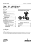
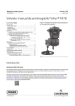
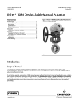
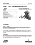
Instruction Manual
1078 Actuator
D101329X012
October 2012
Fisherr 1078 Declutchable Manual Actuator
Contents
Introduction . . . . . . . . . . . . . . . . . . . . . . . . . . . . . . . . . 1
Scope of Manual . . . . . . . . . . . . . . . . . . . . . . . . . . . . . 1
Description . . . . . . . . . . . . . . . . . . . . . . . . . . . . . . . . . 2
Specifications . . . . . . . . . . . . . . . . . . . . . . . . . . . . . . . 3
Educational Services . . . . . . . . . . . . . . . . . . . . . . . . . 3
Installation . . . . . . . . . . . . . . . . . . . . . . . . . . . . . . . . . . 7
Converting An Existing Power Actuator for use
with the Fisher 1078 Manual Actuator . . . . . . . . 8
Installing the Manual Actuator . . . . . . . . . . . . . . . . . 9
Operation . . . . . . . . . . . . . . . . . . . . . . . . . . . . . . . . . . 10
Engaging and Disengaging the Manual Actuator . 11
Engaging the Manual Actuator . . . . . . . . . . . . 11
Disengaging the Manual Actuator . . . . . . . . . 11
Maintenance . . . . . . . . . . . . . . . . . . . . . . . . . . . . . . . . 12
Lubrication . . . . . . . . . . . . . . . . . . . . . . . . . . . . . . . . 12
Parts Ordering . . . . . . . . . . . . . . . . . . . . . . . . . . . . . . . 13
Parts List . . . . . . . . . . . . . . . . . . . . . . . . . . . . . . . . . . . 13
Manual Actuator Assembly . . . . . . . . . . . . . . . . . . . 13
Field Mounting Parts . . . . . . . . . . . . . . . . . . . . . . . . 14
For 1051 and 1052 Size 33 Actuators . . . . . . . 14
For 1066 and 1066SR Actuators . . . . . . . . . . . 14
For 1061; and 1051 & 1052 Sizes 40, 60,
and 70 Actuators . . . . . . . . . . . . . . . . . . . . . 14
Figure 1. Fisher 1078 Manual Actuator Mounted on
a 1052 Size 33 Actuator
W6244-1
Introduction
Scope of Manual
This instruction manual includes installation, operation, and maintenance information for the Fisher 1078
declutchable manual actuator (figure 1). Refer to separate instruction manuals for instructions covering the power
actuator and control valve.
Do not install, operate, or maintain a 1078 declutchable manual actuator without being fully trained and qualified in
valve, actuator, and accessory installation, operation, and maintenance. To avoid personal injury or property damage,
it is important to carefully read, understand, and follow all the contents of this manual, including all safety cautions
and warnings. If you have any questions about these instructions, contact your Emerson Process Management sales
office before proceeding.
www.Fisher.com
Instruction Manual
1078 Actuator
October 2012
D101329X012
Table 1. Specifications
Available Configurations
Direct and reverse acting; see Handwheel Rotation in
this specification table
Actuator Sizes
See tables 2, 3, 4 and 5
Acceptable Coupling Shaft Diameters
See tables 2, 3, 4 and 5
Power Actuator Compatibility
See tables 2, 3, 4 and 5
Output Torque
See tables 2, 3, 4 and 5
Wheel-Rim Force
See tables 2, 3, 4 and 5
Handwheel Turns Required For Full Rotation
See tables 2, 3, 4 and 5
Handwheel Rotation
Direct Acting Construction: Clockwise handwheel
rotation closes the valve (produces clockwise valve
shaft rotation)
Reverse Acting Construction: Clockwise handwheel
rotation closes the valve (produces counterclockwise
valve shaft rotation)
Decide whether Direct or Reverse Action is required
by referring to the appropriate valve or power
actuator instruction manual and determining valve
rotation.
Maximum Output Rotation
90 degrees; limited by travel stops in the power
actuator
Standard Mounting Positions
1051 (size 33) and 1052 (size 33): handwheel down
1051 (sizes 40 and 60) and 1052 (sizes 40, 60, and
70)(1): handwheel down (std) or handwheel
right-hand or left-hand mount (optional)
1061 (sizes 30, 40, 60, 68, 80, and 100)(1):
handwheel down (std) or handwheel right-hand or
left-hand mount (optional)
1066 and 1066SR: handwheel to the left or, with a
Fisher 67CFR, handwheel down
Approximate Weights without Handwheel
Size AAA: 2.7 kg (6 lb)
Size AA: 6.8 kg (15 lb)
Size A: 9.5 kg (21 lb)
Size 2A: 13.6 kg (30 lb)
Size 1A: 15.9 kg (35 lb)
Size B: 23.1 kg (51 lb)
Size C: 29.9 kg (66 lb)
Size D: 63.5 kg (140 lb)
Size II-FA: 81.6 kg (180 lb)
Handwheel Weight
6-inch: 1.8 kg (4 lb)
8-inch: 2.3 kg (5 lb)
12-inch: 3.2 kg (7 lb)
16-inch: 6.8 kg (15 lb)
24-inch: 5.4 kg (12 lb)
30-inch: 6.4 kg (14 lb)
36-inch: 7.3 kg (16 lb)
1. If a positioner is used, the right-hand or left-hand mounting option will be limited to the side away from the positioner.
Description
The 1078 manual actuator, shown in figures 1 and 2, is a declutchable unit for manual operation of control valves and
equipment that use power actuators. The 1078 manual actuator mounts directly to Fisher 1051 sizes 33, 40, and 60;
1052 sizes 33, 40, 60, and 70; 1061 sizes 30, 40, 60, 68, 80, and 100; and to all sizes of 1066 or 1066SR actuators. The
1078 manual actuator can be engaged to allow manual operation of the valve when the power actuator is not in use. It
can be disengaged to allow automatic operation of the valve by the power actuator. The mechanism used allows
manual actuator engagement at any point of power actuator rotation.
For 1051 size 33, 1052 size 33, 1066, and 1066SR actuators, coupling to the power actuator is via a flatted shaft
installed in the lever or hub. The dimensions of these shafts are the same as those used with H mounting adaptations.
The stub shaft fits into a square broach in the manual actuator sector, and spacers secure the shaft in the appropriate
position.
2
Instruction Manual
1078 Actuator
D101329X012
October 2012
H and J mounting adaptations are the mounting methods normally used to mount 1051, 1052, 1061, 1066 and
1066SR actuators on equipment and valves not manufactured by Emerson Process Management. F and G mounting
adaptations are the mounting methods normally used to mount 1051, 1052, 1061, 1066 and 1066SR actuators on
valves manufactured by Emerson Process Management.
For all sizes of the 1066 or 1066SR actuators, coupling to the power actuator is in the hub of the 1066 or 1066SR
actuator.
Figure 2. Fisher 1078 Declutchable Manual Actuator Mounted on a 1052 Size 40 Actuator and V500 Valve
W6283
Specifications
1078 manual actuator specifications are given in table 1. Specifications for a control valve assembly as it comes from
the factory appear on a nameplate attached to the power actuator.
Educational Services
For information on available courses for 1078 manual actuators, as well as a variety of other products, contact:
Emerson Process Management
Educational Services, Registration
P.O. Box 190; 301 S. 1st Ave.
Marshalltown, IA 50158-2823
Phone: 800-338-8158 or
Phone: 641-754-3771
FAX: 641-754-3431
e-mail: [email protected]
3
Instruction Manual
1078 Actuator
October 2012
D101329X012
Table 2. Fisher 1051, 1052, and 1066SR Actuator Size Selection and Specifications for Sizes AAA, AA, and A
MANUAL
ACTUATOR
SIZE
(max output
torque)
SHAFT SIZE(1)
POWER
ACTUATOR(2)
mm
12.7
15.9
19.1
(22.2, 25.4)
Inch
1/2
5/8
3/4
(7/8, 1)
12.7
15.9
19.1
(22.2, 25.4)
1/2
5/8
3/4
(7/8, 1)
1052
33
12.7
15.9
19.1
(22.2, 25.4)
1/2
5/8
3/4
(7/8, 1)
1066SR
AA
(4800 in.lbs)
12.7
15.9
19.1
(22.2, 25.4)
1/2
5/8
3/4
(7/8 ,1)
A
(8200 in.lbs)
19.1
3/4
(22.2, 25.4)
(7/8, 1)
(31.8, 38.1) (1-1/4,1-1/2)
AAA
(2400 in.lbs)
Type
Size
1051
33
GEAR
RATIO
HANDWHEEL
DIAMETER
mm
For Maximum
Torque
For Less Than
Maximum Torque
Degrees
NSm
143
223
271
271
LbfSin
1271
1981
2400
2400
N
157
245
298
298
Pounds
35
55
67
67
N
Pounds
60
90
190
270
271
271
1681
2391
2400
2400
209
297
298
298
47
66
67
67
Divide
NSm
req'd by
0.91
Divide
lbfSin req'd
by 36
4
6
20
169
249
271
271
1495
2205
2400
2400
186
274
298
298
42
61
67
67
1066SR
27
34.1
305
12
283
363
464
541
2515
3225
4120
4800
218
279
357
416
49
63
81
94
Divide
NSm
req'd by
1.3
Divide
lbfSin req'd
by 51
5.7
8.5
1066SR
75
32.1
610
24
717
926
926
6350
8200
8200
299
385
385
66
85
85
Divide
Divide
NSm req'd lbfSin req'd
by 2.4
by 96
5.3
8
24.1
Inch
MAXIMUM
TORQUE(3)
HANDWHEEL
TURNS FOR
ROTATION
WHEEL-RIM-FORCE
305
12
1. Requires flatted shaft as in the H mounting adaptation.
2. Field conversion of actuators for F and G mounting adaptations requires installation of new parts. The 1051 or 1052 Size 33 actuator requires installation of appropriate lever and stub shaft.
The 1066 actuator requires installation of appropriate hub assembly.
3. Compare table value with torque requirements of the valve plus the torque required to compress the power actuator spring (from Fisher Catalog 14). Note that dynamic torque of the valve
may have a positive or negative effect on total torque required.
Table 3. Fisher 1066 Actuator Size Selection and Specifications for Sizes AAA, AA, and A
MANUAL
ACTUATOR
SIZE
(max
output
torque)
SHAFT SIZE(1)
POWER
ACTUATOR(2)
Type
GEAR
RATIO
mm
Inch
AAA
(2400
in.lbs)
12.7
15.9
19.1
(22.2, 25.4)
1/2
5/8
3/4
(7/8, 1)
Size
1066
20
24.1
AA
(4800
in.lbs)
12.7
15.9
19.1
(22.2, 25.4)
1/2
5/8
3/4
(7/8, 1)
1066
27
A
(8200
in.lbs)
19.1
(22.2, 25.4)
(31.8, 38.1)
3/4
(7/8, 1)
(1-1/4, 1-1/2)
1066
75
HANDWHEEL
DIAMETER
mm
MAXIMUM
TORQUE(3)
HANDWHEEL
TURNS FOR
ROTATION
WHEEL-RIM-FORCE
For Maximum
Torque
For Less Than Maximum
Torque
Degrees
Inch
NSm
LbfSin
N
Pounds
N
Pounds
60
90
305
12
58
138
239
271
515
1225
2120
2400
62
151
262
298
14
34
59
67
Divide
NSm req'd
by 0.91
Divide
lbfSin req'd
by 36
4
6
34.1
305
12
58
138
239
467
515
1225
2120
4140
44
106
182
360
10
24
41
81
Divide
NSm req'd
by 1.3
Divide
lbfSin req'd
by 51
5.7
8.5
32.1
610
24
239
467
926
2120
4140
8200
98
191
385
22
43
85
Divide
NSm req'd
by 2.4
Divide
lbfSin req'd
by 96
5.3
8
1. Requires flatted shaft as in the H mounting adaptation.
2. Field conversion of actuators for F and G mounting adaptations requires installation of new parts. The 1066 actuator requires installation of appropriate hub assembly.
3. Compare table value with torque requirements of the valve plus the torque required to compress the power actuator spring (from Fisher Catalog 14). Note that dynamic torque of the valve
may have a positive or negative effect on total torque required.
4
Instruction Manual
1078 Actuator
D101329X012
October 2012
Table 4. Fisher 1051 and 1052 Actuator Size Selection and Specifications for Sizes 2A, 1A, B, and C
MANUAL
ACTUATOR
SIZE
(max output
torque)
2A
(4800 in.lbs)
1A
(8200 in.lbs)
B
(12,000
in.lbs)
C
(18,000
in.lbs)
SHAFT SIZE
mm
Inch
12.7
1/2
15.9,
14.3x
9.5
5/8,
9/16x
5/8
19.1
3/4(3)
(22.2,
25.4)
POWER
ACTUATOR(1)
Type
1051
GEAR
RATIO
Size
mm
N
Pounds
99
460
4075
354
80
541
4800
416
94
(7/8, 1)
467(4)
4140(4)
360
81
31.8
1-1/4
541
4800
416
94
12.7
1/2
429
3795
330
74
15.9,
14.3x
9.5
5/8,
9/16x
5/8
509
4505
392
88
19.1
3/4(3)
541
4800
416
94
(22.2,
25.4)
(7/8, 1)
467(4)
4140(4)
360
81
31.8
1-1/4
541
4800
416
94
1052
40
31.8
1-1/4
(22.2,
25.4)
(7/8, 1)
1051
1052
60
60
31.8,
28.6x
31.8
1-1/4,
1-1/8x
1-1/4
38.1
31.8x
38.1
1-1/2,
1-1/4x
1-1/2
1051
60
1052
60
(44.4,
50.8),
39.7
x44.5
(1-3/4,
2),
1-9/16
x1-3/4
1052
70
1051
1052
1052
60
60
70
1051
1052
1-1/4
1-1/2,
(1-3/4,
2)
31.8
1-1/4
(44.4,
50.8)
(1-3/4,
2)
12
34:1
1051
1052
31.8
305
8
LbfSin
441
40
203
NSm
For Maximum
Torque
3365
38.1,
(44.4,
50.8)
34:1
Inch
MAXIMUM
TORQUE(2)
380
1051
40
HANDWHEEL
DIAMETER
40
40
305
12
HANDWHEEL
TURNS FOR
ROTATION
WHEEL-RIM-FORCE
For Less Than
Maximum Torque
N
Pounds
Degrees
60
90
5.7
8.5
Divide NSm
Divide
req'd by
lbfSin req'd
0.86
by 34
Divide
Divide NSm
lbfSin req'd
req'd by 1.3
by 51
Divide
Divide NSm
lbfSin req'd
req'd by 1.3
by 51
32:1
610
24
929
8200
378
85
Divide
Divide NSm
lbfSin req'd
req'd by 2.4
by 96
5.3
8
40:1
610
24
1356
12,000
369
83
Divide
Divide NSm
lbfSin req'd
req'd by 3.6
by 144
6.7
10
60
1735
15,355
361
79
60
1839
16,275
383
84
1052
70
2034
18,000
414
93
1051
1052
1052
60
60
70
9
13.5
2034
18,000
414
93
Divide
Divide NSm
lbfSin req'd
req'd by 4.8
by 194
54:1
610
24
1. Field conversion of actuators for F and G mounting adaptations requires installation of new parts.
2. Compare table value with torque requirements of the valve plus the torque required to compress the power actuator spring (from Fisher Catalog 14). Note that dynamic torque of the valve
may have a positive or negative effect on total torque required.
3. 2A 3/4 inch shaft will also mount on the 1051 and 1052 size 60.
4. Maximum torque of connection between power and manual actuator.
5
Instruction Manual
1078 Actuator
October 2012
D101329X012
Table 5. Fisher 1061, 321, and 354 Actuator Size Selection and Specifications for Sizes 2A, 1A, B, C, D, and II-FA
MANUAL
ACTUATOR
SIZE
(max output
torque)
2A
(4800 in.lbs)
1A
(8200 in.lbs)
SHAFT SIZE
mm
Inch
12.7
1/2
15.9,
14.3x
9.5
5/8,
9/16x
5/8
19.1
3/4(3)
(22.2,
25.4)
(7/8, 1)
31.8
1-1/4
(22.2,
25.4)
(7/8, 1)
31.8,
28.6x
31/8
1-1/4,
1-1/8x
1-1/4
38.1
31.8x
38.1
1-1/2,
1-1/4x
1-1/2
(44.4,
50.8),
39.7
x44.5
(1-3/4,
2),
1-9/16
x1-3/4
(22.2,
25.4)
(7/8, 1)
31.8,
28.6x
31/8
1-1/4,
1-1/8x
1-1/4
38.1
31.8x
38.1
1-1/2,
1-1/4x
1-1/2
(44.4,
50.8),
39.7
x44.5
(1-3/4,
2),
1-9/16
x1-3/4
POWER
ACTUATOR
Type
1061
354,
321
GEAR
RATIO
Size
30
HANDWHEEL
DIAMETER
mm
34:1
60,
60
Inch
MAXIMUM
TORQUE(1)
NSm
LbfSin
N
Pounds
58
515
89
20
138
1225
214
48
239
2120
276
62
467(4)
4140(4)
360
81
40,
60, 68
For Less Than Maximum
Torque
N
Pounds
Degrees
60
90
5.7
8.5
5.3
8
Divide NSm
Divide lbfSin
req'd by
req'd by 26
0.66
152
6
203
8
305
12
541
4800
416
94
305
12
467
4140
382
86
Divide NSm Divide lbfSin
req'd by 1.2 req'd by 48
610
24
929
8200
387
85
Divide NSm Divide lbfSin
req'd by 2.4 req'd by 96
305
12
467
4140
382
86
Divide NSm Divide lbfSin
req'd by 1.2 req'd by 48
610
24
929
8200
378
85
Divide NSm Divide lbfSin
req'd by 2.4 req'd by 96
- continued -
6
For Maximum
Torque
32:1
1061
HANDWHEEL
TURNS FOR
ROTATION
WHEEL-RIM-FORCE
Divide NSm
Divide lbfSin
req'd by
req'd by 34
0.86
Divide NSm Divide lbfSin
req'd by 1.3 req'd by 51
Instruction Manual
1078 Actuator
D101329X012
October 2012
Table 5. Fisher 1061, 321, and 354 Actuator Size Selection and Specifications for Sizes 2A, 1A, B, C, D, and II-FA
(continued)
MANUAL
ACTUATOR
SIZE
(max output
torque)
B
(12,000 in.lbs)
C
(18,000 in.lbs)
D
(30,000 in.lbs)
II-FA
(60,000 in.lbs)
SHAFT SIZE
mm
Inch
31.8
1-1/4
38.1,
(44.4,
50.8)
1-1/2,
(1-3/4,
2)
31.8
1-1/4
38.1,
(44.4,
50.8)
1-1/2,
(1-3/4,
2)
POWER
ACTUATOR
Type
354,
321
GEAR
RATIO
Size
mm
1061
40,
60, 68
354,
321
60,
60
31.8
1-1/4
(44.4,
50.8)
(1-3/4,
2)
31.8
1-1/4
(44.4,
50.8)
(1-3/4,
2)
(44.4,
50.8)
(1-3/4,
2)
54,
63.5
57.2x
63.5
2-1/8,
2-1/2,
2-1/4x
2-1/2
(44.4,
50.8)
(1-3/4,
2)
54,
63.5
57.2x
63.5
2-1/8,
2-1/2,
2-1/4x
2-1/2
1061
54,
63.5
2-1/8,
2-1/2
354,
321
80,
80
54,
63.5
2-1/8,
2-1/2
1061
80,
100
54:1
354,
321
Inch
60,
60
40:1
1061
HANDWHEEL
DIAMETER
610
610
24
24
40,
60, 68
MAXIMUM
TORQUE(1)
For Maximum
Torque
NSm
LbfSin
N
Pounds
1109
9815
308
68
1356
12,000
377
83
1109
9815
308
68
1356
12,000
377
83
1109
9815
231
51
2034
18,000
424
93
1109
9815
231
51
2034
18,000
424
93
For Less Than Maximum
Torque
Pounds
60
90
Divide NSm
req'd by 3.6
Divide lbfSin
req'd by
144
6.7
10
Divide NSm
req'd by 4.8
Divide lbfSin
req'd by
194
9
13.5
10.7
16
48
72
30
2658
23,524
369
82
Divide NSm
req'd by 7.2
Divide lbfSin
req'd by
287
914
36
3390
30,000
394
87
Divide NSm
req'd by 8.6
Divide lbfSin
req'd by
345
762
30
2658
23,524
369
82
Divide NSm
req'd by 7.2
Divide lbfSin
req'd by
287
914
36
3390
30,000
394
87
Divide NSm
req'd by 8.6
Divide lbfSin
req'd by
345
406
16
6301
55,762
400
90
Divide NSm Divide lbfSin
req'd by
req'd by
15.7
619
64:1
80,
100
Degrees
N
762
80,
80
288:1(2)
HANDWHEEL
TURNS FOR
ROTATION
WHEEL-RIM-FORCE
1. Compare table value with torque requirements of the valve plus the torque required to compress the power actuator spring (from Fisher Catalog 14). Note that dynamic torque of the valve
may have a positive or negative effect on total torque required.
2. Has spur gear.
3. 2A 3/4 inch shaft will also mount on the 1061 size 40, 60, and 68.
4. Maximum torque of connection between power and manual actuator.
Installation
WARNING
Always wear protective gloves, clothing, and eyewear when performing any installation operations to avoid personal
injury.
Check with your process or safety engineer for any additional measures that must be taken to protect against process
media.
If installing into an existing application, also refer to the WARNING at the beginning of the Maintenance section in this
instruction manual.
7
1078 Actuator
Instruction Manual
October 2012
D101329X012
The 1078 manual actuator is normally shipped mounted on a power actuator. If the manual actuator has been shipped
separately for installation on a power actuator, or if the manual actuator was removed for maintenance, mount the
manual actuator by following the instructions presented in this section.
Individual part key numbers and part descriptions referenced in this procedure are shown in figure 3.
Converting An Existing Power Actuator For Use With The Fisher 1078
Manual Actuator
Field conversion of a power actuator for use with the 1078 manual actuator may require replacement and/or removal
of some parts. The procedures which follow apply only to power actuators which were not ordered specifically for use
with the 1078 manual actuator. Proceed as appropriate:
For manual actuator installation on a 1051 or 1052 size 33 power actuator with F or G mounting adaptation without
wrench-operated extension, a new lever with stub shaft must be installed in place of the standard lever. The standard
power actuator travel indicator components are omitted. Refer to the power actuator instruction manual.
For manual actuator installation on a 1051 or 1052 size 33 power actuator with F or G mounting adaptation with
wrench-operated extension, the manual actuator will mount directly to the power actuator after the power actuator
travel indicator components have been removed from the power actuator.
For manual actuator installation on a 1051 or 1052 size 33 power actuator with H or J mounting adaptation, dual stub
shaft construction is required. If the power actuator is a single stub shaft construction, the lever must be removed and
a second stub shaft installed. The standard power actuator travel indicator components are omitted. Refer to the
power actuator instruction manual. If the power actuator has dual stub shaft construction (wrench-operated
extension), the manual actuator will mount directly to the power actuator after the power actuator travel indicator
components have been removed from the power actuator.
For manual actuator installation on 1061 sizes 30, 40, 60, 68, 80, and 100; 1051 sizes 40 and 60; and 1052 sizes 40,
60, and 70 remove the actuator cover (key 34) and attached parts from 1061, 1051, or 1052. Replace with 1078. Most
assemblies require installation of a new lever and splined adaptor to complete the installation. When used, the splined
adaptor slides inside the new lever and the lever is then clamped onto the splined adaptor. See figure 6.
CAUTION
The travel indicator scale supplied with the 1066 and 1066SR power actuator is thicker than the scale supplied with the
1078 manual actuator. Because the scale serves as a pressure containing and component positioning part, it is imperative
that the thicker scale originally mounted on the 1066 and 1066SR be returned to its original position before mounting the
1078 manual actuator. Failure to use the thicker plate may result in damage to internal components and unreliable
performance of the power actuator.
For manual actuator installation on a 1066 or 1066SR power actuator with F or G mounting adaptation, a hub
assembly with shaft extension must be installed in place of the standard hub assembly. Make certain that the travel
indicator scale originally supplied with the 1066 and 1066SR power actuator is installed on the power actuator before
mounting the 1078 manual actuator. The 1066 and 1066SR travel indicator scale is thicker than the scale shipped with
the 1078 manual actuator and is used as a pressure retaining and component positioning part. The travel indicator
pointer and its mounting parts are not used. Refer to the power actuator instruction manual.
For manual actuator installation on a 1066 or 1066SR power actuator with H mounting adaptation, the manual
actuator will mount directly to the power actuator after the travel indicator pointer, travel indicator pointer retaining
ring, and the travel indicator scale retaining ring have been removed from the manual actuator side of the power
actuator. Make certain that the travel indicator scale originally supplied with the 1066 and 1066SR power actuator is
8
Instruction Manual
D101329X012
1078 Actuator
October 2012
installed between the manual and power actuator. 1066 and 1066SR travel indicator scale is thicker than the scale
shipped with the 1078 manual actuator and is used as a pressure retaining and component positioning part. The travel
indicator pointer, the travel indicator pointer retaining ring, and the travel indicator scale retaining ring (quantity of 1)
originally installed on the manual actuator side of the power actuator are not used.
Installing the Manual Actuator
WARNING
Avoid personal injury from sudden release of process pressure or bursting of parts. Before performing any maintenance
operations:
D Do not remove the actuator from the valve while the valve is still pressurized.
D Always wear protective gloves, clothing, and eyewear when performing any maintenance operations to avoid personal
injury.
D Disconnect any operating lines providing air pressure, electric power, or a control signal to the power actuator. Be sure
the actuator cannot suddenly open or close the valve.
D Use bypass valves or completely shut off the process to isolate the valve from process pressure. Relieve process pressure
on both sides of the valve. Drain the process media from both sides of the valve.
D Vent the power actuator loading pressure and relieve any actuator spring precompression.
D Use lock-out procedures to be sure that the above measures stay in effect while you work on the equipment.
D The valve packing box may contain process fluids that are pressurized, even when the valve has been removed from the
pipeline. Process fluids may spray out under pressure when removing the packing hardware or packing rings, or when
loosening the packing box pipe plug.
D Check with your process or safety engineer for any additional measures that must be taken to protect against process
media.
CAUTION
Undertravel or overtravel of the valve ball or disc, especially at the closed position, may result in poor valve performance
and/or damage to the equipment. Make certain that the power actuator travel stops are properly set before installing and
adjusting the manual actuator. Refer to the instruction manuals for the valve and the power actuator for information about
setting travel stops.
1. Isolate the control valve from the line pressure, release pressure from both sides of the valve body, and drain the
process media from both sides of the valve. Also shut off all pressure lines to the power actuator and release all
pressure from the power actuator. Use lock-out procedures to be sure that the above measures stay in effect while
you work on the equipment.
2. Make certain that the power actuator travel stops have been properly set according to the caution given above.
3. For spring-return power actuators, allow the power actuator to remain in the position where the spring is relaxed.
For double-acting power actuators, apply supply pressure as appropriate to position the valve disc or ball in either
the open or closed position.
4. Note whether the valve disc or ball is in the open or closed position.
5. Rotate the handwheel to move the drive sleeve gear and travel indicator to the position that corresponds with the
position of the valve disc or ball. For both direct and reverse acting manual actuators, clockwise handwheel rotation
sets the manual actuator to the closed position. Counterclockwise handwheel rotation sets the manual actuator to
the open position.
9
1078 Actuator
Instruction Manual
October 2012
D101329X012
Proceed as appropriate to step 6 or step 16.
For 1051 (size 33), 1052 (size 33), and 1066 and 1066SR (all sizes).
6. Remove the machine screws and the travel indicator pointer (keys 6 and 5). Remove the travel indicator scale and
gear box cover plate.
7. Slide the manual actuator over the power actuator stub shaft.
8. Install the spacers (figure 3) to secure the flatted shaft in the drive gear sleeve. Use the handwheel to position the
drive sleeve gear if necessary.
9. Disengage the manual actuator.
10. Install the manual actuator, the gearbox cover plate, and the travel indicator scale on the power actuator with the
cap screws provided. Prior to tightening the cap screws to a final torque value, the power actuator will be stroked to
center the manual actuator. Therefore, the cap screws must be tightened to the degree that they will keep the
manual actuator in position while allowing some minor movement for centering during the stroking operation.
11. Apply supply pressure to the power actuator and fully stroke the power actuator through its range. Tighten the
cap screws which secure the manual actuator to the power actuator, but do not apply final torque. Repositioning of
the manual actuator should be allowed during the next step.
12. To complete the centering procedure, stroke the power actuator to the other end of its stroking range and apply
the final torque value to the cap screws.
13. Cycle the power actuator several times and check the power actuator and manual actuator for free operation. If
there is evidence of binding or other malfunction, loosen the manual actuator and repeat the centering operation
beginning with step 10 above.
14. Install the travel indicator pointer so that it indicates the true position of the valve ball or disc.
15. For double-acting power actuators, be certain the power actuator is equipped with a bypass valve. Operating the
handwheel mechanism against the force of differential cylinder pressures will be difficult or impossible.
For 1051 (sizes 40 and 60), 1052 (sizes 40, 60, and 70), and 1061 (sizes 30, 40, 60, 68, 80, and 100).
16. Remove the lever and add a new lever and splined adaptor when needed. See figure 6.
The splined adaptor slides inside the new lever and the lever is then clamped onto the splined adaptor.
17. Disengage the manual actuator.
18. Install the manual actuator
19. Tighten the cap screws to the final torque value.
20. For double-acting power actuators, be certain the power actuator is equipped with a bypass valve. Operating the
handwheel mechanism against the force of differential cylinder pressures will be difficult or impossible.
Operation
After the travel indicator pointer has been adjusted and the control valve assembly installed, the manual actuator is
ready for operation.
CAUTION
Applying too much torque to the actuator and valve parts could cause damage to the parts. To avoid such damage, do not
exceed the maximum allowable torques listed in table 3 or any other torque limitation of internal valve parts. Also, do not
use wrenches or other devices on the handwheel or handwheel shaft to increase operating force.
10
Instruction Manual
D101329X012
1078 Actuator
October 2012
If the force required to rotate the handwheel exceeds the wheel-rim force listed in tables 2, 3, 4 and 5, refer to the
maintenance procedure.
Engaging and Disengaging the Manual Actuator
Engaging the Manual Actuator
1. Shut off the supply pressure to the power actuator.
2. Pull the ring on the detent mechanism to unlock the lever. Move the lever into the engaged position until it is
against the stop pin and locked in position by the detent mechanism. (Note that stop pins are not available on 1078
size II-FA actuators.)
3. If applicable, open the power actuator bypass valve.
Disengaging the Manual Actuator
CAUTION
Disengaging the manual actuator when forces such as spring compression, cylinder pressure, and dynamic torque are
present may cause sudden, extreme movement of all control valve components. This can result in damage to equipment
and violent disturbance of the process. Before disengaging the manual actuator, take appropriate steps to ensure that the
return to automatic operation will not result in an extreme repositioning of control valve components. Procedures to
determine approximate system balance are given in the following steps.
1. Before disengaging the manual actuator, approximate system balance should be achieved. The system is in balance
when the actual valve ball or disc position is approximately the same as the position requested by the automatic
control system. Under balanced system conditions, the manual actuator disengaging lever moves freely without
use of excessive force. If after releasing the detent mechanism, the lever does not move freely toward the
disengaged position, some system force is causing an imbalance. A forced return to automatic operation under
these conditions can cause serious damage to the equipment and violent disturbance of the process.
2. If possible, determine whether the automatic control system is tending to open or close the valve ball or disc, and
rotate the handwheel in the appropriate direction until friction in the manual operator is reduced and the lever can
be easily moved by hand. As an alternate approach, local manipulation of the supply pressure to the power actuator
may bring the set point of the automatic system closer to the actual valve ball or disc position.
3. If a smooth transition from manual to automatic operation cannot be ensured, isolate the valve from the process.
Position the manual actuator so that it matches the position of the ball or disc when no supply pressure is applied to
the power actuator.
4. Pull the ring on the detent mechanism to unlock the lever. Push the lever into the disengaged position until it is
against the stop pin and locked in position by the detent mechanism. (Note that stop pins are not available on 1078
size II-FA actuators.)
5. Close the bypass valve and return supply pressure to the power actuator.
11
1078 Actuator
October 2012
Instruction Manual
D101329X012
Maintenance
If the force required to rotate the handwheel exceeds the wheel-rim force listed in tables 2, 3, 4 and 5, check for the
following conditions:
D Insufficient lubrication,
D Seized actuator parts,
D Excessive pressure drop across the valve body, or
D Obstruction to the valve disc or ball rotation.
If the manual actuator does not seem to control the process fluid, the worm or drive sleeve gear teeth may be broken,
the pin (key 3) may be sheared, or the internal power actuator or valve parts may be broken. Purchase a replacement
manual actuator if necessary. Refer to the power actuator and valve instruction manuals if power actuator or valve
maintenance is needed.
Lubrication
The interior parts of the 1078 manual actuator should be lubricated on a regular schedule with a quality gear lubricant.
The interior parts should also be lubricated whenever difficulty in handwheel rotation indicates a need for lubrication.
WARNING
Avoid personal injury from sudden release of process pressure or uncontrolled movement of parts. Before performing any
maintenance operations:
D Do not remove the actuator from the valve while the valve is still pressurized.
D Always wear protective gloves, clothing, and eyewear when performing any maintenance operations to avoid personal
injury.
D Disconnect any operating lines providing air pressure, electric power, or a control signal to the power actuator. Be sure
the actuator cannot suddenly open or close the valve.
D Use bypass valves or completely shut off the process to isolate the valve from process pressure. Relieve process pressure
from both sides of the valve. Drain the process media from both sides of the valve.
D Vent the power actuator loading pressure and relieve any actuator spring precompression.
D Use lock-out procedures to be sure that the above measures stay in effect while you work on the equipment.
D The valve packing box may contain process fluids that are pressurized, even when the valve has been removed from the
pipeline. Process fluids may spray out under pressure when removing the packing hardware or packing rings, or when
loosening the packing box pipe plug.
D Check with your process or safety engineer for any additional measures that must be taken to protect against process
media.
1. Isolate the control valve from the line pressure, release pressure from both sides of the valve body, and drain the
process media from both sides of the valve. If using a power actuator, also shut off all pressure lines to the power
actuator, release all pressure from the actuator. Use lock-out procedures to be sure that the above measures stay in
effect while you work on the equipment.
2. Mark the position of the travel indicator pointer on the indicator dial. The travel indicator pointer must be returned
to its original position when assembling the manual actuator. Remove the machine screws and the travel indicator
pointer.
12
Instruction Manual
1078 Actuator
D101329X012
October 2012
3. For 1051 (size 33), 1052 (size 33), and 1066 and 1066SR (all sizes), remove the cap screws which secure the manual
actuator to the power actuator and remove the manual actuator.
For 1051 (sizes 40 and 60), 1052 (sizes 40, 60, and 70), and 1061 (sizes 30, 40, 60, 68, 80, and 100), remove the
manual actuator cover screws.
4. Remove the travel indicator scale and the gearbox cover plate. Coat the worm, the drive sleeve gear teeth, and the
bearing surfaces of the gearbox housing and worm with a quality gear lubricant.
5. Install the cover plate and the travel indicator scale on the gearbox.
6. For 1051 (size 33), 1052 (size 33), and 1066 and 1066SR (all sizes), to install the manual actuator on the power
actuator, refer to the Installation procedure and perform all applicable steps.
For 1051 (sizes 40 and 60), 1052 (sizes 40, 60, and 70), and 1061 (sizes 30, 40, 60, 68, 80, and 100), replace the
manual actuator cover screws.
Parts Ordering
When corresponding with your Emerson Process Management sales office, indicate the type number and size of the
power actuator and the mounting adaptation used. If the manual actuator was shipped separately (not attached to a
power actuator), give the serial number of the unit, which is shown on a tag attached to the manual actuator.
For 1051 (sizes 40 and 60), 1052 (sizes 40, 60, and 70), and 1061 (sizes 30, 40, 60, 68, 80, and 100), indicate valve
shaft size.
WARNING
Use only genuine Fisher replacement parts. Components that are not supplied by Emerson Process Management should
not, under any circumstances, be used in any Fisher valve, because they may void your warranty, might adversely affect the
performance of the valve, and could cause personal injury and property damage.
Parts List
Note
Note
For part numbers not shown, contact your Emerson Process
Management sales office.
Manual Actuator Assembly
(figures 3, 4, and 5)
Key
Description
1
2
3
Actuator
Handwheel
Pin, steel
A new lever and splined adaptor (figure 6) are needed on most
assemblies for field installation of the 1078 onto the 1051 sizes 40 & 60,
1052 sizes 40, 60, & 70, and 1061 sizes 30, 40, 60, 68, 80, & 100
actuators.
Key
Description
4
5
6
9
Travel Indicator scale, stainless steel
Travel Indicator Pointer, stainless steel
Machine Screw, steel (2 required)
Shaft Adaptor
13
Instruction Manual
1078 Actuator
October 2012
D101329X012
Figure 3. Fisher 1078 Declutchable Manual Actuator Mounted on a 1066 Actuator
41B0028-A
Field Mounting Parts
For 1061; and 1051 & 1052 Sizes 40, 60 and
70 Actuators
For 1051 and 1052 Size 33 Actuators
Description
Lever (lever replacement is required for F and G)
Stub shaft
Pin
Note
Most assemblies require installation of a new lever to complete the
installation. Contact your Emerson Process Management sales office.
For 1066 and 1066SR Actuators
14
Description
Description
Extended Hub
Lever
Instruction Manual
1078 Actuator
D101329X012
October 2012
Figure 4. Fisher 1078 Declutchable Manual Actuator, Sizes 2A, 1A, B, C, and D
2
1
3
Figure 5. Fisher 1078 Declutchable Manual Actuator, Size II-FA
3
1
2
15
Instruction Manual
1078 Actuator
October 2012
D101329X012
Figure 6. Lever and Splined Adaptor
1078 MANUAL ACTUATOR
POWER ACTUATOR LEVER
SHAFT ADAPTOR KEY 9
NOTE:
PROPER ASSEMBLY OF SHAFT ADAPTOR KEY 9 WHEN REQUIRED
B2458
Neither Emerson, Emerson Process Management, nor any of their affiliated entities assumes responsibility for the selection, use or maintenance
of any product. Responsibility for proper selection, use, and maintenance of any product remains solely with the purchaser and end user.
Fisher is a mark owned by one of the companies in the Emerson Process Management business unit of Emerson Electric Co. Emerson Process Management,
Emerson, and the Emerson logo are trademarks and service marks of Emerson Electric Co. All other marks are the property of their respective owners.
The contents of this publication are presented for informational purposes only, and while every effort has been made to ensure their accuracy, they are not
to be construed as warranties or guarantees, express or implied, regarding the products or services described herein or their use or applicability. All sales are
governed by our terms and conditions, which are available upon request. We reserve the right to modify or improve the designs or specifications of such
products at any time without notice.
Emerson Process Management
Marshalltown, Iowa 50158 USA
Sorocaba, 18087 Brazil
Chatham, Kent ME4 4QZ UK
Dubai, United Arab Emirates
Singapore 128461 Singapore
www.Fisher.com
16
E 1986, 2012 Fisher Controls International LLC. All rights reserved.