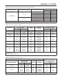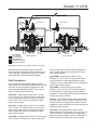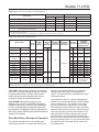
1
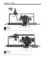
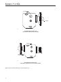
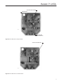
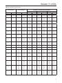
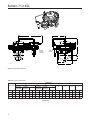
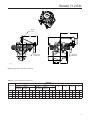
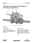
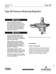
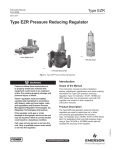
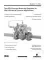
Bulletin 71.2:EZL
February 2015
Type EZL Pressure Reducing Regulator for
Low Differential Pressure Applications
¶ 290 psig / 20.0 bar Inlet/Outlet Rating
¶ Low Differential
¶ Bubble Tight Shutoff
¶ Absolutely No Atmospheric Bleed
¶ Full Usable Capacity
W8962
Figure 1. Type EZL Pressure Reducing Regulator
¶ Ease of Adjustment
¶ Common Body Platform
¶ Top Entry Design for
Ease of Maintenance
¶ Resistant to Aromatics
and Particle Erosion
D103092X012
¶ Precise Pressure Control
www.fisherregulators.com
Bulletin 71.2:EZL
Specifications
The Specifications section lists the specifications for Type EZL pressure reducing regulator. Factory specifications
for specific regulator constructions are stamped on the nameplate fastened to either the main actuator or the pilot
spring case.
Body Sizes, End Connection Styles and
Pressure Ratings(1)
See Table 1
Maximum Inlet and Outlet (Casing) Pressures(1)
290 psig / 20.0 bar
Maximum Emergency (Design Casing Pressure)(1)
290 psig / 20.0 bar
Maximum Operating Differential Pressure(1)
290 psid / 20.0 bar d
Minimum Differential Pressure(1)
TRIM, PERCENT
OF CAPACITY
100
80
50
30
MINIMUM DIFFERENTIAL FOR
FULL STROKE, psid / bar d
2 in. / DN 50
3 in. / DN 80
4 in. / DN 100
2.9 / 0.204
2.9 / 0.204
3.0 / 0.207
3.4 / 0.234
2.9 / 0.204
3.1 / 0.214
3.2 / 0.221
3.5 / 0.241
2.9 / 0.204
3.2 / 0.221
3.7 / 0.255
3.9 / 0.269
Outlet Pressure Ranges
See Table 2
Proportional Band Ranges
See Table 2
IEC Sizing Coefficients
See Table 6
Flow Coefficients
See Tables 7, 8, 9 and 10
Flow Capacities
See Tables 11 and 12
Pressure Registration
External
Temperature Capabilities(1)
Nitrile (NBR) Version: -20 to 180°F / -29 to 82°C
Fluorocarbon (FKM) Version: 0 to 180°F / -18 to 82°C
Options
• Pre-piped Pilot Supply
• Travel Indicator
• Integral Type OS2 Slam-shut Device
Construction Materials
Type EZL Main Valve
Main Body: Cast iron or WCC Steel
Intermediate Flange: Steel
Actuator Casings: Anodized Forged Aluminum
Inlet and Outlet Plates: Steel
Diaphragm: Nitrile (NBR) with PVC coating
O-ring: Nitrile (NBR) or Fluorocarbon (FKM)
Seat: Nitrile (NBR) or Fluorocarbon (FKM)
Type 6352, 6353, 6354L, 6354M or 6354H Pilot
Body, Body Plug, Spring Case and Closing Cap:
Aluminum (standard) or Stainless steel
Control Spring: Zinc-plated steel
Bellows Assembly: Nickel and stainless steel
Body Plug and Closing Cap Gaskets: Composition
Other Metal Trim Parts: Steel, Aluminum and/or
Stainless steel
Diaphragm:
Type 6352: Nitrile (NBR)
Type 6353: Nitrile (NBR) or Fluorocarbon (FKM)
6354 Series: Neoprene (CR) or Fluorocarbon (FKM)
O-rings and Soft Parts: Nitrile (NBR) (standard) or
Fluorocarbon (FKM) (high temperature)
61 Series Pilots
Body and Spring Case: Cast iron
Upper and Lower Diaphragm
Type 61L: Nitrile (NBR) or Fluorocarbon (FKM)
Type 61HP: Neoprene (CR) or Fluorocarbon (FKM)
Metal Trim Parts: Steel, Stainless steel, Cast iron,
Aluminum, Brass or Zinc
Gasketing: Neoprene (CR)
Elastomer Seat and O-ring: Nitrile (NBR) or
Fluorocarbon (FKM)
Types 161M and 161EBM Pilots
Body: Stainless steel
Spring Case: Stainless steel
Body Plug and Diaphragm Limiter: Stainless steel
Control Spring and Adjusting screw: Plated steel
Valve Plug, Diaphragm and O-ring: Nitrile (NBR)
or Fluorocarbon (FKM)
Pilot and Actuator Vents
Type Y602 vent assembly
Type 252 Pilot Supply Filter
Body: Aluminum or Stainless steel
Filter Cartridge: Polyethylene
O-ring: Nitrile (NBR)
Drain Valve or Pipe Plug: Stainless steel
Type P590 Pilot Supply Filter
Body and Filter Head: Aluminum or Brass
Filter Element: Cellulose
1. The pressure/temperature limits in this Bulletin and any applicable standard or code limitation should not be exceeded.
2
Bulletin 71.2:EZL
• Main Diaphragm—The main diaphragm is Nitrile
(NBR) reinforced with fabric coated with a PVC,
which protects and extends the service life of the
regulator in applications where liquids commonly
found in natural gas pipe lines tend to shorten
diaphragm life.
• Common Body Platform—The Type EZL uses the
same standard Fisher® E-Body as the Types EZH
and EZR pressure reducing regulators and
Types EZ, ES, ED and ET pressure reducing control
valves. This will allow easy conversion from one
product to another without the need to remove the
E-Body from the pipeline.
• Bubble Tight Shutoff—The Type EZL has a knifeedged, metal plug and a soft seat which provides
bubble tight shutoff for use in applications where
positive shutoff is required. For example: deadend systems.
• Absolutely No Atmospheric Bleed—The
Type EZL eliminates nuisance and wasteful bleed
gas to atmosphere by utilizing a pilot-operated
two-path control system, which bleeds 100% of the
gas to the downstream system while the regulator
is operating.
• High Turn Down Capability—The oversized
diaphragm and unique piloting system of the
Type EZL allows for a 100:1 turn down ratio, which
will provide superior pressure control in systems
with large variations in downstream flow demand.
• In-Line Maintenance—Top entry design reduces
maintenance time. Trim parts can be inspected,
cleaned and replaced without removing the body
from pipeline.
• Precise Pressure Control—The Type EZL
utilizes a wide range of pilots to provide stable and
accurate downstream pressure control regardless
of load changes or inlet pressure variations.
• Full Usable Capacity—Fisher regulators are
laboratory tested. 100% of the published flow
capacity can be used with confidence.
• O-ring Design—The Type EZL uses elastomer
O-rings, reducing maintenance and assembly time.
Introduction
Type EZL regulators are accurate pilot-operated,
pressure balanced and soft seated regulators. They
are designed for use in natural gas distribution
applications such as district regulating stations and
commercial/industrial meter sets. They provide low
differential, smooth, reliable operation, tight shutoff
and long life.
The Type EZL pressure reducing regulator includes a
pilot mounted on the Type EZL main valve for pressure
reducing, wide-open monitoring or working monitoring
applications. The Type EZL is also available with a
slam-shut device for overpressure or overpressure and
underpressure protection.
Principle of Operation
Single-Pilot Regulator (Figures 2 and 3)
The pilot-operated Type EZL uses inlet pressure as
the operating medium, which is reduced through pilot
operation to load the actuator diaphragm. Outlet or
downstream pressure opposes loading pressure in the
actuator and also opposes the pilot control spring.
When outlet pressure drops below the setting of the
pilot control spring, pilot control spring force on the pilot
diaphragm thus opens the pilot valve plug, providing
additional loading pressure to the actuator diaphragm.
This diaphragm loading pressure opens the main valve
plug, supplying the required flow to the downstream
system. Any excess loading pressure on the actuator
diaphragm escapes downstream through the bleed
restriction in the pilot.
When the gas demand in the downstream system
has been satisfied, the outlet pressure increases.
The increased pressure is transmitted through
the downstream control line and acts on the pilot
diaphragm. This pressure exceeds the pilot spring
setting and moves the diaphragm, closing the orifice.
The loading pressure acting on the main diaphragm
bleeds to the downstream system through a bleed
restriction in the pilot.
3
January 2008
Bulletin
71.2:EZL
Type
EZL with
6350 Series Pilot and
Type P590 Pilot Supply Filter
Type EZL
TYPE 6352 PILOT
P590 SERIES PILOT
SUPPLY FILTER
E0944
E0944
INLET PRESSURE
INLET PRESSURE
OUTLET PRESSURE
OUTLET PRESSURE
ATMOSPHERIC
PRESSURE
ATMOSPHERIC
PRESSURE
LOADING
PRESSURE
LOADING
PRESSURE
January 2008
TYPE EZL MAIN VALVE
Type EZL
Type EZL with Type 61L Pilot
Figure 2. Principle of Operation for the Type EZL with Type 6352 Pilot and Type P590 Pilot Supply Filter
P590 SERIES PILOT
SUPPLY FILTER
E0959
TYPE 61L PILOT
E0959
INLET PRESSURE
OUTLET
PRESSURE
INLET
PRESSURE
OUTLET
PRESSURE
ATMOSPHERIC
PRESSURE
LOADING
LOADING PRESSURE
PRESSURE
ATMOSPHERIC PRESSURE
TYPE EZL MAIN VALVE
Figure 3. Principle of Operation for the Type EZL with Type 61L Pilot and Type P590 Pilot Supply Filter
4
Bulletin 71.2:EZL
Table 1. Main Valve Body Sizes, End Connection Styles and Body Ratings
MAIN VALVE BODY SIZE
MAIN VALVE BODY MATERIAL
END CONNECTION STYLE
psig
bar
NPT(2) or SWE(2)
1500
103
CL150 RF
290
20.0
CL300 RF
750
51.7
CL600 RF or BWE
1500
103
NPT(2)
400
27.6
CL125 FF
200
13.8
CL250 RF
500
34.5
WCC Steel
2, 3 and 4 in. /
DN 50, 80 and 100
STRUCTURAL DESIGN RATING(1)
Cast Iron
1. Structural Design Rating is the rating for the main valve body. The Type EZL complete assembly is limited to 290 psig / 20.0 bar.
2. Only available in 2 in. / DN 50 body sizes.
Table 2. Outlet (Control) Pressure Ranges
OUTLET (CONTROL)
PRESSURE RANGE
PILOT TYPE
SPRING
COLOR
SPRING
PART NUMBER
APPROXIMATE
PROPORTIONAL BAND
psig
bar
psig
bar
6352
2 to 10
0.14 to 0.69
Black
14A9673X012
0.3
0.02
6353
3 to 40
35 to 125
0.21 to 2.8
2.41 to 8.6
Yellow
Red
1E392527022
1K748527202
0.5
1.0
0.03
0.07
6354L(1)
6354M(2)
6354H(2)
85 to 200
175 to 220
200 to 300
5.9 to 13.8
12.1 to 15.2
13.8 to 20.7(4)
Blue
Blue
Green
1L346127142
1L346127142
15A9258X012
3.0
3.0
5.0
0.2
0.2
0.3
61L
0.25 to 2
1 to 5
2 to 10
5 to 15
10 to 20
0.017 to 0.14
0.069 to 0.35
0.14 to 0.69
0.35 to 1.03
0.69 to 1.38
Red
Yellow
Blue
Brown
Green
1B886327022
1J857827022
1B886427022
1J857927142
1B886527022
0.15
0.2
0.3
0.5
0.7
0.01
0.01
0.02
0.03
0.05
61HP
15 to 45
35 to 100
100 to 300
1.03 to 3.10
2.41 to 6.90
6.90 to 20.7(4)
Yellow
Blue
Red
1E392527022
1D387227022
1D465127142
1.0
1.5
3.0
0.07
0.1
0.2
161M(3)
5 to 15
10 to 125
120 to 300
0.34 to 1.03
0.69 to 8.6
8.3 to 20.7(4)
Yellow
Red
Green
1E392527022
1K748527202
15A9258X012
0.5
2.0
5.0
0.03
0.14
0.3
161EBM(3)
5 to 15
10 to 40
30 to 75
70 to 140
130 to 200
200 to 350
0.34 to 1.03
0.69 to 2.8
2.07 to 5.17
4.83 to 9.65
8.96 to 13.8
13.8 to 24.1(4)
White
Yellow
Black
Green
Blue
Red
17B1260X012
17B1262X012
17B1259X012
17B1261X012
17B1263X012
17B1264X012
0.3
0.5
1.0
2.0
4.0
5.0
0.02
0.03
0.07
0.14
0.28
0.3
1. Without diaphragm limiter.
2. With diaphragm limiter.
3. Monitoring pilot for working monitors.
4. Operating range is limited to maximum pressure.
Table 3. Working Monitor Pilot Performance
MONITORING PILOT INFORMATION
MONITOR PILOT FOR WORKING
MONITOR APPLICATION
OUTLET (CONTROL)
PRESSURE RANGE
SPRING
COLOR
SPRING
PART NUMBER
MINIMUM PRESSURE OVER
NORMAL OUTLET PRESSURE AT
WHICH WORKING MONITOR PILOT
CAN BE SET
psig
bar
psid
bar d
Type 161M
5 to 15
10 to 125
120 to 300
0.34 to 1.03
0.69 to 8.6
8.3 to 20.7(1)
Yellow
Red
Green
1E392527022
1K748527202
15A9258X012
3.0
4.0
5.0
0.2
0.28
0.3
Type 161EBM
5 to 15
10 to 40
30 to 75
70 to 140
130 to 200
200 to 350
0.34 to 1.03
0.69 to 2.8
2.07 to 5.17
4.83 to 9.65
8.96 to 13.8
13.8 to 24.1(1)
White
Yellow
Black
Green
Blue
Red
17B1260X012
17B1262X012
17B1259X012
17B1261X012
17B1263X012
17B1264X012
3.0
3.0
3.0
4.0
5.0
5.0
0.2
0.2
0.2
0.28
0.3
0.3
1. Operating range is limited to maximum pressure.
5
Type EZL
Bulletin 71.2:EZL
January 2008
Type EZL Upstream or Downstream Wide-Open Monitor
TYPE 67C PILOT
SUPPLY REGULATOR
P590 SERIES
PILOT SUPPLY
FILTER
TYPE 6352 PILOT
TYPE 6352 PILOT
E0948
P590 SERIES PILOT
SUPPLY FILTER
E0948
INLET
PRESSURE
INLET
PRESSURE
OUTLET
PRESSURE
OUTLET
PRESSURE
LOADING
PRESSURE
LOADING
PRESSURE
INTERMEDIATE
INTERMEDIATEPRESSURE
PRESSURE
ATMOSPHERIC PRESSURE
TYPE EZL MAIN VALVE
TYPE EZL MAIN VALVE
ATMOSPHERIC PRESSURE
Figure 4. Wide-Open Monitoring System Operational Schematic
Monitoring Systems
Monitoring regulation is overpressure protection by
containment, therefore, there is no relief valve to vent
to the atmosphere. When the working regulator fails
to control the pressure, a monitor regulator installed
in series, which has been sensing the downstream
and control pressure, goes into operation to maintain
the downstream pressure at a slightly higher than
normal pressure. During an overpressure situation,
monitoring keeps the customer on line. Also, testing is
relatively easy and safe. To perform a periodic test on
a monitoring regulator, increase the outlet set pressure
of the working regulator and watch the outlet pressure
to determine if the monitoring regulator takes over at
the appropriate outlet pressure.
Wide-Open Monitoring Systems (Figure 4)
There are two types of wide-open monitoring systems:
upstream and downstream. The difference between
upstream and downstream monitoring is that the
functions of the regulators are reversed. Systems can
be changed from upstream to downstream monitoring,
and vice-versa, by simply reversing the setpoints
of the two regulators. The decision to use either an
upstream or downstream monitoring system is largely
a matter of personal preference or company policy.
6
In normal operation of a wide-open configuration,
the working regulator controls the system’s outlet
pressure. With a higher outlet pressure setting, the
monitor regulator senses a pressure lower than its
setpoint and tries to increase outlet pressure by going
wide-open. If the working regulator fails, the monitoring
regulator assumes control and holds the outlet
pressure at its outlet pressure setting.
Working Monitoring Regulators (Figure 5)
In a working monitoring system, the upstream
regulator requires two pilots and it is always the
monitoring regulator. The additional pilot permits
the monitoring regulator to act as a series regulator
to control an intermediate pressure during normal
operation. In this way, both units are always operating
and can be easily checked for proper operation.
In normal operation, the working regulator controls
the outlet pressure of the system. The monitoring
regulator’s working pilot controls the intermediate
pressure and the monitoring pilot senses the system’s
outlet pressure. If the working regulator fails, the
monitoring pilot will sense the increase in outlet
pressure and take control.
Type EZL
Bulletin 71.2:EZL
January 2008
TYPE 161EBM
MONITOR PILOT
P590 SERIES
PILOT SUPPLY
FILTER
TYPE 6352 PILOT
TYPE 6352 PILOT
E0962
P590 SERIES PILOT
SUPPLY FILTER
E0946
INLET PRESSURE
INLET PRESSURE
OUTLET
PRESSURE
TYPE EZL MAIN VALVE
LOADING
PRESSURE
OUTLET PRESSURE
INTERMEDIATE
PRESSURE
LOADING PRESSURE
ATMOSPHERIC PRESSURE
TYPE EZL MAIN VALVE
INTERMEDIATE PRESSURE
ATMOSPHERIC PRESSURE
Figure 5. Working Monitoring System Operational Schematic
Working monitor installations require a Type EZL
main valve with a working pilot and a monitoring pilot
for the upstream regulator and a Type EZL with the
appropriate pilot for the downstream regulator.
Pilot Descriptions
The Type EZL pressure reducing regulator includes
either a 6350 or 61 Series pilot mounted on the Type EZL
main valve for pressure-reducing application or wideopen monitoring applications and 161 Series monitor
pilots for working monitoring systems.
Type 6352—Outlet pressure range of 2 to 10 psig /
0.14 to 0.69 bar. The Type 6352 can be used as the
pilot on single stage pressure reducing regulators or
as the monitor pilot or as the working pilot in wideopen monitor systems.
Type 6353—Outlet pressure range of 3 to 125 psig /
0.21 to 8.6 bar. The Type 6353 can be used as the
pilot on single stage pressure reducing regulators or
as the monitor pilot or as the working pilot in wideopen monitor systems.
Type 6354L—Outlet pressure range of 85 to 200 psig /
5.9 to 13.8 bar. The Type 6354L can be used as the
pilot on single stage pressure reducing regulators or
as the monitor pilot or as the working pilot in wideopen monitor systems.
Type 6354M—Outlet pressure range of 175 to
220 psig / 12.1 to 15.2 bar. The Type 6354M can be
used as the pilot on single stage pressure reducing
regulators or as the monitor pilot or as the working pilot
in wide-open monitor systems.
Type 6354H—Outlet pressure range of 200 to
290 psig / 13.8 to 20.0 bar. The Type 6354H can be
used as the pilot on single stage pressure reducing
regulators or as the monitor pilot or as the working pilot
in wide-open monitor systems.
Type 61L—Low pressure pilot for outlet pressure range
of 0.25 to 20 psig / 0.02 to 1.38 bar. The Type 61L can
be used as the pilot on single stage pressure reducing
regulators or as the monitor pilot or as the working pilot in
wide-open monitor systems.
Type 61HP—Extra high pressure pilot for outlet
pressure range of 15 to 290 psig / 1.03 to 20.0 bar. The
Type 61HP can be used as the pilot on single stage
pressure reducing regulators or as the monitor pilot or
as the working pilot in wide-open monitor systems.
7
Bulletin 71.2:EZL
EQUALIZER BYPASS
VALVE PLUG
VALVE PLUG DISK
MANOMETRIC DEVICE
INLET PRESSURE
OUTLET PRESSURE
ATMOSPHERIC PRESSURE
LOADING PRESSURE
Figure 6. Type EZLOSX Operational Schematic
8
15 mm
MECHANISM BOX
EVENT
E0971
35 mm
50 mm
COURSE CLAPET
MANOMETRIC DEVICE STEM
Bulletin 71.2:EZL
Table 4. Applications and Construction Guide (See Figure 7)
MECHANISM BOX REQUIRED
APPLICATION
MANOMETRIC SENSING DEVICE REQUIRED
Type BM1
Type BM2
Type BMS1
Type BMS2
Overpressure Shutoff (OPSO)
Yes
No
Yes
No
Underpressure Shutoff (UPSO)
Yes
No
Yes
No
Overpressure Shutoff (OPSO) and Underpressure Shutoff (UPSO)
Yes
No
Yes(1)
No
Yes
Yes(1)
Overpressure Shutoff (OPSO) and Underpressure Shutoff (UPSO)
No
Yes
Yes(2)
Overpressure Shutoff (OPSO), Overpressure Shutoff (OPSO)
and Underpressure Shutoff (UPSO)
No
Yes
Yes(2)
1. When using one manometric sensing device (Type BMS1 or BMS2) for both overpressure and underpressure shutoff, make sure that the difference between set pressures falls within
the maximum range shown in Table 5.
2. When using two manometric sensing devices (Type BMS1 and a Type BMS2), the Type BMS1 can only be used for high trip.
Table 5. Manometric Device Specifications(1)
SPRING RANGE
SPRING
COLOR
psig
bar
4.02 to
14.1 in. w.c.
10 to 35 mbar
Purple
9.97 to
33.2 in. w.c.
25 to 83 mbar
18 in. w.c. to
2.0 psig
SPRING
PART
NUMBER
MAXIMUM
SENSING
INLET
PRESSURE
psig
bar
psig
bar
T14232T0012
0.058
0.004
0.145
0.010
Orange
T14233T0012
0.073
0.005
0.363
0.025
45 mbar to
0.14 bar
Red
T14234T0012
0.145
0.010
0.725
0.050
1.0 to 3.5
0.069 to 0.241
Yellow
T14235T0012
0.203
0.014
0.870
0.060
1.7 to 5.6
0.117 to 0.386
Green
T14236T0012
0.261
0.018
2.18
0.150
2 to 11
0.140 to 0.758
Gray
T14238T0012
0.725
0.050
5.08
0.350
4 to 19
0.276 to 1.3
Brown
T14239T0012
1.16
0.080
8.70
0.600
7 to 33
0.483 to 2.3
Black
T14240T0012
2.47
0.170
16.0
1.10
15 to 75
1.0 to 5.2
Blue
T14237T0012
5.08
0.350
36.3
2.50
31 to 161
2.1 to 11.1
Brown
T14239T0012
10.2
0.703
79.8
5.50
59 to 235
4.1 to 16.2
Black
T14240T0012
23.2
1.600
145
10.0
235 to 290
16.2 to 20.0
psig
MAXIMUM
DIFFERENCE
SETPOINT
MANOMETRIC MANOMETRIC
BETWEEN
TOLERANCE(1)
SENSING
SENSING
OVERPRESSURE AND
DEVICE TYPE DEVICE STYLE
UNDERPRESSURE(2)
Brown
T14239T0012
75
bar
5
162
Diaphragm
235
1470
16
100
71
27
Piston
43.5
3.00
Requires use of a
Type BMS1 and a
Type BMS2
1. Minimum suggested difference between slam-shut set pressure and normal operating pressure of the system.
2. Maximum difference between overpressure and underpressure when using one manometric device (Type BMS1) with tripping hook. For underpressure and overpressure points greater
than this maximum number, use a second manometric device (Type BMS2) for underpressure protection.
Type 161M—Outlet pressure range from 5 to 290 psig /
0.34 to 20.0 bar. A static sensing (control) line is isolated
from pilot bleed (exhaust). The Type 161M is used in
working monitor and other application that require a
sensing line isolated from pilot bleed (exhaust).
Type 161EBM—Outlet pressure range from 5 to
290 psig / 0.34 to 20.0 bar. The pilot bleed (exhaust) is
isolated from the sense (control) line. Type 161EBM pilot
is used in monitoring systems requiring an isolated pilot
bleed (exhaust). For applications that have high pressure
drops, using a Type 161EBM monitor pilot will increase the
accuracy of the regulator.
Slam-Shut Device Principle of Operation
The optional slam-shut device can provide either
overpressure (OPSO) or overpressure (OPSO) and
underpressure (UPSO) protection by completely
shutting off the flow of gas to the downstream
system. The slam-shut has a mechanism box and a
manometric device.
The manometric device is a spring and diaphragm
actuator. Its movement activates the detection stage
of the mechanism box. The shutoff is a two stage
process, the detection stage and the power stage.
This separation between detection stage and power
stage provides maximum precision, alleviating many
false trips caused by environmental vibrations. The
slam-shut device includes a bypass valve that will
allow pressure to be equalized when resetting the
device. Once the slam-shut device has been tripped,
it must be manually reset. For more information about
the Type EZL with a slam-shut device, contact the
local Sales Office.
9
Bulletin 71.2:EZL
TYPE BM1
FRANCEL
TYPE BMS1
FRANCEL
E0564
MECHANISM BOX (TYPE BM1) WITH
1 MANOMETRIC SENSING DEVICE (TYPE BMS1)
TYPE BM2
FRANCEL
TYPE BMS1
(RIGHT SIDE)
FRANCEL
TYPE BMS2
(LEFT SIDE)
E0565
MECHANISM BOX (TYPE BM2) WITH
2 MANOMETRIC SENSING DEVICES (TYPES BMS1 AND BMS2)
Figure 7. Types of Installation (Mounting on Horizontal Pipeline Only)
10
Bulletin 71.2:EZL
FIRST STAGE RESET PIN (RED)
MECHANISM BOX
W8128
SECOND STAGE
RELEASING SHAFT
Figure 8. Slam-Shut Device in Open Position
SETPOINT ADJUSTMENT RING
W8129
Figure 9. Slam-Shut Device in Closed Position
11
Bulletin 71.2:EZL
Table 6. IEC Sizing Coefficients
MAIN VALVE
BODY SIZE
In.
DN
2
50
3
80
4
100
TRIM, PERCENT
OF CAPACITY
100
80
50
30
100
80
50
30
100
80
50
30
LINE SIZE EQUALS BODY SIZE
XT
FD
XT
FD
0.829
0.723
0.616
0.714
0.710
0.685
0.788
0.770
0.672
0.784
0.779
0.770
0.61
0.58
0.50
0.39
0.61
0.55
0.42
0.34
0.72
0.57
0.45
0.36
0.766
0.740
0.723
0.652
0.660
0.676
0.706
0.660
0.714
0.600
0.736
0.871
0.60
0.55
0.46
0.38
0.60
0.55
0.43
0.35
0.70
0.61
0.45
0.35
Installation
The Type EZL may be installed in any position, but
is normally installed in a horizontal pipeline with
the pilot or pilots above the body. See Figure 10 for
typical piping installation.
Capacity Information
Note
Type EZL flow capacities are laboratory
verified; therefore, they may be sized for
100% flow using capacities as shown in
Table 11. It is not necessary to reduce
published capacities.
Tables 11 and 12 show the natural gas regulating
capacities of the Type EZL regulator at selected inlet
pressures and outlet pressure settings. Flows are in
thousands of SCFH at 60°F and 14.7 psia (and in
thousands of Nm³/h at 0°C and 1.01325 bar) of 0.6
specific gravity natural gas. To determine equivalent
capacities for air, propane, butane or nitrogen, multiply the
capacity by the following appropriate conversion factor:
0.775 for air, 0.628 for propane, 0.548 for butane or 0.789
for nitrogen. For gases of other specific gravities, multiply
the given capacity by 0.775 and divide by the square
root of the appropriate specific gravity. Then, if capacity
is desired in normal cubic meters per hour at 0°C and
1.01325 bar, multiply SCFH by 0.0268.
To find approximate regulating capacities at pressure
settings not given in Tables 11 and 12 or to find
12
2:1 LINE SIZE TO BODY SIZE
PIPING
FL
0.89
wide-open flow capacities for relief sizing at any inlet
pressure, perform one of the following procedures.
Then, if necessary, convert using the factors
provided above.
Critical Pressure Drops
For critical pressure drops (absolute outlet pressure
equal to or less than one-half of absolute inlet
pressure), use the following formula:
Q = (P1)(Cg)(1.29)
Non-Critical Pressure Drops
For pressure drops lower than critical (absolute
outlet pressure greater than one-half of absolute
inlet pressure).
Q
=
520
CgP1SIN
GT
)
3417
C1
P
P1
)
DEG
where,
Q = gas flow rate, SCFH
P1 = absolute inlet pressure, psia (P1 gauge + 14.7)
Cg = regulating or wide-open gas sizing coefficient
G = gas specific gravity of the gas
T = absolute temperature of gas at inlet, °Rankine
C1 = flow coefficient
P = pressure drop across the regulator, psi
Bulletin 71.2:EZL
Table 7. Type EZL Main Valve Regulating Flow Coefficients
MAIN VALVE
BODY SIZE
In.
DN
2
50
3
80
4
100
TRIM, PERCENT
OF CAPACITY
100
80
50
30
100
80
50
30
100
80
50
30
LINE SIZE EQUALS BODY SIZE
2:1 LINE SIZE TO BODY SIZE PIPING
Cg
Cv
C1
Cg
Cv
C1
2290
1914
1290
858
4800
3950
2440
1560
6560
4550
2740
1760
63.2
56.7
41.4
25.5
144
120
69.2
44.8
200
129
78.2
50.5
36.2
33.8
31.2
33.6
33.5
32.9
35.3
34.9
32.6
35.2
35.1
34.9
2140
1760
1230
800
4580
3930
2420
1570
6440
4500
2750
1760
61.5
51.5
36.4
24.9
142
120
72.5
48.7
192
146
80.7
47.4
34.8
34.2
33.8
32.1
32.3
32.7
33.4
32.3
33.6
30.8
34.1
37.1
Table 8. Type EZL Main Valve Wide-Open Flow Coefficients
MAIN VALVE
BODY SIZE
In.
DN
2
50
3
80
4
100
TRIM, PERCENT
OF CAPACITY
100
80
50
30
100
80
50
30
100
80
50
30
LINE SIZE EQUALS BODY SIZE
2:1 LINE SIZE TO BODY SIZE PIPING
Cg
Cv
C1
Cg
Cv
C1
2360
1970
1330
884
4940
4060
2510
1610
6760
4690
2830
1820
65.0
58.4
42.6
26.3
148
123
71.3
46.1
208
133
80.5
52.0
37.3
34.8
32.1
34.7
34.5
33.9
36.3
35.9
33.5
36.3
35.2
36.0
2200
1810
1270
820
4710
4050
2500
1620
6630
4630
2830
1810
63.3
53.0
37.5
25.7
146
124
74.7
50.1
198
151
83.1
48.7
35.8
35.2
34.8
33.1
33.3
33.7
34.5
33.3
34.6
31.7
35.1
38.2
Table 9. Type EZLOSX Main Valve Regulating Flow Coefficients
MAIN VALVE
BODY SIZE
In.
DN
2
50
3
80
4
100
TRIM, PERCENT
OF CAPACITY
100
80
50
30
100
80
50
30
100
80
50
30
LINE SIZE EQUALS BODY SIZE
2:1 LINE SIZE TO BODY SIZE PIPING
Cg
Cv
C1
Cg
Cv
C1
2210
1890
1270
855
4610
4060
2600
1610
6280
4470
2740
1770
65.7
58.6
43.2
26.6
134
117
75.3
46.5
194
145
88.3
61.0
33.6
32.3
29.5
32.1
34.5
34.5
34.5
34.6
32.4
30.9
31.0
29.0
2058
1790
1250
872
4390
3900
2420
1580
6160
4380
2700
1780
64.6
56.6
40.3
28.5
134
118
72.1
49.2
194
141
86.3
65.8
31.9
31.6
31.1
30.6
32.9
33.1
33.6
32.1
31.7
31.1
31.2
27.1
Table 10. Type EZLOSX Main Valve Wide-Open Flow Coefficients
MAIN VALVE
BODY SIZE
In.
DN
2
50
3
80
4
100
TRIM, PERCENT
OF CAPACITY
100
80
50
30
100
80
50
30
100
80
50
30
LINE SIZE EQUALS BODY SIZE
2:1 LINE SIZE TO BODY SIZE PIPING
Cg
Cv
C1
Cg
Cv
C1
2280
1950
1310
881
4750
4180
2680
1660
6470
4600
2820
1820
67.7
60.4
44.5
27.4
138
121
77.6
47.9
200
149
91.0
62.8
34.6
33.2
30.4
33.1
35.5
35.6
35.5
35.7
33.4
31.8
31.9
29.8
2120
1840
1290
898
4520
4020
2490
1620
6340
4500
2780
1840
66.5
58.3
41.5
29.4
138
121
74.2
50.6
200
145
88.9
67.8
32.8
32.6
32.0
31.5
33.9
34.1
34.6
33.0
32.7
32.1
32.2
27.9
13
Bulletin 71.2:EZL
Table 11. Capacities for Type EZL
INLET PRESSURE
OUTLET PRESSURE
CAPACITIES IN THOUSANDS OF SCFH / Nm3/h OF 0.6 SPECIFIC GRAVITY NATURAL
GAS USING 1:1 LINE SIZE TO BODY SIZE PIPING
2 IN. / DN 50 BODY
4 IN. / DN 100 BODY
bar
psig
bar
SCFH
Nm3/h
SCFH
Nm3/h
SCFH
Nm3/h
4
0.3
0.25
0.02
37
1.00
83
2.22
116
3.10
5
0.3
0.25
1
2
0.02
0.07
0.14
42
39
35
1.13
1.06
0.94
94
88
78
2.51
2.35
2.10
130
122
109
3.50
3.28
2.93
10
0.7
0.25
3
5
7
0.02
0.21
0.34
0.48
63
56
49
40
1.68
1.51
1.32
1.06
138
124
110
89
3.69
3.33
2.95
2.39
191
173
153
124
5.12
4.64
4.11
3.34
15
1.0
1
4
8
12
0.07
0.28
0.55
0.83
79
74
63
44
2.13
1.98
1.69
1.18
173
162
140
99
4.64
4.36
3.75
2.65
239
225
195
138
6.41
6.05
5.23
3.71
20
1.4
1
10
15
17
0.07
0.69
1.03
1.17
96
79
60
48
2.58
2.13
1.61
1.28
208
175
134
107
5.58
4.71
3.61
2.88
287
244
188
150
7.70
6.55
5.04
4.04
30
2.1
4
15
20
25
0.28
1.03
1.38
1.72
126
108
93
69
3.37
2.89
2.49
1.86
271
237
206
155
7.26
6.37
5.54
4.17
372
330
288
217
10.0
8.86
7.73
5.83
40
2.8
9
20
30
35
0.62
1.38
2.07
2.41
153
136
105
77
4.10
3.64
2.81
2.07
330
298
234
174
8.85
8.00
6.27
4.66
454
414
326
243
12.2
11.1
8.76
6.53
3.4
13
20
30
40
45
0.90
1.38
2.07
2.76
3.10
181
172
152
115
85
4.86
4.62
4.07
3.10
2.27
391
375
335
258
190
10.5
10.1
8.99
6.93
5.11
538
519
466
361
267
14.4
13.9
12.5
9.68
7.16
60
4.1
17
25
35
45
55
1.17
1.72
2.41
3.10
3.79
209
199
180
149
91
5.62
5.35
4.83
3.99
2.45
451
434
397
331
206
12.1
11.7
10.6
8.89
5.52
622
600
551
462
288
16.7
16.1
14.8
12.4
7.73
75
5.2
24
50
60
70
1.65
3.45
4.14
4.83
251
202
165
100
6.73
5.44
4.44
2.70
541
448
370
227
14.5
12.0
9.92
6.08
745
624
516
318
20.0
16.8
13.9
8.53
100
6.9
35
60
75
2.41
4.14
5.17
320
280
236
8.60
7.52
6.33
691
617
525
18.6
16.6
14.1
953
856
732
25.6
23.0
19.6
125
8.6
46
75
3.17
5.17
390
344
10.5
9.23
842
757
22.6
20.3
1160
1051
31.1
28.2
150
10
57
75
100
125
3.93
5.17
6.89
8.62
460
436
383
291
12.3
11.7
10.3
7.82
992
951
847
652
26.6
25.5
22.8
17.5
1367
1316
1179
911
36.7
35.3
31.6
24.5
175
12
68
75
100
125
150
4.69
5.17
6.89
8.62
10.3
530
522
482
419
316
14.2
14.0
12.9
11.3
8.47
1143
1129
1057
930
707
30.7
30.3
28.4
25.0
19.0
1574
1558
1465
1296
989
42.3
41.8
39.3
34.8
26.6
200
14
75
100
125
150
175
5.17
6.89
8.62
10.3
12.1
603
572
525
453
338
16.2
15.4
14.1
12.2
9.07
1300
1246
1155
1007
759
34.9
33.5
31.0
27.0
20.4
1789
1723
1603
1404
1062
48.0
46.3
43.0
37.7
28.5
16
75
100
125
150
175
200
5.17
6.89
8.62
10.3
12.1
13.8
683
657
619
564
484
359
18.3
17.6
16.6
15.1
13.0
9.64
1465
1424
1355
1246
1078
807
39.3
38.2
36.4
33.4
28.9
21.7
2013
1966
1877
1732
1504
1130
54.0
52.8
50.4
46.5
40.4
30.3
17
75
125
150
175
200
225
5.17
8.62
10.3
12.1
13.8
15.5
761
708
663
601
513
379
20.4
19.0
17.8
16.1
13.8
10.2
1627
1541
1456
1331
1145
853
43.7
41.4
39.1
35.7
30.7
22.9
2232
2131
2021
1853
1599
1194
59.9
57.2
54.2
49.7
42.9
32.1
20
75
125
150
175
200
225
5.17
8.62
10.3
12.1
13.8
15.5
869
826
791
744
681
595
23.3
22.2
21.2
20.0
18.3
16.0
1850
1789
1726
1635
1507
1327
49.7
48.0
46.3
43.9
40.5
35.6
2534
2467
2388
2270
2098
1852
68.0
66.2
64.1
60.9
56.3
49.7
50
225
250
285
14
3 IN. / DN 80 BODY
psig
Bulletin 71.2:EZL
Table 12. Capacities for Type EZLOSX
INLET PRESSURE
OUTLET PRESSURE
CAPACITIES IN THOUSANDS OF SCFH / Nm3/h OF 0.6 SPECIFIC GRAVITY NATURAL
GAS USING 1:1 LINE SIZE TO BODY SIZE PIPING
2 IN. / DN 50 BODY
3 IN. / DN 80 BODY
4 IN. / DN 100 BODY
psig
bar
psig
bar
SCFH
Nm3/h
SCFH
Nm3/h
SCFH
Nm3/h
4
0.3
0.25
0.02
38
1.02
78
2.09
111
2.98
5
0.3
0.25
1
2
0.02
0.07
0.14
43
40
36
1.15
1.08
0.96
88
82
73
2.36
2.21
1.96
125
118
105
3.37
3.16
2.82
10
0.7
0.25
3
5
7
0.02
0.21
0.34
0.48
63
57
50
41
1.70
1.53
1.35
1.10
130
117
103
83
3.49
3.14
2.77
2.23
183
166
147
120
4.92
4.46
3.96
3.21
15
1.0
1
4
8
12
0.07
0.28
0.55
0.83
79
75
64
45
2.13
2.00
1.72
1.22
164
153
131
92
4.40
4.12
3.53
2.48
229
217
188
133
6.16
5.81
5.03
3.57
20
1.4
1
10
15
17
0.07
0.69
1.03
1.17
96
81
62
49
2.57
2.16
1.66
1.32
198
165
126
100
5.30
4.43
3.38
2.70
275
235
181
145
7.38
6.30
4.85
3.89
30
2.1
4
15
20
25
0.28
1.03
1.38
1.72
124
109
95
71
3.34
2.93
2.55
1.91
257
224
194
145
6.91
6.01
5.21
3.90
357
317
277
209
9.58
8.51
7.43
5.61
40
2.8
9
20
30
35
0.62
1.38
2.07
2.41
152
137
107
80
4.07
3.68
2.88
2.14
314
281
219
162
8.42
7.55
5.88
4.36
436
398
314
234
11.7
10.7
8.42
6.28
3.4
13
20
30
40
45
0.90
1.38
2.07
2.76
3.10
180
172
154
119
87
4.82
4.63
4.13
3.18
2.35
371
355
315
242
178
9.97
9.54
8.47
6.49
4.77
516
498
448
347
257
13.8
13.4
12.0
9.32
6.89
60
4.1
17
25
35
45
55
1.17
1.72
2.41
3.10
3.79
208
200
182
152
94
5.57
5.36
4.89
4.08
2.53
429
411
374
311
192
11.5
11.0
10.0
8.34
5.16
596
576
529
444
277
16.0
15.5
14.2
11.9
7.45
75
5.2
24
50
60
70
1.65
3.45
4.14
4.83
249
206
170
104
6.68
5.53
4.56
2.79
514
422
346
212
13.8
11.3
9.30
5.68
715
600
497
306
19.2
16.1
13.3
8.21
100
6.9
35
60
75
2.41
4.14
5.17
318
283
241
8.54
7.61
6.47
657
582
493
17.7
15.6
13.2
913
823
704
24.5
22.1
18.9
125
8.6
46
75
3.17
5.17
387
348
10.4
9.34
801
714
21.5
19.2
1112
1009
29.9
27.1
150
10
57
75
100
125
3.93
5.17
6.89
8.62
456
437
389
299
12.3
11.7
10.5
8.04
944
901
798
611
25.3
24.2
21.4
16.4
1311
1263
1133
877
35.2
33.9
30.4
23.5
175
12
68
75
100
125
150
4.69
5.17
6.89
8.62
10.3
526
519
486
427
325
14.1
13.9
13.0
11.5
8.72
1087
1072
999
875
662
29.2
28.8
26.8
23.5
17.8
1510
1495
1407
1246
952
40.5
40.1
37.8
33.4
25.6
200
14
75
100
125
150
175
5.17
6.89
8.62
10.3
12.1
598
573
531
462
348
16.1
15.4
14.2
12.4
9.35
1237
1180
1089
946
710
33.2
31.7
29.2
25.4
19.1
1715
1654
1540
1350
1022
46.0
44.4
41.4
36.2
27.4
16
75
100
125
150
175
200
5.17
6.89
8.62
10.3
12.1
13.8
674
655
623
572
495
371
18.1
17.6
16.7
15.4
13.3
10.0
1396
1352
1281
1173
1012
755
37.5
36.3
34.4
31.5
27.2
20.3
1929
1885
1802
1664
1447
1088
51.8
50.6
48.4
44.7
38.8
29.2
17
75
125
150
175
200
225
5.17
8.62
10.3
12.1
13.8
15.5
749
709
669
612
526
392
20.1
19.0
18.0
16.4
14.1
10.5
1553
1460
1375
1253
1075
798
41.7
39.2
36.9
33.6
28.8
21.4
2139
2045
1941
1781
1538
1149
57.4
54.9
52.1
47.8
41.3
30.9
20
75
125
150
175
200
225
5.17
8.62
10.3
12.1
13.8
15.5
851
823
794
752
693
609
22.9
22.1
21.3
20.2
18.6
16.4
1769
1699
1634
1544
1419
1245
47.5
45.6
43.9
41.4
38.1
33.4
2427
2366
2293
2180
2017
1781
65.2
63.5
61.5
58.5
54.1
47.8
50
225
250
285
15
Bulletin 71.2:EZL
M
N
D
TYPE 61L,
61LD OR
61E PILOT
TYPE 252
FILTER
G
B
A
GE11539_B
Figure 10. Type EZL Dimensions
Table 13. Type EZL Dimensions
DIMENSION
BODY SIZE
A
CL125 FF,
CL150 RF
B
CL250 RF,
CL300 RF
CL600 RF
CL125 FF,
CL150 RF
CL250 RF,
CL300 RF
G
M
N
In.
DN
In.
mm
In.
mm
In.
mm
In.
mm
In.
mm
In.
mm
In.
mm
In.
mm
In.
mm
In.
mm
2
50
10.00
254
10.50
267
11.25
286
5.00
127
5.25
133
5.63
143
12.50
317
3.06
78
16.25
413
8.66
220
3
80
11.75
298
12.50
317
13.25
337
5.88
149
6.25
159
6.63
168
15.49
393
3.81
97
17.58
447
9.99
254
4
100
13.90
353
14.50
368
15.50
394
6.90
175
7.20
183
7.80
198
16.67
423
5.10
130
17.58
447
9.99
254
- continued -
16
D
CL600 RF
Bulletin 71.2:EZL
TYPE 252
FILTER
N
M
D
TYPE 6352, 6353
OR 6354 PILOT
TYPE 161M OR
161EBM PILOT
G
B
A
GE12413_B
Figure 10. Type EZL Dimensions (continued)
Table 13. Type EZL Dimensions (continued)
DIMENSION
BODY SIZE
A
CL125 FF,
CL150 RF
B
CL250 RF,
CL300 RF
CL600 RF
CL125 FF,
CL150 RF
CL250 RF,
CL300 RF
D
CL600 RF
G
M
N
In.
DN
In.
mm
In.
mm
In.
mm
In.
mm
In.
mm
In.
mm
In.
mm
In.
mm
In.
mm
In.
mm
2
50
10.00
254
10.50
267
11.25
286
5.00
127
5.25
133
5.63
143
13.53
344
3.06
78
10.50
267
12.50
317
3
80
11.75
298
12.50
317
13.25
337
5.88
149
6.25
159
6.63
168
16.52
420
3.81
97
11.83
300
14.13
359
4
100
13.90
353
14.50
368
15.50
394
6.90
175
7.20
183
7.80
198
19.03
483
5.10
130
11.83
300
14.13
359
17
Bulletin 71.2:EZL
H
D
M
N
GE24229_A
0.98 IN. / 25 mm
MECHANISM
BOX REMOVAL
CLEARANCE
Figure 11. Type EZLOSX Dimensions
Table 14. Type EZLOSX Dimensions
DIMENSION WITH SLAM-SHUT
BODY SIZE
D
M(1)
H
N
Diaphragm
Piston
Diaphragm
Piston
Bellow
In.
DN
In.
mm
In.
mm
In.
mm
In.
mm
In.
mm
In.
mm
In.
mm
2
50
13.0
330
10.4
264
6.38
162
2.80
71
6.89
175
8.03
204
8.78
223
3
80
14.34
364
11.78
299
6.38
162
2.80
71
6.89
175
8.03
204
8.78
223
4
100
15.64
397
13.09
332
6.38
162
2.80
71
6.89
175
8.03
204
8.78
223
1. Type 71 BMS with a diaphragm has an M dimension of 2.80 in. / 71 mm.
Table 15. Shipping Weights
APPROXIMATE SHIPPING WEIGHT
BODY SIZE
18
NPT
SWE
kg
Lbs
41
90
CL150 RF
In.
DN
Lbs
kg
2
50
90
3
80
----
----
4
100
----
----
201
41
CL300 RF
CL600 RF
SCH 40
Lbs
kg
Lbs
kg
Lbs
kg
Lbs
97
44
107
49
111
50
90
172
78
182
83
186
84
----
91
225
102
270
122
----
Actuator Only
kg
Lbs
kg
41
55
25
80
36
85
39
Bulletin 71.2:EZL
Ordering Guide
Type 161M
5 to 15 psig / 0.35 to 1.03 bar, Yellow***
10 to 125 psig / 0.69 to 8.6 bar, Red***
120 to 300 psig / 8.3 to 20.7 bar, Green(1)***
Body Size (Select One)
2 in. / DN 50 Body***
3 in. / DN 80 Body***
4 in. / DN 100 Body***
Body Material and End Connection Style (Select One)
WCC Steel
Cast Iron
NPT (2 in. only)*** NPT (2 in. only)***
CL150 RF*** CL125 FF***
CL300 RF*** CL250 RF***
CL600 RF***
BWE
(Indicate Schedule 40 or 80)**
SWE**
Main Valve Seat Material (Select One)
Nitrile (NBR) (standard)***
Fluorocarbon (FKM)***
Outlet Pressure Range (Select One)
Type 61L
0.25 to 2 psig / 0.017 to 0.14 bar, Red***
1 to 5 psig / 0.069 to 0.35 bar, Yellow***
2 to 10 psig / 0.14 to 0.69 bar, Blue***
5 to 15 psig / 0.35 to 1.03 bar, Brown***
10 to 20 psig / 0.69 to 1.38 bar, Green***
Type 161EBM
5 to 15 psig / 0.35 to 1.03 bar, White***
10 to 40 psig / 0.69 to 2.8 bar, Yellow***
30 to 75 psig / 2.07 to 5.17 bar, Black***
70 to 140 psig / 4.83 to 9.65 bar, Green***
130 to 200 psig / 8.96 to 13.8 bar, Blue***
200 to 350 psig / 13.8 to 24.1 bar, Red(1)***
Pilot Elastomer Material (Select One)
Nitrile (NBR)/Polyurethane (PU) (standard)***
Fluorocarbon (FKM)***
Travel Indicator (Optional)
Yes***
No***
Main Valve Replacement Parts Kit (Optional)
Yes, send one replacement parts kit to match this order.
Pilot Replacement Parts Kit (Optional)
Yes, send one replacement parts kit to match this order.
Type 61HP
15 to 45 psig / 1.03 to 3.10 bar, Yellow***
35 to 100 psig / 2.41 to 6.90 bar, Blue***
100 to 300 psig / 6.90 to 20.7 bar, Red(1)***
Type 6352
2 to 10 psig / 0.14 to 0.69 bar, Black***
Type 6353
3 to 40 psig / 0.21 to 2.8 bar***
35 to 125 psig / 2.41 to 8.6 bar, Red***
Type 6354L, 6354M or 6354H
85 to 200 psig / 5.9 to 13.8 bar, Blue***
175 to 220 psig / 12.1 to 15.2 bar, Blue***
200 to 300 psig / 13.8 to 20.7 bar, Green(1)***
1. Operating range is limited to maximum pressure.
Regulators Quick Order Guide
***
**
*
Readily Available for Shipment
Allow Additional Time for Shipment
Special Order, Constructed from Non-Stocked Parts.
Consult your local Sales Office for Availability.
Specification Worksheet
Application:
Specific Use
Line Size
Fluid Type
Specific Gravity
Temperature (Ambient Range + Fluid Temp Range)
Does the Application Require Overpressure Protection? Yes No
Pressure:
Maximum Inlet Pressure
Minimum Inlet Pressure
Differential Pressure
Set Pressure
Maximum Flow
Accuracy Requirements:
Less Than or Equal To:
5% 10% 20% 40%
Construction Material Requirements (if known):
Availability of the product being ordered is determined by the component with the
longest shipping time for the requested construction.
19
Bulletin 71.2:EZL
Industrial Regulators
Natural Gas Technologies
TESCOM
Emerson Process Management
Regulator Technologies, Inc.
Emerson Process Management
Regulator Technologies, Inc.
Emerson Process Management
Tescom Corporation
USA - Headquarters
McKinney, Texas 75070 USA
Tel: +1 800 558 5853
Outside U.S. +1 972 548 3574
USA - Headquarters
McKinney, Texas 75070 USA
Tel: +1 800 558 5853
Outside U.S. +1 972 548 3574
USA - Headquarters
Elk River, Minnesota 55330-2445, USA
Tels: +1 763 241 3238
+1 800 447 1250
Asia-Pacific
Shanghai 201206, China
Tel: +86 21 2892 9000
Asia-Pacific
Singapore 128461, Singapore
Tel: +65 6770 8337
Europe
Selmsdorf 23923, Germany
Tel: +49 38823 31 287
Europe
Bologna 40013, Italy
Tel: +39 051 419 0611
Europe
Bologna 40013, Italy
Tel: +39 051 419 0611
Chartres 28008, France
Tel: +33 2 37 33 47 00
Asia-Pacific
Shanghai 201206, China
Tel: +86 21 2892 9499
Middle East and Africa
Dubai, United Arab Emirates
Tel: +971 4811 8100
Middle East and Africa
Dubai, United Arab Emirates
Tel: +971 4811 8100
For further information visit www.emersonprocess.com/regulators
The Emerson logo is a trademark and service mark of Emerson Electric Co. All other marks are the property of their prospective owners. Fisher is a mark owned by Fisher Controls International LLC,
a business of Emerson Process Management.
The contents of this publication are presented for informational purposes only, and while every effort has been made to ensure their accuracy, they are not to be construed as warranties or
guarantees, express or implied, regarding the products or services described herein or their use or applicability. We reserve the right to modify or improve the designs or specifications of such
products at any time without notice.
Emerson Process Management Regulator Technologies, Inc. does not assume responsibility for the selection, use or maintenance of any product. Responsibility for proper selection, use and
maintenance of any Emerson Process Management Regulator Technologies, Inc. product remains solely with the purchaser.
©Emerson Process Management Regulator Technologies, Inc., 2005, 2015; All Rights Reserved