1
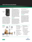
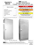
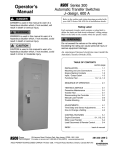
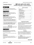
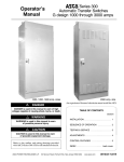
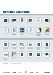
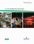
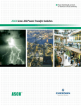
24-hour protection, no matter when trouble strikes ASCO S eries 300 Power Transfer Switches for Power Outage Protection Where would you be without a constant flow of electrical power? We often take for granted that power will always be around when we need it. In reality, power failures are common, and when the power goes out, your business suffers. Power failures are unpredictable. They can occur at any time and for any number of reasons — a bolt of lightning, a power surge, a blackout, an accident or even equipment failure. They come without warning and often at the most inconvenient times. It’s for this reason that many businesses and other entities have invested in emergency power backup systems. Typically, the system consists of an engine generator and an automatic 2 transfer switch (ATS) that transfers the load from the utility to the generator. An ATS with built-in control logic monitors your normal power supply and senses interruptions and unacceptable abnormalities. When the utility power fails, the ATS automatically starts the engine generator and transfers the load after the generator has reached proper voltage and frequency. This happens in a matter of seconds after the power failure occurs. When the utility power has been restored, the ATS will automatically switch the load back and, after a time delay, shut down the engine generator. With an ATS, you are protected 24 hours a day, seven days a week. Typical Applications Telecom Agriculture In the telecommunications industry, providing a high level of service and dependability is crucial. Lost power means an interruption in service for your customers and lost business for your company. For instance, with cell sites scattered across a wide geographical region and in many remote areas, the chances of an interruption in power are increased, making an ATS a valuable resource at each location. To maintain dependable service, each cell site must be monitored 24 hours a day. This can be very difficult without some type of remote monitoring and testing capability. The Series 300 Transfer Switch, combined with ASCO’s monitoring and control management system, is a cost-effective, packaged solution that can achieve both of these challenging objectives without a major investment at each cell site. With ASCO’s connectivity solutions, you can remotely monitor and control numerous sites from around the corner or across the world. Maintaining electrical power is vital to an agriculture operation. If the flow of power is interrupted, your operation will be at risk unless the backup generator is quickly activated. A prolonged power outage can affect numerous aspects of the operation, from housing and feeding livestock to processing and producing the end product. With an ASCO Series 300 Transfer Switch, power will automatically be transferred over to your backup generator, eliminating the need to manually switch from utility to generator. When power is restored, the ASCO Series 300 Transfer Switch will, after an adjustable time delay to allow for utility stabilization, automatically switch the load back to the utility service. Commercial / Retail, Light Industrial The retail industry is very competitive. An electrical power failure can have a dramatic impact on a retailer’s bottom line. If power is interrupted during peak shopping times, the effect can be extremely damaging to present and future business. A power interruption will not only suspend shopping, it can also create safety problems, result in lost transaction data, lost account information and possible damage to data collection equipment. In addition, retailers who rely on controlled climates to protect valuable inventory could suffer even greater losses, especially if the power failure occurs at a time when no one is available to rectify the situation. To avoid any of these power outage problems, simply install a backup generator with an ASCO Series 300 Transfer Switch, and your power outage concerns will be a thing of the past. Municipal The ASCO Series 300 Transfer Switch can be a critical component of a municipal government’s emergency power backup system. Residents of townships, cities and counties rely on police, fire, ambulance/first aid and other critical public sector services. An interruption in power can affect the ability of emergency services to effectively respond to the needs of the community. When time is a critical factor, such as when responding to a fire alarm or an emergency call, an ASCO Series 300 Transfer Switch can be a lifesaver, by automatically switching to power from the backup generator. While not all municipal services are a matter of life and death, they are always expected to be there. 3 Series 300 Power Transfer Switches Maximum Reliability & Excellent Value With a Series 300 Transfer Switch, you get a product backed by ASCO Power Technologies, the industry leader responsible for virtually every major technological advance in the Transfer Switch industry. The ASCO Series 300 was designed for one purpose–to automatically transfer critical loads in the event of a power outage. Each and every standard component was designed by ASCO engineers for this purpose. The Series 300 incorporates the Group G controller with enhanced capabilities for dependable operation in any environment. A user-friendly control interface with a 128x64 graphical LCD display and intuitive symbols allow for ease of operation while visual LED indicators display the transfer switch status. Operating parameters and feature settings can be adjusted without opening the enclosure door. The rugged construction and proven performance of the ASCO Series 300 assure the user of many years of complete reliability. The Series 300 is even designed to handle the extraordinary demands placed on the switch when switching stalled motors and high inrush loads. ASCO’s Series 300 modular, compact design makes it easy to install, inspect and maintain. All parts are accessible from the front so switch contacts can be easily inspected. Features • The Series 300 is listed to UL 1008 standard for total system loads and CSA standard C22.2 for automatic transfer switches. • Meets NFPA 110 for Emergency and Standby Power Systems and the National Electrical Code (NEC) Articles 700, 701 and 702. UL1008 Withstand and Close-on Ratings for ASCO Series 300 Group G Products 1,2 (RMS Symmetrical Amperes) Frame Switch Ratings (Amperes) Transfer Switches Current Limiting Fuses 480V Max. 600V Max. Specific Breaker Max. Class 240V Max. Size, A 480V Max. 600V Max. D 30 100kA- 60J 22kA22kA10kA 35kA 35kA 200RK1 D 70 - 100 42kA 22kA 10kA 200kA35kA 200 J 35kA 35kA 200RK1 D 150 65kA 25kA 10kA 200kA 35kA 200 J D 200 200kA - 200 J 65kA25kA10kA D 230 100kA - 300 J 65kA25kA10kA E 260, 400 200kA - 600 J 65kA42kA35kA 1504, 2004 J 2304, 260 200kA 200kA 600 J 65kA50kA42kA 400 J 600 200kA 200kA 800 L 65kA50kA42kA H 600 200kA 200kA 800 L 65kA65kA65kA H 800 - 1200 200kA 200kA 1600 L 65kA 65kA 65kA G 1000 - 1200 200kA 200kA 2000 L 85kA 85kA 85kA G 1600 - 20003 200kA 200kA 2500 L 85kA3 85kA3 85kA3 G 2600 - 3000 200kA 200kA 4000 L 100kA 100kA 100kA G 3200 200kA - 4000 L 100kA100kA G 4000 200kA 200kA 5000 L 100kA100kA100kA Notes: 4 1. All WCR values indicated are tested in accordance with the requirements of UL 1008, 7th Edition. See ASCO Pub. 1128 for more WCR information. 2. Application requirements may permit higher WCR for certain switch sizes. 3. Front connected only. 4. J150, 200, 230 Amperes available in 3ADTS and 3NDTS only. Fig. 1: ASCO Power Transfer Switch rated 200 amperes • Restriction of Hazardous Substances (RoHS) compliant controller. 30 • through 3000 amperes in a compact design. temperature range of • Switch operating 0 to +40o C. • Available to 600 VAC, single or three phase. • True double-throw operation: The single solenoid design is inherently inter-locked and prevents connections to both sources at the same time. No • danger of the Series 300 ATS transferring loads to a dead source because the unique ASCO single-solenoid operator derives power to operate from the source to which the load is being transferred. • Easy-to-navigate 128x64 graphical LCD display with keypad provides LED indicators for switch position, source availability, not in auto mode, and alert condition. • Integrated multilingual user interface for configuration and monitoring. • Delayed transition operation is now available (Dual Operator Configuration). • Non-automatic operation can be selected using the key pad without opening enclosure door. • Relay expansion module with extra relays for accessory outputs (optional). • Includes soft keys for test function and time delay bypass as standard features. • Emergency source failure alert indication. • Historical event log (optional). • Statistical ATS system monitoring information. • Diagnostic functions. • Password protection to prevent unauthorized tampering of settings. • Adjustable time-delay feature prevents switch from being activated due to momentary utility power outages and generator dips. Auxiliary contacts to indicate position of main • contacts. Two (2) for normal and two (2) emergency position • Supplied with solid neutral termination. • Optional switched neutral pole available. • Field modification accessory kits available. • Available for immediate delivery. Series 300 Power Transfer Switches Designed to Fit Anywhere The ASCO Series 300 product line represents the most compact design of automatic power transfer switches in the industry. With space in electrical closets being at a premium, the use of wall- or floor-mounted ASCO Power Transfer Switches assure designers optimum utilization of space. All transfer switches through 2000 amperes are designed to be completely front accessible. This permits the enclosures to be installed flush against the wall and still allow installation of all power cabling and connections from the front of the switch. Cable entrance plates are also standard on the 1600 and 2000 amperes units to install optional side-mounted pull boxes for additional cable bending space. Fig. 3: ASCO Power Transfer Switch rated 400 amperes Fig. 4: ASCO Power Transfer Switch rated 600 amperes Fig. 6: ASCO Power Transfer Switch rated 2000 amperes shown in Type 3R enclosure Fig. 2: ASCO Power Transfer Switch rated 200 amperes Fig. 5: ASCO Power Transfer Switch rated 1000 amperes Fig. 7: ASCO Power Transfer Switch rated 3000 amperes 5 Series 300 New Microprocessor Controller The Series 300 incorporates the group “G” controller with enhanced capabilities for dependable operation in any environment. Time Delays • Engine start time delay – delays engine starting signal to 2) SE and ER Relay Controller/TS Interface Plug Control Power Transformers Battery to Maintain Engine Exerciser Clock Settings Power Supply Jumper Card Dip Switches for Voltage/Frequency and Feature Functions 485 Configuration Dip Switches Mounting Location for Accessory Dongle Mounting Location for Current Sensing Card NR Relay override momentary normal source outages, adjustable from 0 to 6 seconds (Feature 1C). Emergency source stabilization time delay to ignore • momentary transients during initial generator set loading, adjustable from 0 to 4 seconds (Feature 1F). Re-transfer to normal time delay with two settings • (Feature 3A). • Power failure mode – 0 to 60 minutes • Test mode – 0 to 10 hours • Unloaded running time delay for engine cooldown, adjustable from 0 to 60 minutes (Feature 2E). Pre• and post-signal time delay for selective load disconnect with a programmable bypass on source failures, adjustable from 0 to 5 minutes (specify ASCO optional accessory 31Z). Optional fully programmable engine exerciser with seven • independent routines to exercise the engine generator, with or without loads, on a daily, weekly, bi-weekly or monthly basis (specify ASCO optional accessory feature bundle 11BE). Delayed transition load disconnect time delay, adjustable • from 0 to 5 minutes (3ADTS/3NDTS configuration only). CAN Bus Port Customer Control Interface RS 485 Port (Optional) Enabled with Feature Bundle 11BE Fig. 8: ASCO Series 300 Microprocessor Controller Features ControlPerformance and Display Panel • Easy-to-navigate 128x64 graphical LCD display with keypad 600 volt spacing per UL and CSA standards. Meets or exceeds the requirements for Electromagnetic Compatibility (EMC). IEEE C37.90 providesIECLED for switch position, source 61000 indicators – 4 - 2 Electrostatic Discharge Immunity IEC 61000 – 4 - in 3 Radiated RF Field Immunity and alert condition. It also availability, not auto mode, IEC 61000 – 4 - 4 Electrical Fast Transient/Burst Immunity includes IECtest and time delay bypass soft keys. 61000 – 4 - 5 Surge Immunity IEC 61000 – 4 - 6 Conducted RF Immunity CISPR 11 – Conducted RF Emissions and Radiated RF Emissions Voltage, Frequency & Current Sensing • 3-phase under and over voltage settings on normal and single phase sensing on emergency source. Under and over frequency settings on normal and emergency. • True RMS voltage sensing with +/-1% accuracy. • Frequency sensing accuracy is +/- 0.1Hz. • Voltage and frequency parameters adjustable in • 1% increments. • Selecting settings: single or three phase voltage sensing on normal, and single phase sensing on emergency; 50 or 60Hz. 3-phase voltage unbalance on normal. Load current sensing card (optional). • 6 Standard Selectable Features • Inphase monitor to transfer motor loads, without any intentional off time, to prevent inrush currents from exceeding normal starting levels. • Engine exerciser to automatically test backup generator each week, with or without load 20 minutes not adjustable. • Commit to transfer. • Selective load disconnect circuit to provide a pre-transfer and/or post-transfer signal when transferring from emergency to normal and/or normal to emergency. • Re-transfer to normal through soft keys on user interface permits selection of “manual” or “automatic” operation. • 60Hz or 50Hz selectable switch. Three-/single- phase selectable switch. Remote Control Features External inputs for connecting: • Remote test switch. • Remote contact for test or peak shaving applications. If emergency source fails, switch will automatically transfer back to normal source if acceptable. • Inhibit transfer to emergency. • Remote time delay bypass switch emergency to normal. Series 300 Group G Offers Sophisticated Functionality The new Group G controller offers an intuitive, easy-tonavigate 128*64 graphical LCD display with soft keypad and provides six (6) LED indicators. • Source Availability • Switch Position (green for normal, red for emergency LED) • Common Alarm components are required for efficient operation). (green for normal, red for emergency LED) application flexibility). Multiple source-sensing capabilities of voltage, frequency (under frequency sensing on normal and emergency sources), and optional current card, single and three phase (does not require an external metering device). The controller allows for open or delayed transition transfer operation (both automatic, and non-automatic configurations). • “Not In Auto” (amber LED) (amber LED) The ASCO group “G” controller is self-contained with an integrated display (no other An integrated multilingual user interface for configuration and monitoring (this design approach allows greater Fig. 9: Door-Mounted Control & Display Panel 1 2 1 Common Alarm 2 Not In Auto Indicator 3 Scroll, Up/Down Arrows 4 Escape Key 4 3 6 5 Enter Key 5 6 LED Source Availability and Switch Position Indicators Transfer / Time Delay Override control push-button Control Status Source Status Alarm Status Controller Information Main Menu/ Settings Settings/ Engine Exerciser Settings/General/ Communications Settings/General/ Common Alarms Main Menu/ Event Logging Main Menu/ Statistics Main Menu/ Factory/Diagnostics Main Menu/ About 7 Series 300 ATS Optional Accessories Accessory 1UP Accessory 73 UPS back up power to allow controller to run with LCD display for 30 seconds without AC power. Surge Suppressor (TVSS) Rated 65kA. Accessory 62W Accessory 11BE Feature Bundle: Audible alarm with silencing feature to signal each time switch transfers to emergency. A fully programmable engine exerciser with seven independent routines to exercise the engine generator with or without loads, on a daily, weekly, bi-weekly or monthly basis. Engine exerciser setting can be displayed and changed from the user interface keypad. Accessory 37B 6' Extension harness for units shipped open type to accommodate customer mounting of controls and switch. Accessory 37C Event Log display shows the event number, time and date of event, event type, and event reason (if applicable). A maximum of 300 events can be stored. 9' Extension harness for units shipped open type to accommodate customer mounting of controls and switch. RS 485 Communications Port Enabled Common Alarm Output Contact Power Meter on load side (includes shorting block and CTs) Accessory 18RX Relay expansion module (REX) provides for some commonly used accessory relays, includes one form C contact for source availability of normal (18G), and one form C contact for availability of emergency (18B) (contact rating 5 amperes @ 30Vdc or @125 VAC resistive). Additional output relay is provided, the default is to indicate a common alarm. (See operator’s manual for configurable options.) Accessory 23GA1 (Single Phase) and 23GB (Three Phase) Load current metering card measures either single or three phase load current. Note 1: This feature is not available with a Power Meter Option (135L). Accessory 44A Strip Heater with thermostat for extremely cold areas to prevent condensation and freezing of this condensation. External 120 volt power source required. Accessory 135L2 Note 2: This feature is not available with Load Current Metering Option (23GA or 23GB). Accessory 30A3 Shedding circuit initiated by opening of a customer-supplied contact. Accessory 30B*3 Load-shedding circuit initiated by removal of customer-supplied voltage. (*Specify Voltage) Accessory 30AA3 Load-shedding circuit initiated by opening of a customer-supplied contact. Accessory 30BA*3 Load-shedding circuit initiated by removal of customer-supplied voltage. (*Specify Voltage) Note 3: Accessory 30A and 30B* are only available for 3ATS only; accessory 30AA and 30BA* are only available for 3ADTS. Accessory 44G Strip Heater with thermostat, wired to load terminals: 208-240, 360-380, 460-480, 550-600 volts. Contains wiring harnesses for all transfer switch sizes. Accessory 72EE Connectivity Module enabling remote monitoring and control capabilities (pages 12-14) Field Conversion Kits for Series 300 Transfer Switches Kit No. 8 Fig. 10: Strip Heater Kit (Accessory 44G) Fig. 11: Relay Expansion Module (Accessory 18RX) Fig. 12: Load Current Card (Accessory 23GA/GB) Fig. 13: Programmable Engine Exerciser Description 935147 Feature Bundle Includes Engine Exerciser/Event Log/RS 485/ Common Alarm Output Contact (Acc. 11BE) Dongle 935148 REX Module with Source Availability Contacts (Acc. 18RX) 935149 UPS to allow controller to run for 30 seconds minimum without AC Power (Acc. 1UP) 935150 1/3 Phase load current sensing card only (Acc. 23GA/GB) K613127-001 Strip Heater (125 watt) 120 volt (Acc. 44A) K613127-002 Strip Heater (125 watt) 208-480 volt (Acc. 44G) 948551 Quad-Ethernet Module (Acc. 72EE) K609027 Cable Pull Box (1600-2000 amperes) Fig. 14: Accessory 1UP UPS Backup Power Series 300 Power Transfer Switches Series 300 Non-Automatic Transfer Switching (3NTS) ASCO non-automatic transfer switches are generally used in applications in which operating personnel are available and the load is not an emergency type requiring automatic transfer of power. They can also be arranged for remote control via ASCO’s connectivity products. 3NTS Features: •ASCO Non-Automatic Transfer Switches are electrically held, and manually initiated via soft keys on the user interface panel. •Sizes range from 30 through 3000 amperes. •Microprocessor based controller provides for addition of optional accessories. •Controller prevents inadvertent operation under low voltage condition. •Source acceptability lights inform operator if sources are available to accept load. •Source inphase monitor to transfer motor loads between live sources. •Two auxiliary contacts closed when transfer switch is connected to normal and two closed on emergency standard feature 14AA/14BA. Fig. 15: ASCO 3NTS 400 Amperes Type 1 Enclosure Series 300 Delayed Transition Transfer Switching (3ADTS/3NDTS) ASCO Delayed Transition Transfer Switches are designed to provide transfer of loads between power sources with a timed load disconnect position for an adjustable period of time. 3ADTS/3NDTS Features: •Sizes from 150 through 3000 amperes. •Reliable field proven dual solenoid operating mechanisms. •Mechanical interlocks to prevent direct connection of both sources. •Adjustable time delay for load disconnect (0 to 5 minutes). •Available in manual operation configuration (3NDTS). •Available with optional load shed feature for (3ADTS). Fig. 16: ASCO 3ADTS/3NDTS 400 Amperes Type 1 Enclosure 9 Series 300 Transfer Switch Ordering Information To order an ASCO Series 300 Power Transfer Switch, complete the following catalog number: + A TS + A + Neutral Code Product A N TS Conventional 2 Position Automatic + NonAutomatic DTS Delayed Transition A Solid Neutral B1 Switched Neutral 3 600 + Phase Poles Amperes 2 Poles 1o Continuous rating 3 Poles 3o 302, 702, 1042, 1505, 2004,5, 2302,4,5, 2602,5, 4002,5, 6005, 8005, 10005, 12005, 16005, 20005, 26005, 30005 Notes: 1. Specify neutral code “C” for 260 and 400 amperes only for 3ATS/3NTS. 2. Switch sizes 30-600 amperes supplied in non-secure enclosures as standard. 3. 115-120 volt available for 30-400 amperes only. For other voltages contact ASCO. 4. 200 and 230 amperes rated switches for use with copper cable only. 5. Switch sizes 800-3000 amperes, and 150-400 amperes 3ADTS/3NDTS provided in secure type outdoor enclosures when required. 6. Use 3R for 1200, 2000, 2600, and 3000. 7. Type 304 stainless steel is standard. Suitable for indoor or outdoor use where there may be caustic or alkali chemicals in use. N + Voltage Code A3 B3 C D E F H J K L M N Q R 115 120 208 220 230 240 380 400 415 440 460 480 575 600 + GX C + Controller Code G GX Optional Accessories Enclosure 0 Open Type C Type 1 (Standard) F Type 3R Non-Secure2 G Type 42 Non-Secure H Type 4X2 Non-Secure L Type 122 Non-Secure M Type 3R Secure Double Door N Type 4 Secure Double Door P Type 4X Secure Double Door 304 SS Q Type 12 Secure Double Door R Type 3RX7,8 Secure Double Door 304 SS (zero) To provide an improved reduction in corrosion of salt and some chemicals, optional type 316 stainless steel is recommended. This is the preferred choice for marine environments. 8. Available on switches rated 1200, 2000, 2600, and 3000 amperes. 9. When temperatures below 32oF can be experienced, special precautions should be taken, such as the inclusion of strip heaters, to prevent condensation and freezing of this condensation. This is particularly important when environmental (Type 3R, 4) are ordered for installation outdoors. 10. Type 3R enclosures are not suitable for installations subject to wind blown rain or snow. Use type 4 enclosures where available or install supplemental shelter protection around the 3R enclosure. Series 300 External Power Connections Size UL-Listed Solderless Screw-Type Terminals Switch Rating (Amperes) 30-230 2 260, 400 600 800, 1000, 1200 1600, 2000 2600, 3000 Ranges of AL-CU Wire Sizes (Unless Specified Copper Only) One #14 to 4/0 AWG Two 1/0 AWG to 250 MCM or One #4 AWG to 600 MCM Two 2/0 AWG to 600 MCM Four 1/0 to 600 MCM Six 1/0 to 600 MCM Twelve 3/0 to 600 MCM Notes: 1. All Series 300 switches are furnished with a solid neutral plate (unless switched neutral configuration is specified) and terminal lugs. 2. 200 and 230 amperes rated switches for use with copper cable only. Refer to paragraph 310.15 of the NEC for additional information. 3. Use wire rated 75oC minimum for all power connections. Extended Warranties for Series 300 Transfer Switches (3ATS/3NTS/3ADTS/3NDTS) Description 1 Year Extension (Total of 3 Years) 2 Year Extension (Total of 4 Years) 3 Year Extension (Total of 5 Years) 10 Notes: 1. Standard warranty is (24) months, 2 years from date of shipment, extended warranty is in addition to the two years, for a total of, 3, 4, or 5 years. 2. Refer to Publication 3223 for warranty terms and conditions. Series 300 Transfer Switch Dimensions and Shipping Weights UL Type 1 Enclosure1,2,3,4,5 Switch Rating Amperes 304,704,1004*,1044 1504, 2004 *Series 3NTS only 2303, 260, 400 150,200,230, 260,400 Series 3ADTS/3NTS only 600 800, 1000 1200 1600, 20001 2600, 30002 Phase Poles Neutral Code Width 2 2 3 3 2 2 3 3 2 2 3 3 2 2 3 3 2 2 3 3 2 2 3 3 3 3 3 3 A B A B A B3 or C A B3 or C A B A B A B A B A B A B A B A B A B A B 18(457) 18(457) 18(457) 18(457) 18 (457) 18 (457) 18 (457) 18 (457) 24(610) 24(610) 24(610) 24(610) 24 (610) 24 (610) 24 (610) 24 (610) 34 (864) 34 (864) 34 (864) 34 (864) 38 (965) 38 (965) 38 (965) 38 (965) 38 (965) 38 (965) 38 (965) 38 (965) Dimensions, In. (mm) Height Depth 31 (787) 31 (787) 31 (787) 31 (787) 48 (1219) 48 (1219) 48 (1219) 48 (1219) 56(1422) 56(1422) 56(1422) 56(1422) 63 (1600) 63 (1600) 63 (1600) 63 (1600) 72 (1829) 72 (1829) 72 (1829) 72 (1829) 87 (2210) 87 (2210) 87 (2210) 87 (2210) 87 (2210) 87 (2210) 91 (2311) 91 (2311) 13 (330) 13 (330) 13 (330) 13 (330) 13 (330) 13 (330) 13 (330) 13 (330) 14(356) 14(356) 14(356) 14(356) 17 (432) 17 (432) 17 (432) 17 (432) 20 (508) 20 (508) 20 (508) 20 (508) 23 (584) 23 (584) 23 (584) 23 (584) 23 (584) 23 (584) 60 (1524) 60 (1524) Approx. Shipping Notes: 1. Unit is designed for top cable Weight Lb. (kg) entry of emergency and load, and 69 (32) 72 (33) 72 (33) 75 (34) 117 (53) 125 (57) 125 (57) 133 (61) 196 (89) 202 (92) 202 (92) 208 (94) 316 (143) 324 (147) 324 (147) 332 (150) 431 (196) 460 (209) 460 (209) 489 (222) 581 (264) 611 (277) 611 (277) 639 (290) 1160 (525) 1160 (525) 1430 (649) 1495 (679) bottom entry of normal. A cable pull box is also available for all top or bottom cable access when required (optional accessory kit #K609027). Not required for type 3R, 4X and 12 enclosures where available. 2. Enclosures for 2600, 3000 amperes are free-standing with removable top, sides and back. 3. Neutral Code “B” for 230 amperes only. 4. Dimensions for 30-200 amperes when furnished with accessory 135L power meter, 18"W - 41"H - 13"D 5. Dimensional data is approximate and subject to change. Certified dimensions available upon request. UL Type 3R, 4 or 12 Enclosure1,2,3,4,5 Switch Rating Amperes Phase Poles Neutral Code 303,703,1003*,1043 1503, 2003 2 2 3 3 2 2 3 3 2 2 3 3 2 2 3 3 2 2 3 3 2 2 3 3 3 3 3 3 A B A B A 3 B or C A B3 or C A B A B A B A B A B A B A B A B A B A B *Series 3NTS only (Non-Secure Enclosure) 2302, 260, 400 (Non-Secure Enclosure) 150, 200, 230 260, 400 *Series 3ADTS/3NDTS only (Non-Secure Enclosure) 600 (Non-Secure Enclosure) 800, 1000 (Non-Secure Enclosure) 12006 (Secure Enclosure) 1600, 20002 (Secure Enclosure) 2600, 3000 (Secure Enclosure) Dimensions, In. (mm) Width Height Depth 17 1/2 (445) 17 1/2 (445) 17 1/2 (445) 17 1/2 (445) 18 (458) 18 (458) 18 (458) 18 (458) 24 (607) 24 (607) 24 (607) 24 (607) 24 (607) 24 (607) 24 (607) 24 (607) 34 (859) 34 (859) 34 (859) 34 (859) 41 (1037) 41 (1037) 41 (1037) 41 (1037) 42 1/2 (1074) 42 1/2 (1074) 41 (1037) 41 (1037) 35 (886) 35 (886) 35 (886) 35 (886) 50 1/2 (1284) 50 1/2 (1284) 50 1/2 (1284) 50 1/2 (1284) 63 (1593) 63 (1593) 63 (1593) 63 (1593) 63 (1593) 63 (1593) 63 (1593) 63 (1593) 72 (1821) 72 (1821) 72 (1821) 72 (1821) 95 1/2 (2415) 95 1/2 (2415) 95 1/2 (2415) 95 1/2 (2415) 95 1/2 (2529) 95 1/2 (2529) 95 1/2 (2529) 95 1/2 (2529) 11 5/8 (295) 11 5/8 (295) 11 5/8 (295) 11 5/8 (295) 14 1/3 (364) 14 1/3 (364) 14 1/3 (364) 14 1/3 (364) 18 1/5 (468) 18 1/5 (468) 18 1/5 (468) 18 1/5 (468) 18 1/5 (468) 18 1/5 (468) 18 1/5 (468) 18 1/5 (468) 20 (506) 20 (506) 20 (506) 20 (506) 33 1/2 (848) 33 1/2 (848) 33 1/2 (848) 33 1/2 (848) 47 (1189) 47 (1189) 74 (1872) 74 (1872) Approx. Shipping Notes: 1. When climate conditions at Weight Lb. (kg) installation site present 84 (38) 87 (40) 87 (40) 90 (41) 132 (60) 140 (63) 140 (63) 148 (67) 234 (106) 241 (109) 241 (109) 246 (112) 320 (145) 328 (148) 328 (148) 336 (152) 519 (236) 543 (246) 543 (246) 565 (257) 1131 (513) 1160 (526) 1160 (526) 1189 (539) 1705 (775) 1830 (832) 2150 (976) 2230 (1012) condensation risk, special precautions should be taken, such as the inclusion of space heaters, to prevent interior condensation and freezing of this condensation. 2. Neutral code “B” for 230 amperes only. 3. Dimensions for 30-200 amperes when furnished with a power meter 18"W - 48"H - 13"D 4. 30-1000 amperes switches are available in secure type enclosures, contact ASCO for details. 5. Dimensional data is approximate and subject to change. Certified dimensions available upon request. 11 Series 300 72EE Monitoring and Control Tablet Mobile Device Desktop 72EE enables basic local or remote monitoring for ASCO Series 300 Transfer Switches. WiFi Facility 300 ATS with 72EE ASCO 5700 CPMS Engine Generator Sample drawing for demonstration purposes only. Consult ASCO for exact connection specifications. 72EE Features Control Features Monitoring Features Connectivity Features •ATS Transfer/Re-transfer •ATS Timer Bypass •Generator Start •Generator Test •ATS and Generator Stats •Alarms •Voltage and Frequency •Statistics and Activity •Email Notifications •Event Log (300 Events) •Optional Monitoring Features •Modbus (over Ethernet or Serial) •SNMP Protocol •AES 128 Bit Encryption •Four Port Ethernet Switch — Energy Consumption, Acc 135L Required — Power Demand, Acc 135L Required 72EE Also Enables Enhanced PowerQuest CPMS Functionality •5310 Series Single Channel Annunciator •5350 Series Eight Channel Annunciator •5700 Critical Power Management Systems 12 Utility Series 300 72EE Monitoring Screens Fig. 18: Power Metering Screen Fig. 19: Events Screen Fig. 17: 72EE Home Page Dashboard Fig. 20: Configuration Fig. 21: About Content-rich monitoring screens enable real-time information for power metering, event logs, voltages, time delays and alerts. The 72EE also allows for remote switch transfer. 13 Series 300 72EE Connectivity Module Control Fig. 22: Accessory 72EE The ASCO 72EE Connectivity Module offers remote monitoring for Series 300 ATSs and 5210 Power Meter. For the ATS, the optional accessory 72EE provides remote ATS and generator control, monitoring and connectivity features via integrated web page dashboards. Once connected to an Ethernet, WiFi or cellular connection, the dashboards can easily be pulled up by any mobile or desktop device on the network by multiple users. The control capabilities allows remote transfer and retransfer of the ATS while allowing you to view time delays and bypass functions. The generators can also be called to start and stop for emergency situations as well as for testing and maintenance. Running the generator periodically ensures that the battery is charged for power anomalies and increases reliability. Generator pick-up and drop-out set points are also viewable for comprehensive understanding of control events. Monitoring Monitor transfer switch and generator health, system state, metering and review calculated transfer statistics and activity. Active control timer information allows the operator to anticipate an automated control action such as generator start or ATS transfer. The device can also interface with an email server to keep users up-to-date on alarms and critical power events with alerts. In addition the 72EE can interface to an optional 5210 Power Meter, (stand-alone or with the ATS Acc. 135L) for enhanced monitoring features such as power metering, demand and energy usage. Connectivity Connect and extract ATS and metering data using industry-standard open protocols such as Modbus and SNMP. An integrated four-port Ethernet switch maximizes connectivity options and flexibility. Embedded password protection will only allow access to appropriate users while utilizing AES 128-bit encryption for enhanced data security per National Institute of Standards and Technology (NIST). Additional Optional PowerQuest Components 5160 Connectivity Module ASCO 5160 Remote Connectivity Unit (RCU) provides 10 Ethernet and Dual-Fiber Optic connections in a NEMA 3R enclosure. 5210, 5220 Power Manager ASCO 5210 (Left) and 5220 (Right) Power Meters measure, displays and provides single- or 3-phase Energy and Power information ASCO 5221 Power Manager Unit ASCO 5221 Power Manager Unit (PMU) enables power measurement, discrete inputs for status and output relays for control of generators, breakers and other power equipment via 5700 Series CPMS solutions. 5310, 5350 Annunciators ASCO 5310 (Left) and 5350 (Right) ATS Remote Annunciators provide distributed monitoring of transfer switch position and source availability as well as transfer test and re-transfer control. 5710, 5750, 5790 Display Terminals 14 5700 Critical Power Management Systems (5790 Shown) provide various levels of monitoring, control and management capability of power equipment. It seamlessly monitors ASCO transfer switches as well as generators, breakers, paralleling busses, panel boards and other power equipment via a 5221 PMU. It consists of servers and touch-screen interfaces. FULFILL YOUR NEED Drill down for a closer look - Each transfer switch, generator, breaker and any other power equipment has its own dedicated screens. ASCO PowerQuest® Power Monitoring and Control Systems The PowerQuest® family is the most comprehensive communication, monitoring and control solution ever offered by Emerson Network Power. It empowers you. It provides the ability to test, manage loads, optimize the bus bar, remotely monitor and be aware of the status of your facility's utility source and on-site power. It provides reports for events, tests, energy use or settings, and gets data directly from generators and transfer switches. Whether users require standard monitoring and control or a comprehensive Critical Power Management System, PowerQuest can satisfy your needs. Hardware. Software. Installation and testing. Service. And upgrades and technology refreshes. A truly complete solution for all your communication, monitoring and control needs. This web-enabled management system is based on open protocols. As communications among equipment improve, so does the performance of critical power systems. Critical Power Management System (CPMS) HVAC Security UPS Static Transfer Switches Transfer Switches CPMS Display Terminal Fire Alarm Monitoring Building Management System (BMS) Internet Paralleling Control Switchgear Generators Remote Display Terminal PowerQuest provides monitoring, alarming and control of Critical Power Management Systems, which comprise transfer switches, paralleling control switchgear, gensets, circuit breakers, UPSs, loadbanks, distribution and other gear. It also integrates with building management systems. BE EMPOWERED PowerQuest can enable you to: • Monitor and control power transfer switches, paralleling control switchgear, gensets, breakers, UPS, bus bars and other equipment. • Monitor normal and emergency voltages and frequency and their settings. • Know transfer switch position and source availability. • Transfer and re-transfer loads for system testing. • View and adjust transfer switch time-delay settings. • Receive automatic alerts or selected system alarms on system operation via email or pager. • View transfer switch event log and know the transfer switch test schedule. • Generate reports for alarms, energy consumption, settings, historical logs and code-mandated tests. For more PowerQuest product information see publication 3245 15 Emerson Network Power - Global Headquarters 1050 Dearborn Drive Columbus, OH 43085 Tel: +1 614 888 0246 ASCO Power Technologies - Global Headquarters 50 Hanover Road Florham Park, NJ 07932 800-800-ASCO www.EmersonNetworkPower.com/ASCO www.ascoapu.com Emerson. Consider it Solved., Emerson Network Power and the Emerson Network Power logo are trademarks and service marks of Emerson Electric Co. ©2014 Emerson Electric Co. All rights reserved. Publication 1195 R16 © November, 2014 Printed in the U.S.A.