1
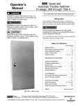
Power Switching & Controls for Business-Critical Continuity 24-hour protection no matter when trouble strikes ASCO S eries 300 Power Transfer Switches for Power Outage Protection Where would you be without a constant flow of electrical power? We often take for granted that power will always be around when we need it. In reality, power failures are very common. And when the power goes out, your business suffers. Power failures are unpredictable. They can occur at any time and for any number of reasons—a bolt of lightning, a power surge, a blackout, an accident or even equipment failure. They come without warning and often at the most inconvenient times. It’s for this reason that many businesses and other entities have invested in emergency power backup systems. Typically, the system consists of an engine 2 generator and an automatic transfer switch (ATS) which transfers the load from the utility to the generator. An ATS with built-in control logic monitors your normal power supply and senses any interruptions. When the utility power fails, the ATS automatically starts the engine and transfers the load after the generator has reached proper voltage and frequency. This happens in a matter of seconds after the power failure occurs. When the utility power has been restored, the ATS will automatically switch the load back, and after a time delay, it will shut down the engine. With an Automatic Transfer Switch, you are protected 24 hours a day, seven days a week. Typical Applications Telecom Agriculture In the telecommunications industry, providing a high level of service and dependability is crucial. Lost power means an interruption in service for your customers and lost business for your company. For instance, with cell sites scattered across a wide geographical region and in many remote areas, the chances of an interruption in power are increased, making Automatic Transfer Switches a valuable resource at each location. To maintain dependable service, each cell site must be monitored 24 hours a day. This can be very difficult without some type of remote monitoring and testing capability. The Series 300 Transfer Switch, combined with ASCO’s monitoring and control management system, is a costeffective, packaged solution which can help meet both of these challenging objectives without a major investment at each cell site. With ASCO’s connectivity solutions you can remotely monitor and control numerous sites from around the corner or around the world. Maintaining electrical power is vital to an agriculture operation. If the flow of power is interrupted, your operation could be at risk unless the backup generator is quickly activated. A prolonged power outage can affect numerous aspects of the operation, from housing and feeding livestock to processing and producing the end product. With an ASCO Series 300 Transfer Switch, power will automatically be transferred over to your backup generator, eliminating the need to manually switch from utility to generator. When power is restored, the ASCO Series 300 Transfer Switch will, after an adjustable time delay to allow for utility stabilization, automatically switch the load back to the utility service. Commercial / Retail, Light Industrial The retail industry is very competitive. An electrical power failure can have a dramatic impact on a retailer’s bottom line. If power is interrupted during peak shopping times, the effect could be extremely damaging to present and future business. A power interruption will not only suspend shopping, it can also create safety problems, result in lost transaction data, lost account information and damage to data collection equipment. In addition, retailers who rely on controlled climates to protect valuable inventory could suffer even greater losses, especially if the power failure occurs at a time when no one is available to rectify the situation. To avoid any of these power outage problems, simply install a backup generator with an ASCO Series 300 Transfer Switch and power outage concerns will be a thing of the past. Municipal The ASCO Series 300 Transfer Switch can be a critical component of a municipal government’s emergency power backup system. Residents of townships, cities and counties rely on police, fire, ambulance/ first aid and other critical public sector services. An interruption in power would affect the ability of emergency services to effectively respond to the needs of the community. When time is a critical factor, such as when responding to a fire alarm or an emergency call, an ASCO Series 300 Transfer Switch can be a lifesaver, switching power to the backup generator. While not all municipal services are a matter of life and death, they are always expected to be there. 3 Series 300 Power Transfer Switches Maximum Reliability & Excellent Value With a Series 300 Transfer Switch, you get a product backed by ASCO Power Technologies, the industry leader responsible for virtually every major technological advance in the Transfer Switch industry. The ASCO Series 300 was designed for one purpose–to automatically transfer critical loads in the event of a power outage. Each and every standard component was designed by ASCO engineers for this purpose. The rugged construction and proven performance of the ASCO Series 300 assure the user of many years of complete reliability. The Series 300 is even designed to handle the extraordinary demands placed on the switch when starting or restarting stalled motors and switching high inrush loads. ASCO’s Series 300 modular, compact design makes it easy to install, inspect and maintain. All parts are accessible from the front so switch contacts can be easily inspected. Features The Series 300 is listed to UL 1008 standard for Transfer Switch Equipment and CSA standard C22.2 for automatic transfer switches. Meets NFPA 110 for Emergency and Standby Power Systems and the National Electrical Code (NEC) Articles 700, 701 and 702. 30 through 3000 amps in a compact design. Available to 600 VAC, single or three phase. True double-throw operation: The single solenoid design is inherently inter-locked and prevents contacts from stopping between sources or from being in contact with both sources at the same time. UL Listed Withstand & Close-On Ratings Available Symmetrical Amperes RMS Switch Ratings Amps 30 70 - 200 230 260, 400 600 600 600 800,1000,1200 1600, 2000 2600, 3000 Notes: 4 When Used With Current Limiting Fuses Maximum Voltage When Used With Specific Circuit Breakers 100,000 200,000 100,000 200,000 200,000 200,000 200,000 200,000 200,000 200,000 480v/60Hz 480v/60Hz 480v/60Hz 480v/60Hz 600v/60Hz 480v/60Hz 240v/60Hz 600v/60Hz 600v/60Hz 600v/60Hz 10,000 22,000 22,000 42,000 42,000 50,000 65,000 65,000 85,000 100,000 1.Current – limiting fuse should be Class J type through 400 amps: use Class L type above 400 - amp fuse rating 2. Refer to publication 1128 for specific manufacturer’s breakers Fig. 1: ASCO Power Transfer Switch rated 200 amperes shown in Type 3R enclosure There’s no danger of the Series 300 ATS transferring loads to a dead source because the unique ASCO single-solenoid operator derives power to operate from the source to which the load is being transferred. Easy-to-read flush-mounted control and display panel provides LED indicators for switch position and source availability. It also includes test and time-delay bypass switches as standard features. Standard engine exerciser for weekly automatic testing of engine generator set with or without load. Adjustable time-delay feature prevents switch from being activated due to momentary utility power outages and generator dips. Supplied with solid neutral termination. Optional switched neutral pole available. Accessory kits available. Available for immediate delivery. Now available for service entrance applications. Contact Asco for assistance. Series 300 Power Transfer Switches Designed to Fit Anywhere The ASCO Series 300 product line represents the most compact design of automatic power transfer switches in the industry. With space in electrical closets being at a premium, the use of wall or floor-mounted ASCO Power Transfer Switches assures designers optimum utilization of space. All transfer switches through 2000 amps are designed to be completely front accessible. This permits the enclosures to be installed flush to the wall and still allows installation of all power cabling and connections from the front of the switch. Cable entrance plates are also standard on the 1600 and 2000 amp units to install optional side-mounted pull boxes for additional cable bending space. Fig. 3: ASCO Power Transfer Switch rated 400 amperes Fig. 4: ASCO Power Transfer Switch rated 600 Amperes Fig. 6: ASCO Power Transfer Switch rated 2000 amperes shown in Type 3R enclosure Fig. 2: ASCO Power Transfer Switch rated 200 amperes Fig. 5: ASCO Power Transfer Switch rated 1000 amperes Fig. 7: ASCO Power Transfer Switch rated 3000 amperes 5 Series 300 Microprocessor Controller The ASCO Microprocessor Controller is used with all sizes of Power Transfer Switches. It represents the most reliable microprocessor controller in the industry and includes, as standard, all of the voltage, frequency, control, timing and connectivity functions required for most emergency and standby power applications. Voltage & Frequency Sensing Adjustable three-phase, close-differential voltage sensing on normal source. Normal source pickup voltage is adjustable to 95% of nominal; drop-out is adjustable from 70% to 90% of nominal. Frequency sensing on emergency source. Pickup at 95% and dropout at 85% of nominal. Time Delays Fig. 8: ASCO Series 300 Microprocessor Controller Adjustable time delay to override momentary normal source outages to delay all transfer switch and enginestarting signals. Transfer to emergency time delay––Adjustable from 0 to 5 minutes for controlled timing of load transfer to emergency. Re-transfer to normal time delay––Adjustable to 30 minutes. Five-minute unloaded running time delay for emergency engine generator cool down. Four-second time delay to ignore momentary voltage and frequency transients during initial genset loading. Standard Selectable Features Fig. 9: Door-Mounted Control & Display Panel Inphase monitor to transfer motor loads, without any intentional off time, to prevent inrush currents from exceeding normal starting levels. Engine exerciser to automatically test backup generator each week—Includes control switch for testing with or without load. Selective load disconnect, double-throw contact to operate at an adjustable 0 to 20 second adjustable time delay prior to transfer and reset 0 to 20 seconds after transfer. 60 Hz or 50 Hz selectable switch. Three-phase/single-phase selectable switch. Remote Control Features Control and Display Panel Easy-to-read flush-mounted control and display panel provides LED indicators for switch position and source availability. It also includes test and time-delay bypass switches. 6 Terminal provisions for connecting: Remote test switch. Remote contact for test or for peak shaving applications. Circuit will be automatically bypassed if emergency source fails. Remote time-delay bypass switch. Series 300 Microprocessor Controller Battery to Maintain Engine Exerciser Clock Settings Re-transfer to Normal Adjustable Time Delay Simple and Accurate Adjustment of Voltage, Frequency and Time-Delay Settings Without Need for Meters and Variable Power Supplies Transfer to Emergency Adjustable Time Delay Dip Switches for Enabling Built-In Control Functions Serial Communication Port Customer Control Interfaces Fig. 10: Microprocessor Controller Performance Features 600 volt spacing per UL and CSA standards. Interfacing relays are industrial grade, plug-in type with dust covers. Meets or exceeds the requirements for Electromagnetic Compatibility (EMC). ANSI C37.90A/IEEE472 Voltage Surge Test NEMA ICS-109.21 Impulse Withstand Test Digital circuitry isolated from line voltages IEC 801-2 Electrostatic discharge (ESD) immunity ENV50140 and IEC 803-1: Radiated electromagnetic field immunity IEC 801-4 Electrical fast transient (EFT) immunity ENV50142 Surge transient immunity ENV50141: Conducted radio-frequency field immunity EN55011: Group 1, Class A conducted and radiated emissions Optically isolated RS-485 Serial Port EN61000- 4-11 voltage dips and interruptions immunity 7 Series 300 ATS Optional Accessories Accessory 11BG A programmable engine exerciser that provides for weekly or bi-weekly operation, includes one form C contact for source availability of normal and one contact for availability of emergency (contact rating 2 amps @ 30 Vdc, 0.5 amp @ 125 Vac resistive). The programmable engine exerciser incorporates a 7 day or 14 day time base with a digital readout display. Includes “with or without” load control selection for exerciser period. Accessory 14AA/14BA Auxiliary contacts to indicate position of main contacts. Two (2) for normal and two (2) for emergency position (one set is standard). Accessory 44A Strip Heater with thermostat for extremely cold areas to prevent condensation and freezing of this condensation. External 120 volt power source required. Fig. 11: Programmable Engine Exerciser with Source Availability Contacts (Accessory 11BG) Accessory 44G Strip Heater with thermostat, wired to load terminals: 208-240, 360-380, 460-480, 550-600 volts. Contains wiring harnesses for all transfer switch sizes. Accessory 72A/72E *See “Connectivity Products”, Page 18 Accessory 123 A protective window that includes a poly-carbonate frame and weather gasket to provide secure access to the membrane interface for the type 1 enclosures. This lockable cover is an alternative to providing 3R secure enclosures. Fig. 12: Strip Heater Kit (Accessory 44G) Field Conversion Kits for Series 300 Transfer Switches Kit No. Description K629830 Engine Exerciser and source availability contacts (Acc. 11BG) K613127-001 Strip Heater Kit (125 watt) 120 volt (Acc. 44A) K613127-002 Strip Heater Kit (125 watt) 208-480 volt (Acc. 44G) K609027 K473872-001 K755257-001 K754603-001 K778330-001 Cable Pull Box (1600-2000 amp) 6 FT Extension Harness1 Serial Module with or without power manager (Acc. 72A) Connectivity Module with or without power manager (Acc. 72E) Window Kit (Acc. 123) 1. For 30-200 Amp switches only, not available for 300SE, or 300L Fig. 13: Window Kit (Accessory 123) 8 Series 386 Non-Automatic Power Transfer Switches User-Initiated Control ASCO 386 non-automatic transfer switches are generally used in applications where operating personnel are available and the load is not an emergency type requiring automatic transfer of power. The power-switching mechanism and controller is the same hardware used on the highly reliable ASCO Series 300 transfer switches. ASCO 386s are furnished as standard with a momentary-type selector switch to initiate transfer and re-transfer. They can also be arranged for remote control via ASCO’s connectivity products. Electrical Features: Listed under UL 1008, CSA certified: - UL listed through 480 VAC. - CSA certified through 600 VAC. Door-mounted selector switch for local, manually initiated electrical control. Sizes from 30 through 3000 amps. Available to 600 VAC, 50 or 60 Hz. Rated for all classes of load transfer. 100% tungsten load ratings through 400 amps. Designed for emergency and standby applications. Same withstand and close-on rating as Series 300. Standard Selectable Control Features: I nphase monitor to transfer motor loads between live sources, without any intentional off time, to prevent inrush currents from exceeding normal starting levels. Selective load disconnect, double-throw contact to operate at an adjustable 0 to 20 second time delay prior to transfer and reset 0 to 20 seconds after transfer. High/Low nominal voltage setting. Allows user to adjust for source low reduced voltage conditions in remote areas. 60 Hz or 50 Hz selectable switch. Single/Three-phase selectable switch. Control Features: Fig. 14: ASCO 386 400 Amp Type 1 Enclosure w/Optional Accessories 9C, 9D Source Availability Lights Switch position indicating signal lights. One auxiliary contact closed when transfer switch is connected to normal and one closed on emergency, standard feature 14A/14B. Optional Accessories: 6Q Key-operated, momentary source selector switch furnished instead of the standard selector switch. 9C, 9D Source availability lights to provide operator with a local indication of power source availability. Accessory 14AA/14BA auxiliary contacts to indicate Fig. 15: Control and Display Panel position of main contacts. Two (2) for normal position and two (2) for emergency position (one set is standard). 72A Serial module (5110) is used to allow local or remote communications with ASCO POWERQUEST® connectivity products. Special Enclosures (Specify by appropriate code in catalog number): Type 3R: Rain-tight Type 4: Weatherproof Type 12: Oil Tight 72E Connectivity Module 5150 is used to bring several different serial devices that communicate at different baud rates and with different protocols to a common Ethernet media. 9 Series 300 & 386 Transfer Switch Ordering Information To order an ASCO Series 300 Power Transfer Switch, complete the following catalog number: 300 + B + Product Neutral Code Voltage Code Continuous rating 3 poles, 30, 70, 104, 150, 2004, 3Ø 2304, 260, 400, 600, 800, 1000, 1200, 1600, 2000 26005, 30005 1 Switched Neutral N + Amperes 2 poles, 1Ø Solid Neutral B 600 Poles Blank 300 3 + A3 B3 C D E F H J K L M N Q R 1 + X + C + Enclosure Options Controller + Blank Open Type Insert “X” 115 120 208 220 230 240 380 400 415 440 460 480 575 600 If optional accessories are required 1 C Type 1 (Standard) F Type 3R G Type 4 H Type 4X Type 12 M Type 3R Secure N Type 4 Secure P Type 4X Secure Double Door SS R Type 3RX Secure Double Door SS + 480 V 60 Hz Optional Accessories 11BG Programmable Engine Exerciser 14AA/14BA 2 L 11CD Auxiliary Contacts (2 sets) Specific Volt & Freq This information is necessary to allow correct control settings prior to shipment 44A, 44G 2 Strip Heater w/ Thermostat 72A Serial Module 72E 6 Connectivity Module 123 Window Kit 6,7 To order an ASCO Series 386 Transfer Switch, complete the following catalog number: 386 + Product 386 B + Neutral Code A 3 Phase Poles Solid Neutral 2 poles, 1Ø B1 3 poles, 3Ø Switched Neutral 600 + N + Voltage Code Amperes Continuous rating 30, 70, 100, 150, 2004, 2304, 260, 400, 600, 800, 1000, 1200, 1600, 2000, 2600, 30005 A3 B3 C D E F H J K L M N Q R 115 120 208 220 230 240 380 400 415 440 460 480 575 600 + 1 + Controller 1 X C + + Options Enclosure Insert “X” Blank Open Type Type 1 C (Standard) If optional accessories are required 9C/9D + 480 V 60 Hz Optional Accessories Specific Volt & Freq 6Q This information is necessary to allow correct control settings prior to shipment Key-Operated Control F Type 3R G Type 4 H Type 4X L Type 12 2 Source Availability Lights M Type 3R Secure Auxiliary Contacts N Type 4 Secure P Type 4X Secure Double Door SS R Type 3RX Secure Double Door SS 2 9C/9D 14AA/14BA 72A 6 Serial Module All Accessories 6,7 Notes: 1. Specify neutral code “C” for 260 and 400 amperes only. 2. Available 30-1000, and 1600 amps. Use Type 3R for 1200, 2000, 2600 and 3000 amp applications. 3. 115-120 volt available 30-400 amps only. For other voltages contact ASCO. 4. 200 and 230 amp rated switches for use with copper cable only. 5. Secure 3R type provided as standard for 2600-3000 amp when outdoor enclosure is required. 6. Type 304 Stainless Steel is standard. Suitable for indoor or outdoor use where there may be caustic or alkali chemicals in use. To provide an improved reduction in corrosion of salt and some chemicals, optional type 316 Stainless Steel is recommended. This is a preferred choice for marine environments. 7. Available on switches rated 1200, 2000, 2600, and 3000 Amps. Extended Warranties for Series 300 Transfer Switches 10 Catalog No. Description 2EXW300 Two-Year Extended Warranty (Parts & Labor) 3EXW300 Three-Year Extended Warranty (Parts & Labor) 4EXW300 Four-Year Extended Warranty (Parts & Labor) 5EXW300 Five-Year Extended Warranty (Parts & Labor) 72E Connectivity Module Series 300 & 386 Transfer Switch Dimensions and Shipping Weights UL Type 1 Enclosure4 Switch Rating Amps Phase Poles Neutral Code Width 2 2 3 3 2 2 3 3 2 2 3 3 2 2 3 3 2 2 3 3 3 3 3 3 A B A B A B3 or C A B3 or C A B A B A B A B A B A B A B A B 17 1/2 (445) 17 1/2 (445) 17 1/2 (445) 17 1/2 (445) 18 (457) 18 (457) 18 (457) 18 (457) 24 (610) 24 (610) 24 (610) 24 (610) 34 (864) 34 (864) 34 (864) 34 (864) 38 (965) 38 (965) 38 (965) 38 (965) 38 (965) 38 (965) 38 (965) 38 (965) 30, 70, 100*, 104 150, 200 *Series 386 only 2303, 260, 400 600 800, 1000 1200 1600, 20001 2600, 30002 Dimensions, In. (mm) Height Depth 31 (787) 31 (787) 31 (787) 31 (787) 48 (1219) 48 (1219) 48 (1219) 48 (1219) 63 (1600) 63 (1600) 63 (1600) 63 (1600) 72 (1829) 72 (1829) 72 (1829) 72 (1829) 87 (2210) 87 (2210) 87 (2210) 87 (2210) 87 (2210) 87 (2210) 91 (2311) 91 (2311) 11 5/8 (295) 11 5/8 (295) 11 5/8 (295) 11 5/8 (295) 13 (330) 13 (330) 13 (330) 13 (330) 17 (432) 17 (432) 17 (432) 17 (432) 20 (508) 20 (508) 20 (508) 20 (508) 24 (610) 24 (610) 24 (610) 24 (610) 24 (610) 24 (610) 60 (1524) 60 (1524) Approx. Shipping Notes: 1.Unit is designed for top cable Weight Lb. (kg) entry of emergency & load and 69 (32) 73 (33) 73 (33) 75 (34) 100 (45) 110 (50) 100 (45) 120 (55) 263 (119) 270 (122) 270 (122) 277 (126) 450 (204) 475 (217) 475 (217) 500 (228) 685 (312) 705 (321) 705 (321) 725 (328) 925 (419) 975 (441) 1700 (771) 2135 (969) bottom entry of normal. A cable pull box is also available for all top or bottom cable access when required (optional accessory kit #K609027). Not required for type 3R, 4X & 12 enclosures where available. 2.Enclosures for 2600, 3000 amps are free-standing with removable top, sides & back. 3. Neutral Code “B” for 230 amperes only. 4. Dimensional data is approximate and subject to change. Certified dimensions available upon request. UL Type 3R, 4 or 12 Enclosure1,4,5,6 Switch Rating Amps Phase Poles Neutral Code 2 2 3 3 2 2 3 3 2 2 3 3 2 2 3 3 2 2 3 3 3 3 3 3 A B A B A B3 or C A B3 or C A B A B A B A B A B A B A B A B 30, 70, 100*, 104 150, 200 *Series 386 only 2303, 260, 400 600 800, 1000 12006 1600, 20002 2600, 3000 Dimensions, In. (mm) Width Height Depth 17 1/2 (445) 17 1/2 (445) 17 1/2 (445) 17 1/2 (445) 18 (458) 18 (458) 18 (458) 18 (458) 24 (610) 24 (610) 24 (610) 24 (610) 34 (864) 34 (864) 34 (864) 34 (864) 41 (1043) 41 (1043) 41 (1043) 41 (1043) 41 (1043) 41 (1043) 41 (1043) 41 (1043) 35 (886) 35 (886) 35 (886) 35 (886) 50 1/2 (1284) 50 1/2 (1284) 50 1/2 (1284) 50 1/2 (1284) 63 (1602) 63 (1602) 63 (1602) 63 (1602) 75 (1907) 75 (1907) 75 (1907) 75 (1907) 94 1/2 (2403) 94 1/2 (2403) 94 1/2 (2403) 94 1/2 (2403) 95 1/2 (2428) 95 1/2 (2428) 95 1/3 (2424) 95 1/3 (2424) 11 5/8 (295) 11 5/8 (295) 11 5/8 (295) 11 5/8 (295) 14 1/3 (364) 14 1/3 (364) 14 1/3 (364) 14 1/3 (364) 18.50 (470) 18.50 (470) 18.50 (470) 18.50 (470) 20 (508) 20 (508) 20 (508) 20 (508) 33 1/2 (852) 33 1/2 (852) 33 1/2 (852) 33 1/2 (852) 62 (1577) 62 (1577) 74 (1882) 74 (1882) Approx. Shipping Notes: 1. 30-1000 amps non-secure enWeight Lb. (kg) closure. 1200-3000 amps secure 84 (38) 87 (40) 87 (40) 90 (41) 132 (60) 140 (63) 140 (63) 148 (67) 664 (300) 672 (303) 672 (303) 680 (307) 664 (300) 672 (303) 672 (303) 680 (307) 1131 (513) 1160 (526) 1160 (526) 1189 (539) 1810 (817) 1860 (843) 2005 (905) 2070 (938) enclosure 2. When climate conditions at installation site present condensation risk, special precautions should be taken, such as the inclusion of space heaters, to prevent interior condensation and freezing of this condensation. 3. Neutral code “B” for 230 amperes only. 4. Dimensions for switch sizes 30 1000 amperes suitable for Type 3R, 4, or 12 non secure enclosure, 1200 -3000 amperes only suitable for type 3R. 5. For 1200 ampere type 4, or 12 use 1600 amperes secure enclosure dimensions. 6. Dimensional data is approximate and subject to change. Certified dimensions available upon request. Series 300 & 386 External Power Connections Sizes UL-Listed Solderless Screw-Type Terminals Switch Rating (Amps) 30 - 230 Ranges of AL-CU Wire Sizes (Unless Specified Copper Only) 2 260, 400 600 800, 1000, 1200 1600, 2000 2600, 3000 One #14 to 4/0 AWG Two 1/0 AWG to 250 MCM or One #4 AWG to 600 MCM Two 2/0 AWG to 600 MCM Four 1/0 to 600 MCM Six 1/0 to 600 MCM Twelve 3/0 to 600 MCM Notes: 1. All Series 300 switches are furnished with a solid neutral plate (unless switched neutral configuration is specified) and terminal lugs. Specify “A” in catalog number to order a neutral plate on the series 386 switches. 2. 200 and 230 amp rated switches for use with copper cable only. Refer to paragraph 310.15 of the NEC for additional information. 3. Use wire rated 75oC minimum for all power connections. 11 Series 300SE Power Transfer Switch The ASCO Service Entrance Power Transfer Switch combines automatic power switching with the necessary disconnecting, grounding, and bonding required for use as service entrance equipment. The power transfer switch meets all National Electrical Code requirements for service entrance use. Transfer switches generally are installed at facilities that have a single utility feed and a single emergency power source. 600 - 3000 Amp Construction ASCO Series 300SE products use two types of construction. Products 400 amperes or less, utilize a single enclosure including a service (utility source) disconnect circuit breaker, as well as the power transfer switch, grounding and bonding provisions. Products 600 amperes and above, utilize a multi-section switchboard construction including a service equipment section containing the service (utility source) disconnect circuit breaker, grounding, and bonding provisions. A second section contains the power transfer switch. Fig. 16: ASCO Series 300 SE Rated 800 amperes Type 1 enclosure with Service Entrance Equipment Product Features: 70 - 400 Amp Construction Suitable for use as service entrance equipment. Listed to UL 891 (standard for switchboards) for 600 - 3000 amps, sizes and UL 1008 (standard for panel-boards) for 70 - 400 amps. Automatic Transfer Switch is listed to UL 1008 for total system loads Sizes available from 70 - 3000 amps, 600 VAC, 50 or 60 Hz, single or three phase Silver plated copper ground and neutral bus solderless screw type terminals Ground fault trip protection provided on sizes 1000 amps and above Available with solid or switched neutral Fig. 17: ASCO Series 300 SE rated 200 amperes in Type 1 enclosure with single source breakers Series 300SE Transfer Switch Ordering Information To order an ASCO Series 300SE Power Transfer Switch, complete the following catalog number: 3AUS + Product 3AUS B + 3 Neutral Code Phase Poles B1 2 poles, 1Ø Switched Neutral 3 poles, 3Ø + 400 Amperes Continuous Rating 70, 100, 150, 2006, 2256, 250, 400, 600, 800, 1000, 1200, 1600, 2000 2500, 3000 N + + Voltage Code A3 B3 C D E F H J K L M N Q R 115 120 208 220 230 240 380 400 415 440 460 480 575 600 1 + Controller 1 X C + Options Insert “X” If optional accessories are required + Enclosure Blank Open Type C Type 1 (Standard) F G H Type 3R Type 4X L Type 12 M Type 3R Secure N Type 4 Secure P Type 4X Secure Double Door SS R Type 3RX Secure Double Door SS Type 4 2 2 11CD + Specific Volt & Freq 11BG Programmable Engine Exerciser This information is necessary to allow correct control settings prior to shipment 14AA/14BA Auxiliary Contacts (2 sets) 44G Strip Heater w/Thermostat 72A Serial Module 6 72E Connectivity Module 73A Surge Suppressor 7,8 Notes: 12 1. Specify neutral code “C” for 250 and 400 amperes only. 2. Available 70-1000 ampacity. Use Type 3R for 1200-3000 amp applications. 3. 115-120 volt available 150-400 amps only. 4. A solid neutral is standard on 3AUS. 5. For switch sizes 70 - 225 amperes only. 240 V/60 Optional Accessories 6. 200, 225 amp rated switch suitable for use with copper cable only. 7. Type 316 Stainless Steel is standard. It provides an improved reduction in corrosion of salt and some chemicals. It is the preferred choice for marine environments. 8. Available only on switches rated 1200, 2000, 2600, and 3000 Amps. Series 300SE Transfer Switch Dimensions and Shipping Weights UL Type 1 Enclosure4 Switch Rating Amps Dimensions, In. (mm) Height Phase Poles Neutral Code Width 2 2 3 3 2 2 3 3 2 2 3 3 2 2 3 3 3 3 3 3 STD B STD B STD C STD C STD B STD B STD B STD B STD B STD B 36.5 (927) 36.5 (927) 36.5 (927) 36.5 (927) 36.5 (927) 36.5 (927) 36.5 (927) 36.5 (927) 38 (965) 38 (965) 38 (965) 38 (965) 38 (965) 38 (965) 38 (965) 38 (965) 38 (965) 38 (965) 38 (965) 38 (965) Phase Poles Neutral Code Width 2 2 3 3 2 2 3 3 2 2 3 3 2 2 3 3 3 3 3 3 STD B STD B STD C STD C STD B STD B STD B STD B STD B STD B 36(914) 36(914) 36(914) 36(914) 36(914) 36(914) 36(914) 36(914) 41(1041) 41(1041) 41(1041) 41(1041) 41(1041) 41(1041) 41(1041) 41(1041) 41(1041) 41(1041) 41(1041) 41(1041) 70, 100 ,150, 200, 225 250, 400 6001, 8001 10001, 12001 16001, 20001 25001, 30001 48.5 (1232) 48.5 (1232) 48.5 (1232) 48.5 (1232) 48.5 (1232) 48.5 (1232) 48.5 (1232) 48.5 (1232) 91 (2311) 91 (2311) 91 (2311) 91 (2311) 91 (2311) 91 (2311) 91 (2311) 91 (2311) 91 (2311) 91 (2311) 91 (2311) 91 (2311) Depth Approx. Shipping Weight Lb. (kg) 13.25 (337) 13.25 (337) 13.25 (337) 13.25 (337) 13.25 (337) 13.25 (337) 13.25 (337) 13.25 (337) 28 (711) 28 (711) 28 (711) 28 (711) 48 (1218) 48 (1218) 48 (1218) 48 (1218) 48 (1218) 48 (1218) 72 (1829) 72 (1829) 400 (185) 408 (188) 408 (188) 416 (192) 400 (185) 408 (188) 408 (188) 416 (192) 800 (370) 820 (378) 820 (378) 846 (390) 1085 (501) 1105 (510) 1105 (510) 1134 (523) 2590 (1198) 2640 (1218) 4590 (2118) 4655 (2148) Depth Approx. Shipping Weight Lb. (kg) 16 (406) 16 (406) 16 (406) 16 (406) 16 (406) 16 (406) 16 (406) 16 (406) 34(864) 34(864) 34(864) 34(864) 62(1575) 62(1575) 62(1575) 62(1575) 62(1575) 62(1575) 85(2159) 85(2159) 180 (83) 188 (87) 188 (87) 196 (90) 440 (203) 448 (207) 448 (207) 485 (225) 990 (458) 1010 (467) 1010 (467) 1036 (479) 1305 (604) 1325 (613) 1325 (613) 1354 (626) 2890 (1337) 2940 (1360) 5350 (2474) 5415 (2504) UL Type 3R Enclosure4 Switch Rating Amps 70, 100 ,150, 200, 225 must specify 250, 400 6001, 8001 10001, 12001 16001, 20001 25001, 30001 Notes: 1. Unit is designed for top and bottom cable entry for all services and load. 2. Enclosures for 600 – 3000 amps are freestanding. 3.When temperatures below 32° F can be experienced, special precautions should be taken, such as the inclusion of strip heaters, to prevent condensation and freezing of this condensation. This is Extended Warranties for Series 300SE Transfer Switches Catalog No. 2EXW300SE 3EXW300SE 4EXW300SE 5EXW300SE Dimensions, In. (mm) Height 48(1219) 48(1219) 48(1219) 48(1219) 48(1219) 48(1219) 48(1219) 48(1219) 95.5(2426) 95.5(2426) 95.5(2426) 95.5(2426) 95.5(2426) 95.5(2426) 95.5(2426) 95.5(2426) 95.5(2426) 95.5(2426) 96(2438) 96(2438) particularly important when environmental enclosures (Type 3R, 4 & 12) are ordered for installation outdoors. See Optional Accessories page for space heater options (acc. 44G). 4. Dimensional data is approximate and subject to change. Certified dimensions available upon request. Series 300SE External Power Connections Sizes UL-Listed Solderless Screw-Type Terminals Description Switch Rating Two-Year Extended Warranty (Parts & Labor) Three-Year Extended Warranty (Parts & Labor) Four-Year Extended Warranty (Parts & Labor) Five-Year Extended Warranty (Parts & Labor) Series 300SE AIC Rating Switch Rating AIC Rating Voltage 70, 100, 150, 200, 225 250, 400 600 800, 1000,1200, 1600, 2000 2500, 3000 25,000 35,000 50,000 65,000 100,000 480 480 480 480 480 70, 100, 150, 200*, 225* 250, 400 600 800, 1000, 1200 1600, 2000 2500 3000 Ranges of AL-CU Wire Sizes (Unless Specified Copper Only) One #14 to 4/0 AWG Two 1/0 AWG to 250 MCM or One #4 AWG to 600 MCM Two 1/0 AWG to 600 MCM Four 1/0 to 600 MCM Six 1/0 to 600 MCM Twelve 3/0 to 600 MCM Twelve 3/0 to 600 MCM Note: All Series 300SE switches are furnished with a solid neutral plate (unless switched neutral configuration is specified) and terminal lugs. * 200 and 225 amp rated switch for use with copper cable only. 13 Series 300L Power Transfer Load Center • Conventional double throw transfer switch configuration • Automatic Transfer Switch is listed to UL1008, the standard for Transfer Switch Equipment, and meets NFPA 110 for Emergency and Standby Power Systems and the National Electrical Code (NEC) Articles 700, 701, and 702. Also certified to CSA 22.2 No. 178 • Rated up to 240VAC, 200, or 400 amps • Available in Type 1 indoor, or Type 3R secure aluminum outdoor enclosure • Reliable and field proven single solenoid operating mechanism • Programmable microprocessor controller with flush mounted control and display panel • LED indicators for switch position and source availability • Engine exerciser for weekly automatic testing of engine generator set with or without load • Two auxiliary contacts, one contact closed when switch is in normal position and one contact closed when switch is in emergency position • Suitable as service entrance equipment, includes main circuit breaker overcurrent protection on the normal source, and circuit breaker disconnect device on emergency • Includes a UL 67 Listed 42 position Square - D panelboard load center • Local/remote communications capability for interfacing with ASCO POWERQUEST® communication products 14 ASCO 300L Automatic Power Transfer Load Center shown with optional quick connect Cam - Loc assembly and bottom Telco cabinet section (in type 3R secure aluminum enclosure) Short Circuit Ratings 200A Mains: 22kA at 240vac (Main circuit breaker (Normal & Emergency) Square D circuit breakers rated 2/3 pole, 200A) Note: If a generator input receptacle is supplied for a portable generator then the ratings are as follows: Normal Source – 22kA at 240 vac (Utility Main Disconnect circuit breaker) Emergency Source #2 (Permanent Generator Input circuit breaker) – 10kA at 240vac Emergency Source -#1 (Portable Generator Input circuit breaker) – 5kA at 240vac 400A Mains: 42kA at 240vac. (Main circuit breaker (Normal & Emergency) Square D circuit breakers rated 2/3 pole, 400A) Panelboard: Square D 225/400A series rated 42 circuit panelboard single/three phase with 100% rated neutral, accepts bolt – on or plug – in branch devices. 300L Power Transfer Switch Ordering Information 300 + L4 + Product 300 2 200 + Load Center Poles 4 = 42 Space 2 poles, 1Ø F + Amperes 3 poles, 3Ø C 208 F 240 5 X + Controller Voltage Code Continuous Rating 200 400 + 1 C + Options Insert “X” if optional accessories are required + Enclosure C M 73TL1 Optional Accessories Type 1 (Standard) 11BG - Programmable Engine Exerciser Type 3R Secure (Outdoor) 14AA/14BA - Auxiliary Contacts (2 Sets)1 37P - Generator Receptacle 2 + 240V 60Hz Specific Voltage & Freq This Information is necessary to allow correct settings prior to shipment 44A - Strip Heater w/Thermostat 72A -Serial Module 72E - Connectivity Module 73 - Surge Suppression (TVSS) 85L - Power Manager 117IB - Interlock Breaker for Portable Generator 128TB - Telco Cabinet 130MG - Cam Loc2 1. Available on 300L, Power Transfer Load Center only. (two sets are standard) for 7000L Series. 2. Available for Type 3R enclosure only, rated 200 Amps. Not available for 400 Amp. Sizes UL-Listed Solderless Screw-Type Terminals Switch Rating (Amps) Max # of Conductors Ranges of AL-CU Wire Sizes per Terminal (Unless Specified Copper Only) # 4 AWG to 250 MCM # 1 AWG to 600 MCM # 1 AWG to 250 MCM One One Two 200 400 Dimensions for UL Type 1 and 3R Secured Enclosure Dimensions, In. (mm) Height Phase Poles Width 200 2,3 30(762) 78(1981) 6(152) 250(115) 400 2,3 38(965) 80(2032) 7-1/4(184) 300(138) 2,3 36(914) 53(1346) 11(279) 305(141) 2,3 38(965) 84(2134) 11-1/4(286) 325(149) Switch Rating Amps Depth Approx. Shipping Weight Lb. (kg) Enclosed UL Type1 Enclosed UL Type3R Aluminum Secure 2001 400 Note: 1. Add 20 inches to the height of the type 3R enclosure if accessory 128TB, Telco cabinet is required. Extended Warranties for Series 300L Power Transfer Center Switches Field Conversion Kits for Series 300L Transfer Switches Catalog No. Description Kit No. 2EXW300L 3EXW300L 4EXW300L 5EXW300L Two-Year Extended Warranty (Parts & Labor) Total 2 years Three-Year Extended Warranty (Parts & Labor) Total 3 years Four-Year Extended Warranty (Parts & Labor) Total 4 years Five-Year Extended Warranty (Parts & Labor) Total 5 years K733433-001 Single Phase Surge Suppression 240v/120v (Acc. 73V*1) K733433-003 Three Phase Surge Suppression 209v/120v (Acc. 73V*3) Note: 1. Description Consult ASCO for Type 3R secure enclosures 15 16 17 PowerQuest 5700 Critical Power Management System ® 18 19 Emerson Network Power. The global leader in enabling Business-Critical ContinuityTM. EmersonNetworkPower.com Outside Plant AC Power Connectivity Embedded Computing Embedded Power DC Power Infrastructure Management & Monitoring Power Switching & Controls Precision Cooling Racks & Integrated Cabinets Services Surge Protection Emerson Network Power and the Emerson Network Power logo are trademarks and service marks of Emerson Electric Co. ©2013 Emerson Electric Co. Publication 1195 R14.5 © April, 2013 Printed in the U.S.A.