1
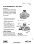
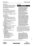
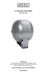
Type 912N-HNRUL
Instruction Manual
MCK-2286
July 2010
Type 912N-HNRUL Compressed Gas Non-Relief
Pressure Regulator
!
Warning
Failure to follow these instructions or
to properly install and maintain this
equipment could result in an explosion,
fire and/or chemical contamination
causing property damage and personal
injury or death.
Fisher® regulators must be installed,
operated, and maintained in accordance
with federal, state, and local codes,
rules and regulations, and Emerson
Process Management Regulator
Technologies, Inc. instructions.
For LP-Gas service, an approved
regulator (such as one listed by UL)
should be used or approved by the
Authority Having Jurisdiction.
Figure 1. Type 912N-HNRUL Regulator
If the regulator vents gas or a leak
develops in the system, service to the unit
may be required. Failure to correct trouble
could result in a hazardous condition.
Call a gas service person to service
the unit. Only a qualified person must
install or service the regulator.
Description
The Type 912N-HNRUL is a compressed gas
pressure regulator with the following features:
non-adjustable pressure setting, no-internal relief,
direct-operated, and spring-loaded.
The regulator is built to provide accurate and sensitive
control suited to a variety of applications.
Introduction
The Type 912N-HNRUL is UL listed as a Compressed
Gas Regulator for Hydrogen service.
Scope of the Manual
Specifications
Specifications for the Type 912N-HNRUL compressed
gas non-relief regulator are given on page 2.
D450223T012
This manual provides installation, maintenance and
parts ordering information for the Type 912N-HNRUL
non-relief pressure regulator (Figure 1) as used in
compressed gas applications.
www.fisherregulators.com
Type 912N-HNRUL
Specifications
Body Sizes and End Connection Style
Inlet: 1/4-inch NPT
Outlet: 3/8-inch NPT
Maximum Allowable Inlet Pressure(1)
250 psig (17,2 bar)
Orifice Size
0.073-inch (1,9 mm)
Outlet Pressure Standard Setpoint(1)
14-inches w.c. (35 mbar) Non-Adjustable
Non-Relief Performance
Sealing valve and closing cap can maintain 20 psig
(1,4 bar) pressure
Maximum Allowable Outlet Pressure(1)
Emergency Outlet Pressure:
20 psig (1,4 bar)
Recommended Outlet Pressure to Avoid
Internal Part Damage: 3 psi (0,21 bar differential)
above outlet pressure setting
Temperature Capabilities(1)
-20° to 160°F (-29° to 71°C)
Pressure Registration
Internal
Vent Size
1/8-inch NPT (standard)
Approximate Weight
1.30 pounds (0,6 kg)
1. The pressure/temperature limits in this Instruction Manual or any applicable standard limitation should not be exceeded.
Principle of Operation
Inlet pressure flows through the open orifice into the
regulator body and pressurizes the cavity formed
by the body and diaphragm assembly. When
downstream demand is reduced, the pressure under
the diaphragm increases. This pressure overcomes
the regulator setting (which is set by a spring) and
moves the diaphragm assembly upwards. This
upward motion is transferred to the lever which in
turn closes the disc holder/disc against the orifice
and reduces gas flow. If a higher volume flow rate
is demanded downstream, the pressure under the
diaphragm decreases. The control spring force
pushes the diaphragm assembly downward, lifting
the lever which moves the valve disc away from the
orifice allowing more gas into the downstream piping.
Installation
!
Warning
Personal injury or equipment damage
may result if the regulator is installed
where service conditions could exceed the
pressure or temperature specifications in
Specifications section.
The regulator must not be used for
hazardous gas service in a closed area
2
unless the vent is piped to a safe area.
The vent opening on the regulator or
the opening on the remote vent pipe
(if one is used) should be pointed down
to minimize clogging from collected
moisture, corrosive chemicals, and other
foreign material.
Overpressuring the downstream system
(and risk of explosion) could result from a
clogged vent.
Overpressuring any portion of a regulator
or associated equipment may cause
leakage, part damage, or personal injury
due to bursting of pressure-containing
parts or explosion of accumulated gas.
The Type 912N-HNRUL regulator has an outlet pressure
rating lower than the inlet pressure rating. Downstream
protection is required if the actual inlet pressure can
exceed the regulator outlet pressure rating or the
pressure rating of any downstream equipment.
Regulator operation within ratings does not preclude the
possibility of damage from external sources or from debris
in the lines. A regulator should be inspected for damage
periodically and after any overpressure condition.
Ensure that the regulator is undamaged and contains
no foreign material. Install the regulator so that the
flow through it leaves the outlet port (marked on the
Type 912N-HNRUL
body). The regulator may be installed in any position.
However, the spring case vent should be pointed
down. Spring case/vent orientation can be changed
by rotating the spring case with respect to the body.
For an indoor installation, if the regulator controls
a gas that is flammable or otherwise hazardous, a
spring case with the standard vent line should be
used so that the exhaust can be piped away. Provide
protection on a remote vent by installing a screened
vent cap into the remote end of the vent pipe. The
vent should be pointed down.
Maintenance
Regulator parts are subject to normal wear and
must be inspected and replaced as necessary. The
frequency of inspection depends on the severity of
service conditions or the requirements of local, state,
and federal rules and regulations.
To avoid personal injury or equipment
damage, do not attempt any
maintenance or disassembly without
first isolating the regulator from system
pressure and relieving all internal
pressure from the regulator.
Apply a good grade of pipe compound to the pipe
threads before making the connections. Install piping
into the 1/4-inch NPT inlet connection and the
3/8-inch NPT outlet connection.
Startup
Warning
!
Parts List
Key numbers are referenced in Figures 2 and 3.
Key Description With installation completed and downstream
equipment properly adjusted, slowly open the
upstream and downstream shutoff valves while
monitoring the regulator output pressure.
1
Note
The Type 912N-HNRUL has an adjusting
screw that is applied with a permanent bond.
!
Warning
For the Type 912N-HNRUL construction
never adjust the control spring to
produce an outlet pressure higher
than the outlet pressure range for
that particular spring. Doing so could
overpressure the system and cause
personal injury or equipment damage.
Body, Zinc
1/4 x 3/8-inch NPT
2
Spring Case
3
Closing Cap
4
Adjusting Screw
5
Regulator Spring, Steel 10
Diaphragm Plate, Zinc-plated Steel
11
Disc Holder
12 Fulcrum Rod, 302 Stainless steel
13
Machine Screw, Steel (2 required)
14
Machine Screw, Steel (6 required)
15 Diaphragm, Nitrile (NBR)
Spring Range: 12 to 24-inches w.c. (30 to 60 mbar)
16
Vent Screen, 304 Stainless steel
29 Disc, Fluorocarbon (FKM)
30 O-ring, Nitrile
31 Lock Nut, Zinc-plated Steel
32 Lock Washer, Plated Carbon Steel
33 Flat Washer, Steel
Shutdown
36 Pusher post, Aluminum
Close the nearest upstream shutoff valve, then close
the nearest downstream shutoff valve. Vent pressure
from the outlet of the regulator.
3
Type 912N-HNRUL
PB
4
3
2
30
32
5
33
31
16
10
1/8-inch NPT
L
14
13
23
top view
15
21
4
3
2
30
32
5
33
GE34610
10
16
1 36 11 12 29
14
13
Apply lubricant (L) or permanent bond (PB) as described
15
Figure 2. Type 912N-HNRUL Non-Relief
Pressure Regulator Assembly
31
15
32
1
31
11
12
29
33
10
GE35806
36
Figure 3. Type 912N-HNRUL Diaphragm Assembly
LP-Gas Equipment
Emerson Process Management
Regulator Technologies, Inc.
USA - Headquarters
McKinney, Texas 75069-1872 USA
Telephone: 1 (800) 558-5853
Telephone: 1 (972) 548-3574
For further information visit www.fisherregulators.com
The Emerson logo is a trademark and service mark of Emerson Electric Co. All other marks are the property of their prospective owners. Fisher is a mark owned by Fisher Controls, Inc., a
business of Emerson Process Management.
The contents of this publication are presented for informational purposes only, and while every effort has been made to ensure their accuracy, they are not to be construed as warranties or
guarantees, express or implied, regarding the products or services described herein or their use or applicability. We reserve the right to modify or improve the designs or specifications of such
products at any time without notice.
Emerson Process Management does not assume responsibility for the selection, use or maintenance of any product. Responsibility for proper selection, use and maintenance of any Emerson
Process Management product remains solely with the purchaser.
©Emerson Process Management Regulator Technologies, Inc., 2009, 2010; All Rights Reserved