1
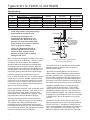
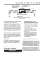
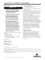
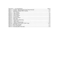
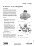
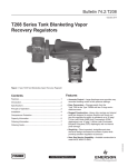
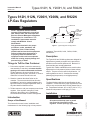
Types 912H, N, Y200H, N, and R922N
Instruction Manual
MCK-1112
February 2010
Types 912H, 912N, Y200H, Y200N, and R922N
LP-Gas Regulators
CLOSING CAP
Warning
Fisher® equipment must be installed,
operated, and maintained in accordance
with, federal, state, and local codes and
Emerson Process Management Regulator
Technologies, Inc. instructions. The
installation in most states must also
comply with NFPA No. 54 and
58 standards. Only personnel trained in the proper
procedures, codes, standards, and
regulations of the LP-Gas industry
should install and service this equipment.
Failure to follow these instructions or
to properly install and maintain this
equipment could result in an explosion
and/or fire causing property damage and
personal injury or death. Things to Tell the Gas Customer: 1. Point out the regulator’s vent to the customer (or
vent assembly or vent tube), and stress that this
opening must remain unobstructed at all times.
Tell the customer to be sure to check the vent
opening after a freezing rain, sleet storm, or snow to
make sure ice has not formed in the vent. 2. Show the customer the shutoff valve on the
container. The customer should close this valve
immediately if gas can be smelled, appliance pilot
lights fail to stay on or appear higher than usual, or
any other abnormal situation occurs. 3. Tell the customer to call your company to service the
regulator. If the regulator vents gas or a leak
develops in the system, only a qualified gas
serviceman should install or service the regulator.
VENT
(TYPES 912h
AND 912n)
VENT
(Types y200h
AND y200n)
OUTLET
INLET
Figure 1. Typical Regulator Configurations
regulators: Types 912N, 912H, Y200N, Y200H,
and R922N. Description The Types 912H and Y200H regulators are designed for
high-pressure (pounds per square inch) vapor service
and are not to be used for liquid service. Both are U.L.
listed, and they are normally painted red. Types 912N, Y200N, and R922N can be used for either
high-pressure or low-pressure (inches of water column)
service. They are not to be used for liquid service. “N”
suffix regulators are not U.L. listed and are normally painted gray (low-pressure) or red (high-pressure).
Specifications The Specifications table lists the specifications for the
regulators. Contact the factory if the regulators are to be
used on any service other than LP-Gas, Natural Gas, or
Air. Temperature limits are -20° to 160°F (-29° to 71°C).
Maximum inlet pressure is 250 psig (17,2 bar).
Installation !
Introduction Scope of the Manual This instruction manual covers installation and
maintenance for the following high or low-pressure
Warning
All vents must be kept open to permit
free flow of air into and out of the
regulator. Protect openings against the
www.fisherregulators.com/lp
D450027T012
!
Types 912H, N, Y200H, N, and R922N
Specifications
TYPE
size, inch fnpt
Inlet Connection
Outlet Connection
vent style
vapor capacity,
Btu/hr. propane
912H
1/4
1/4 or 3/8
High Pressure
Drilled and Screened
350 000
Y200H
1/4
3/8
High Pressure
Slot
350 000
912N
1/4
1/4 or 3/8
High or Low Pressure
Drilled and Screened
350 000
Y200N
1/4
3/8
High or Low Pressure
Slot
350 000
R922N
1/4. 1/2, or FEMALE POL
1/2
High or Low Pressure
3/4-inch FNPT and Screened
725 000
entrance of rain, snow, ice formation, paint, mud, insects, or any other foreign material that could plug the vent. LP-Gas may discharge to the
atmosphere through the vent. An
obstructed vent which limits air or
gas flow can cause abnormally high
pressure that could result in personal
injury or property damage. Never use a first-stage (pounds to
pounds) regulator on low pressure
(inches of water column) service
because personal injury or property
damage could occur. Make sure gas flow through the regulator is in the same
direction as the arrow on the body— ”Inlet” and “Outlet”
connections are clearly marked. The installation
should be adequately protected from vehicular traffic
and damage from other external sources. Install the
regulator so that any gas discharge through the vent or
vent assembly is over 3-feet (0,91 m) horizontally from
any building opening below the level of the discharge.
Install the regulator high enough above ground
level—at least 18-inches (457 mm) so that rain splatter
cannot freeze in the vent. Whether a protective hood
is used or not, do not install the regulator in a location
where there can be excessive water accumulation or
ice formation, such as directly beneath a downspout,
gutter, or roof line of a building. Before installing the regulator, check for damage which
might have occurred in shipment. Also check for and remove any dirt or foreign matter which may have
accumulated in the regulator body or pipeline. Apply
pipe compound to the male threads of the pipe. A hood or encasement should be used to protect the
Type Y200H or Y200N vent opening from the elements.
The regulator vent opening should slope down
sufficiently to allow any condensate to drain that may
have collected in the spring case. Be careful that the slot
in the hood for the regulator outlet piping does not extend
too far and expose the vent to the elements. 2
service
to appliances
vent
assembly
vent
LINE
vent opening must
be at least 3-FEET
(0,91 m) HORIZONTALLY
FROM ANY BUILDING
OPENING BELOW IT
BASEMENT
FROM FIRST-STAGE
REGULATOR
Figure 2. Typical Indoor Installation with
Vent Line and Vent Assembly
The Types 912H, 912N, and R922N can be installed
outdoors without a protective hood if their vent is
pointed verticaIly down. Horizontally mounted regulators, such as found on
single cylinder or tank installations, must be installed
beneath a protective cover. If possible, slope or turn
the vent down sufficiently to allow any condensation to
drain out of the spring case. Be careful that the slot in
the hood or cover for the regulator’s outlet piping does
not extend too far and expose the vent to the elements.
Regulators installed indoors are limited to 20 psig
(1,4 bar) maximum inlet pressure. Types Y200H,
Y200N, and most 912s must not be used on indoor
installations because a vent line to the outside of the
building cannot be installed. On regulators that have
a tapped vent (Type R922N and some 912s), use pipe
or tubing equal in size to the regulator’s vent for the
vent line.
To install the vent line, remove the vent screen and
apply a good grade of pipe dope to the male threads of
the line, see Figure 2. Vent piping or tubing must not
restrict the flow passage of the regulator’s internal relief
valve. A vent assembly, such as Fisher® Type Y602,
should be used on the end of the vent line. The same
Types 912H, N, Y200H, N, and R922N
GRADE AROUND DOWNWARD ANd
aWAY AROUND HOUSING DOME. THIS PREVENTS WATER COLLECTING AND RUNNING INTO OR STANDING AROUND HOUSING DOME.
END OF REGULATOR VENT TUBE
LOCATED AT TOP INSIDE OF HOUSING DOME COVER.
2-INCH (51 mm) MINIMUM
REGULATOR ADJUSTMENT CLOSURE CAP MUST BE TIGHT.
WATER MARK LEFT IN HOUSING DOME AT LEVEL ABOVE REGULATOR VENT OR END OF VENT TUBE REQUIRES REPLACEMENT OF REGULATOR. THEN CORRECT INSTALLATION. Figure 3. Regulators Installed on Underground Installations
Require a Vent Tube
installation precautions apply to vent assemblies as the
integral regulator vents covered previously.
Underground container systems require a vent tube to prevent water from entering the regulator spring case, see Figure 3. Only the Types R922N and some 912s
can be used on underground installations because of the
need to use a vent tube. Remove the vent screen and
install the vent tube, such as a Fisher® Type P203. The
vent tube must be run from the regulator vent to above
the maximum water tube. The vent tube opening must
terminate at the extreme top inside of the dome cover.
Make sure the regulator’s closing cap is on tightly, and maintain drainage away from the dome at all times.
For further information on underground installations,
write for a copy of “Underground LP-Gas Systems:
Suggested Installation, Inspection,” available from the
National LP-Gas Association, 1301 W. 22nd St., Oak
Brook, IL 60521.
Adjustment Each regulator’s outlet pressure is factory-set. If
it becomes necessary to increase outlet pressure,
remove the closing cap, Figure 1, and turn the
adjusting screw clockwise. Turn the adjusting screw
counterclockwise to decrease the outlet pressure.
A pressure gauge is needed to determine the
regulator’s outlet setting after adjustment. Always
replace the closing cap after adjustment. Overpressure Protection !
Warning
Personal injury or system damage may
result if these regulators are installed
without appropriate overpressure
protection on final-stage service. Outlet
pressures greater than 5 psig (0,35 bar)
above the setpoint may cause damage
to regulator parts, leaks in the regulator,
or personal injury due to bursting of
pressure-containing parts or explosion
of accumulated gas. If the regulator is exposed to an
overpressure condition, it must be
inspected for any damage that may
have occurred.
Large volumes of gas may discharge through the regulator vent during
internal relief valve operation which
can result in fire or explosion from
accumulated gas.
All the regulators have an internal relief valve
that opens when downstream pressure reaches
approximately 13 psig (0,90 bar) on regulators set at
10 psig (0,70 bar) or approximately 1 psig (0,07 bar)
on regulators set at 11-inches w.c. (0,03 mbar). When
the internal relief valve opens, gas escapes to the
atmosphere through the regulator’s vent. The internal
relief valve gives overpressure protection against
excessive build-up resulting from seat leakage due to
worn parts or chips of foreign material on the orifice.
Some type of external overpressure protection must
be provided if inlet pressure will be high enough to
damage downstream equipment on final-state service.
Common methods of external overpressure protection
include relief valves and series regulation.
3
Types 912H, N, Y200H, N, and R922N
Maintenance !
Warning
To avoid personal injury or equipment
damage, do not attempt any maintanance
or disassembly without first isolating
the regulator from system pressure and
relieving all internal pressure. Regulators that have been disassembled for repair must be tested for proper
operation before being returned to
service. Only parts manufactured by
Fisher® should be used for repairing
Fisher regulators. Relight pilot lights
according to normal startup procedures.
Due to normal wear or damage that
may occur from external sources,
these regulators must be inspected and
maintained periodically. The frequency
of inspection and replacement of the
regulators depends upon the severity of
service conditions or the requirements of
local, state, and federal regulations. Even
under ideal conditions, these regulators
should be replaced after 15 years from
the date of manufacture or sooner should
inspection reveal the need. Visually inspect the regulator each time a gas delivery
is made for: 1. Improper installation. 2. Plugged or frozen vent. 3. Wrong regulator or no regulator in the system.
4. Internal or external corrosion.
5. Age of the regulator. 6. Any other condition that could cause the uncontrolled escape of gas. Failure to do the above could result in personal injury or property damage. Make sure the regulator vent, vent assembly, or vent tube does not become plugged by mud, insects, ice,
snow, paint, etc. The vent screen aids in keeping the
vent from becoming plugged, and the screen should be clean and properly installed. Replace any regulators that have had water in their
spring case or show evidence of external or internal
corrosion. Checking for internal corrosion may
require complete removal of the adjusting screw
and shutdown of the gas system. Closely examine
regulators directly connected to the container valve by
means of a solid POL adapter (horizontal mounting) for
signs of corrosion. Correct any improper installations.
Older regulators are more likely to catastrophically fail because of worn or corroded parts. Replace regulators over 15 years of age; other service or
environmental conditions may dictate replacement of
the regulator before it becomes 15 years old, refer to
Fisher Bulletin LP-32.
Regulator Repair Regulators that have been disassembled for repair must be tested for proper operation before being returned to service. Fisher Type Y499-2 test rack
can be furnished for this purpose. Only parts
manufactured by Fisher should be used for the repair of Fisher regulators. Be sure to give the complete
type number of the regulator when corresponding with
the factory.
LP-Gas Equipment
Emerson Process Management
Regulator Technologies, Inc.
USA - Headquarters
McKinney, Texas 75069-1872 USA
Telephone: 1 (800) 558-5853
Telephone: 1 (972) 548-3574
For further information visit www.fisherregulators.com/lp
The Emerson logo is a trademark and service mark of Emerson Electric Co. All other marks are the property of their prospective owners. Fisher is a mark owned by Fisher Controls, Inc., a
business of Emerson Process Management.
The contents of this publication are presented for informational purposes only, and while every effort has been made to ensure their accuracy, they are not to be construed as warranties or
guarantees, express or implied, regarding the products or services described herein or their use or applicability. We reserve the right to modify or improve the designs or specifications of such
products at any time without notice.
Emerson Process Management does not assume responsibility for the selection, use or maintenance of any product. Responsibility for proper selection, use and maintenance of any Emerson
Process Management product remains solely with the purchaser.
©Emerson Process Management Regulator Technologies, Inc,. 1986, 2010; All Rights Reserved