1
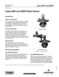
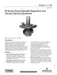
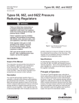
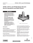
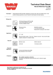
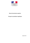
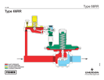
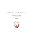
Bulletin 71.4:66
November 2009
Types 66R and 66RR Low-Pressure Relief Valves
W1908
W1953
TYPE 66R RELIEF VALVE
TYPE 66RR RELIEF VALVE
Figure 1. Typical Constructions
Features
Types 66R and 66RR low-pressure throttling relief
valves(1) are used to help protect a system against
overpressure, or to maintain an inlet or backpressure.
The standard Type 66R direct-operated construction
is used for 2-inches w.c. to 2 psig (5 mbar to 0,14 bar)
set pressure ranges, while the standard Type 66RR
pilot-operated construction with Type Y695RR pilot is
used for 4-inches w.c. to 4.5 psig (10 mbar to 0,31 bar)
set pressure ranges. However, higher set pressure
ranges are available with optional springs, diaphragm
plates, and other internal parts.
Standard Type 66R relief valves have internal
registration through a stem guide (Figure 2) that
reduces the need for control line piping, while cast iron
body Type 66R relief valves additionally are available
with a sealing diaphragm and a tapped connection
boss on the diaphragm case for external registration
that requires a separate control line. All Type 66RR
relief valves come standard with internal registration in
the main valve body and tapped connection bosses on
the pilot casings for external registration that requires
a separate control line.
• Seat Protection without Sacrifice in Shutoff Capability—Retainer (Figure 2) in standard
valve plug assembly closes against seat ring
before assembly can overtravel and thus
overcompress O-ring.
• Application Flexibility—Steel bodies are
available for increased resistance to piping
stresses or whenever dictated by local codes.
External registration is optional with all cast iron
bodies for wherever a remote control line is
required. These relief valves can be used for
vacuum service in both standard and special
versions, since vacuum service capacity is
comparable with relief service capacity.
• Severe Service Capability—Fluorocarbon (FKM)
soft parts and stainless steel metal trim parts are
available for high-temperatures and/or special
gases. Optional all-metal seats lessen O-ring seat
erosion problems with coke gas or other corrosive
applications and have knife-edged guides on their
valve plug skirts to help prevent particle
accumulation with dirty service.
1. Throttling relief valve defined in ANSI standard B95.1-1972. Not all codes or regulations permit these valves to be used as final overpressure protection devices.
www.fisherregulators.com
D100152X012
Introduction
Bulletin 71.4:66
Specifications
Body Sizes and End Connection Styles
TYPES
66R,
66RR
NOMINAL
BODY SIZE,
NPS (DN)
END CONNECTION
STYLES AND RATINGS(1)
Standard Cast
Iron Body
Optional Steel
Body
2 (50)
NPT or
CL125 FF flanged
NPT, CL150 RF,
and CL300 RF
flanged
3, 4 (80, 100)
CL125 FF flanged
CL150 RF flanged
Maximum Relief (Inlet) Pressure(1)
Type 66R: 8 psig (0,55 bar), including build-up
Type 66RR: 10 psig (0,69 bar), including build-up
Standard Relief Set Pressure Ranges
Type 66R: See Table 1
Type 66RR: See Table 2
Orifice Sizes
NPS 2 (DN 50) Body: 2-inch (51 mm)
NPS 3 (DN 80) Body: 3-inch (76 mm)
NPS 4 (DN 100) Body: 4-inch (102 mm)
Type Y695RR Pilot and Mounting Parts
(Type 66RR Only)
Body: Ductile iron (standard) or steel
Spring Case: Cast iron
Lower Casing Assembly: Cast iron and
stainless steel
Lower Diaphragm Plate, Stainless Steel Trim Only: Stainless steel
Diaphragm: Nitrile (NBR) (standard) or
Fluorocarbon (FKM) (high-temperature)
Lower Spring Seat: Zinc-plated steel
Back Disk Spring: Stainless steel
Pressure Setting Spring: Zinc-plated or
cadmium-plated steel
Orifice and Disk Holder: Stainless steel
Disk: Nitrile (NBR) (standard) or
Fluorocarbon (FKM) (high-temperature)
Valve Stem: Stainless steel
Pusher Post: Stainless steel
Lever Assembly: Stainless steel
Mounting Bar, Fittings, and Bolting: Steel
Temperature Capabilities
Typical Performance Curves
See Figures 3 and 4
Relief Capacities
See Tables 4 and 5
Construction Materials
Complete Relief Valve (Type 66R)
or Main Valve (Type 66RR)
Body and Body Piping: Cast iron (standard) or steel
Spring Case: Steel
Diaphragm Case, Diaphragm Plates, Bottom
Flange, Spring, and Bolting: Plated Steel
Diaphragm Spacer when Used: Zinc-plated steel
Diaphragms, and Valve Plug O-Ring and Spring Case Gasket when Used: Nitrile (NBR) (standard)
or Fluorocarbon (FKM) (high-temperature)
Bottom Flange and Stem Gaskets: Composition
Diaphragm Case and Closing Cap
Gaskets: Neoprene (CR)
Sealing Washer and Spring Case Drive Screw when Used: Carbon steel
Type Y602-10 Vent Assembly when Used:
Zinc/stainless steel/Monel®
Snap Ring when Used: Bronze
Closing Cap, Adjusting Screw, and
Spring Seats: Zinc
Flapper Valve when Used: Brass
Seat Ring: Bronze (standard) or stainless steel
Standard Elastomers
-20° to 180°F (-29° to 82°C)
High-Temperature Elastomers
0° to 350°F (-18° to 177°C)
IEC Sizing Coefficient
See Table 3
Pressure Registration
Type 66R:
Internal (standard) or external
Type 66RR:
External on pilot and internal in main valve
Pressure Connections
Type 66R
Control Line (if used): 3/4 NPT standard
Spring Case Vent: 3/4 NPT standard with removable Type Y602-10 vent assembly
Type 66RR
Pilot Body: 3/4 NPT standard
Pilot Lower Casing Assembly: 1/2 NPT standard
Pilot Spring Case: 1/2 NPT standard
1. The pressure/temperature limits in this Bulletin and any applicable ASME standard should not be exceeded.
2. Monel® is a mark owned by Special Metals Corporation.
- continued 2
Bulletin 71.4:66
Specifications (continued)
Approximate Weights
NPS 2 (DN 50) Body
NPT: 50 pounds (23 kg) for Type 66R or
65 pounds (29 kg) for Type 66RR
Flanged Ends: 55 pounds (25 kg) for Type 66R or
70 pounds (32 kg) for Type 66RR
NPS 3 (DN 80) Body: 100 pounds (45 kg) for
Type 66R or 115 pounds (52 kg) for Type 66RR
NPS 4 (DN 100) Body: 155 pounds (70 kg) for
Type 66R or 170 pounds (77 kg) for Type 66RR
Options
Special springs and other internal parts for
Type 66R set pressures from 1.5 to 5 psig (0,10 to
0,34 bar) and Type 66RR set pressures from
3.8 to 7 psig (0,01 to 0,48 bar); control line
connection for cast iron Type 66R; all-metal seats for NPS 2 (DN 50) cast iron Type 66R
pilot
control
spring
Fixed
restriction
Pilot
Valve Disk
diaphragm
type y695rr
pilot
main valve
Diaphragm
o-ring
retainer
Stem guide
valve Stem
o-ring
M1041
M1056
valve plug
skirt
standard type 66r relief
valve with internal
registration
main valve
valve plug
Skirt
type 66rr relief valve
inlet (controlled) pressure
outlet pressure
atmospheric pressure
loading pressure
Figure 2. Operational Schematics
3
Bulletin 71.4:66
Table 1. Spring Selection for Type 66R Relief Set Pressure Ranges
BODY
SIZE,
NPS (DN)
CONSTRUCTION
RELIEF SET PRESSURE RANGE
SPRING
PART
NUMBER
SPRING COLOR
SPRING
WIRE
DIAMETER,
INCHES (mm)
SPRING
FREE
LENGTH,
INCHES (mm)
Standard
2 to 8-inches w.c. (5 to 20 mbar)
6 to 16-inches w.c. (15 to 40 mbar)
11-inches w.c. to 1 psig (27 mbar to 0,07 bar)
0.75 to 1.5 psig (0,05 to 0,10 bar)
1 to 2 psig (0,07 to 0,14 bar)
1D765427012
1D765527012
1D765627032
1D765727032
1D765827032
Pink Stripe
Blue Stripe
Green Stripe
Red Stripe
Unpainted
0.120 (3,05)
0.138 (3,51)
0.177 (4,50)
0.207 (5,26)
0.225 (5,72)
6.00 (152)
6.00 (152)
6.00 (152)
6.09 (155)
6.00 (152)
Special
1.5 to 3 psig (0,10 to 0,21 bar)
3 to 5 psig (0,21 to 0,34 bar)
1D962627032
1N506427142
Unpainted
Black Stripe
0.262 (6,66)
0.283 (7,19)
6.25 (159)
6.31 (160)
Standard
2 to 8-inches w.c. (5 to 20 mbar)
6 to 16-inches w.c. (15 to 40 mbar)
11-inches w.c. to 1 psig (27 mbar to 0,07 bar)
0.75 to 1.5 psig (0,05 to 0,10 bar)
1 to 2 psig (0,07 to 0,14 bar)
1D770727012
1D770827032
1D765727032
1D765827032
1D770927032
Olive Green Stripe
Red and Yellow Stripe
Red Stripe
Unpainted
Blue and Yellow Stripe
0.135 (3,43)
0.162 (4,12)
0.207 (5,26)
0.225 (5,72)
0.283 (7,19)
6.00 (152)
6.00 (152)
6.09 (155)
6.00 (152)
6.06 (154)
Special
1.5 to 3 psig (0,10 to 0,21 bar)
3 to 5 psig (0,21 to 0,34 bar)
1E204427032
1N506527142
White and Red Stripe
Brown and Purple Stripe
0.306 (7,77)
0.363 (9,22)
6.38 (162)
6.38 (162)
Standard
2 to 8-inches w.c. (5 to 20 mbar)
6 to 16-inches w.c. (15 to 40 mbar)
11-inches w.c. to 1 psig (27 mbar to 0,07 bar)
0.75 to 1.5 psig (0,05 to 0,10 bar)
1 to 2 psig (0,07 to 0,14 bar)
1D771027012
1D771127032
1D527627032
1D771227032
1D771327032
Orange and Yellow Stripe
Light Blue Stripe
Gray and White Stripe
Pink and Blue Stripe
Silver Stripe
0.135 (3,43)
0.177 (4,50)
0.225 (5,72)
0.262 (6,66)
0.283 (7,19)
7.75 (197)
7.94 (202)
7.75 (197)
7.75 (197)
7.75 (197)
Special
1.5 to 3 psig (0,10 to 0,21 bar)
1E204527032
Pink Stripe
0.331 (8,41)
7.53 (191)
2 (50)
3 (80)
4 (100)
Table 2. Type Y695RR Pilot Control Spring Selection
PILOT CONTROL SPRING
MAIN VALVE
CONSTRUCTION
RELIEF SET PRESSURE RANGE
Part Number
Color Code
Wire Diameter,
Inches (mm)
Free Length,
Inches (mm)
Standard
4 to 9-inches w.c. (10 to 22 mbar)(1)
5 to 15-inches w.c. (12 to 37 mbar)(1)
12 to 28-inches w.c. (30 to 70 mbar)(1)
0.9 to 2.5 psig (0,06 to 0,17 bar)
1.3 to 4.5 psig (0,09 to 0,31 bar)
1B653827052
1B653927022
1B537027052
1B537127022
1B537227022
Red
Cadmium
Yellow
Light green
Light blue
0.085 (2,16)
0.105 (2,67)
0.114 (2,90)
0.156 (3,96)
0.187 (4,75)
3.625 (92,1)
3.750 (95,3)
4.188 (106)
4.060 (103)
3.938 (100)
Special
3.8 to 7 psig (0,26 to 0,48 bar)
1B537327052
Black
0.218 (5,54)
3.980 (101)
1. Published ranges are with the spring case pointed up.
Principle of Operation
Type 66R Relief Valve
Inlet pressure registers under the diaphragm and is
opposed by the spring (Figure 2). When the inlet
pressure increases above the spring setting, the valve
plug opens in a throttling manner and relieves the
inlet pressure. As inlet pressure drops back to set
pressure, the spring closes the valve plug.
Type 66RR Relief Valve
Inlet pressure registers on the bottom of the pilot
diaphragm through the upstream control line and
bleeds through a fixed restriction in the pilot (Figure 2)
to provide loading pressure that helps the main valve
spring keep the main valve plug tightly shutoff. When
inlet pressure exceeds the setting of the pilot spring,
4
the pilot diaphragm moves upward, opening the pilot
valve disk and relieving some of the pressure from the
top of the main valve diaphragm. At the same time,
the inlet pressure increase registers on the bottom of
the main valve diaphragm.
The pressure differential acting on the main valve
diaphragm moves this diaphragm upward, opening
the main valve. Further increases in inlet pressure
continue to open the pilot valve disk and the main
valve plug. When inlet pressure returns to the pilot
control spring setting, the pilot disk closes, allowing
inlet pressure to load the top of the main valve
diaphragm through the fixed restriction.
This equalizes the pressures acting on this diaphragm,
and the main valve spring closes the main valve plug.
Bulletin 71.4:66
Table 3. IEC Sizing Coefficients
BODY SIZE, NPS (DN)
XT
FD
2 (50)
3 (80)
FL
Km
0.89
0.79
0.35
0.78
0.34
4 (100)
0.30
Table 4. Selected Type 66R Relief Capacities in SCFH (Nm3/h) of 0.6 Specific Gravity Natural Gas(1)
BODY SIZE,
NPS (DN)
BUILD-UP OVER RELIEF SET PRESSURE
SPRING
PART
NUMBER
RELIEF
SET
PRESSURE
1 (2)
3 (7)
5 (12)
1D765427012
5-inches w.c.
(12 mbar)
3300
(88,4)
8500
(228)(2)
9500
(255)
10 000
(268)
12 500
(335)
----
1D765527012
10-inches w.c.
(25 mbar)
----
7300
(196)
10 800
(289)
12 000
(322)(2)
14 000
(375)
1D765627032
14-inches w.c.
(35 mbar)
----
----
8200
(220)
11 500
(308)
1D765727032
1 psig
(0,07 bar)
----
----
----
1D765827032
1.5 psig
(0,10 bar)
----
----
1D962627032
2 psig
(0,14 bar)
----
1D770727012
5-inches w.c.
(12 mbar)
1D770827032
Inches w.c. (mbar)
Psig (bar)
1.5 (0,10)
2 (0,14)
3 (0,21)
----
----
----
----
15 300
(410)
----
----
----
----
15 000
(402)(2)
16 800
(450)
18 500
(496)
----
----
----
7750
(208)
16 700
(448)
18 500
(496)(2)
20 000
(536)
24 000
(643)
----
----
----
----
15 000
(402)
21 000
(563)
24 000
(643)(2)
26 000
(697)
29 000
(777)
----
----
----
----
----
17 000
(456)
23 000
(616)
29 000
(777)(2)
31 000
(831)
35 000
(938)
5500
(147)
18 500
(496)(2)
20 000
(536)
22 000
(590)
27 000
(724)
----
----
----
----
----
10-inches w.c.
(25 mbar)
----
11 800
(316)
21 500
(576)
26 000
(697)(2)
31 000
(831)
34 000
(911)
----
----
----
----
1D765727032
14-inches w.c.
(35 mbar)
----
----
11 500
(308)
17 500
(469)
33 000
(884)(2)
36 000
(965)
40 000
(1072)
----
----
----
1D765827032
1 psig
(0,07 bar)
----
----
----
15 000
(402)
29 000
(777)
41 000
(1099)(2)
46 000
(1233)
52 000
(1394)
----
----
1D770927032
1.5 psig
(0,10 bar)
----
----
----
----
18 000
(482)
30 000
(804)
44 000
(1179)
57 000
(1528)(2)
62 000
(1662)
----
1E204427032
2 psig
(0,14 bar)
----
----
----
----
----
27 000
(724)
39 000
(1045)
60 000
(1608)
67 000
(1796)(2)
76 000
(2037)
1D771027012
5-inches w.c.
(12 mbar)
10 300
(276)
28 000
(750)(2)
32 000
(858)
34 000
(911)
41 000
(1099)
----
----
----
----
----
1D771127032
10-inches w.c.
(25 mbar)
----
22 000
(590)
36 000
(965)
39 000
(1045)(2)
46 000
(1233)
52 000
(1394)
----
----
----
----
1D527627032
14-inches w.c.
(35 mbar)
----
----
24 000
(643)
35 000
(938)
50 000
(1340)(2)
55 000
(1474)
61 000
(1635)
----
----
----
1D771227032
1 psig
(0,07 bar)
----
----
----
21 000
(563)
50 000
(1340)
65 000
(1742)(2)
70 000
(1876)
78 000
(2090)
----
----
1D771327032
1.5 psig
(0,10 bar)
----
----
----
----
36 000
(965)
60 000
(1608)
78 000
(2090)
86 000
(2305)(2)
95 000
(2546)
----
1E204527032
2 psig
(0,14 bar)
----
----
----
----
----
40 000
(1072)
60 000
(1608)
90 000
(2412)
102 000
(2734)(2)
115 000
(3082)
2 (50)
3 (80)
4 (100)
0.25 (0,02) 0.5 (0,03) 0.75 (0,05) 1 (0,07)
1. See “Capacity Information” section for conversion to equivalent capacities of other gases and/or normal cubic meters per hour.
2. Valve wide-open
5
Bulletin 71.4:66
Table 5. Selected Type 66RR Relief Capacities in SCFH (Nm3/h) of 0.6 Specific Gravity Natural Gas(1)
BODY SIZE,
NPS (DN)
TYPE
Y695RR
PILOT
CONTROL
SPRING
RELIEF
SET
PRESSURE
Red
BUILD-UP OVER RELIEF SET PRESSURE
Inches w.c. (mbar)
Psig (bar)
1 (2)
3 (7)
5 (12)
1 (0,07)
1.5 (0,10)
2 (0,14)
3 (0,21)
5-inches w.c.
(12 mbar)
6200
(166)(2)
7300
(196)
8250
(221)
9000
(241)
11 600
(311)
----
----
----
----
----
Cadmium
10-inches w.c.
(25 mbar)
8750
(235)(2)
9550
(256)
10 200
(273)
10 800
(289)
13 000
(348)
15 100
(405)
----
----
----
----
Yellow
14-inches w.c.
(35 mbar)
10 300
(276)(2)
11 100
(297)
11 700
(314)
12 400
(332)
14 300
(383)
16 100
(431)
17 900
(480)
----
----
----
Light green
1 psig
(0,07 bar)
14 400
(386)(2)
15 200
(407)
15 700
(421)
16 100
(431)
17 700
(474)
19 200
(515)
20 600
(552)
23 200
(622)
----
----
Light green
1.5 psig
(0,10 bar)
----
18 000
(482)
18 500
(496)
19 000
(509)
20 500
(549)
22 000
(590)
23 500
(630)
26 000
(697)
28 000
(750)
----
Light blue
2 psig
(0,14 bar)
----
20 000
(536)
20 500
(549)
21 000
(563)
22 500
(603)
24 000
(643)
25 500
(683)
28 000
(750)
30 000
(804)
33 000
(884)
Red
5-inches w.c.
(12 mbar)
15 700
(421)(2)
18 600
(498)
21 200
(568)
23 000
(616)
29 400
(788)
----
----
----
----
----
Cadmium
10-inches w.c.
(25 mbar)
22 700
(608)(2)
24 800
(665)
26 600
(713)
28 400
(761)
34 000
(911)
38 700
(1037)
----
----
----
----
Yellow
14-inches w.c.
(35 mbar)
16 100
(431)(2)
28 200
(756)
29 700
(796)
31 500
(844)
36 400
(976)
42 000
(1126)
45 500
(1219)
----
----
----
Light green
1 psig
(0,07 bar)
35 600
(954)(2)
37 200
(997)
38 200
(1024)
39 800
(1067)
44 000
(1179)
48 000
(1286)
51 500
(1380)
58 800
(1576)
----
----
Light green
1.5 psig
(0,10 bar)
----
45 000
(1206)
46 000
(1233)
47 200
(1265)
50 000
(1340)
54 000
(1447)
56 000
(1501)
59 900
(1605)
62 000
(1662)
----
Light blue
2 psig
(0,14 bar)
----
51 000
(1367)
52 000
(1394)
53 300
(1428)
56 000
(1501)
59 500
(1595)
62 000
(1662)
64 000
(1715)
66 000
(1769)
72 000
(1930)
Red
5-inches w.c.
(12 mbar)
25 500
(683)(2)
30 000
(804)
33 600
(900)
36 900
(989)
45 400
(1217)
----
----
----
----
----
Cadmium
10-inches w.c.
(25 mbar)
35 100
(941)(2)
38 200
(1024)
41 300
(1107)
43 800
(1174)
52 600
(1410)
59 800
(1603)
----
----
----
----
Yellow
14-inches w.c.
(35 mbar)
41 300
(1107)(2)
43 800
(1174)
46 500
(1246)
49 000
(1313)
56 700
(1520)
66 500
(1782)
70 600
(1892)
----
----
----
Light green
1 psig
(0,07 bar)
57 400
(1538)(2)
59 300
(1589)
62 000
(1662)
63 200
(1694)
65 000
(1742)
67 700
(1814)
77 800
(2085)
90 000
(2412)
----
----
Light green
1.5 psig
(0,10 bar)
----
64 400
(1726)
66 900
(1793)
67 900
(1820)
69 500
(1863)
72 000
(1930)
86 000
(2305)
93 000
(2492)
96 000
(2573)
----
Light blue
2 psig
(0,14 bar)
----
69 500
(1863)
72 000
(1930)
73 000
(1956)
74 600
(1999)
77 000
(2064)
90 000
(2412)
95 000
(2546)
100 000
(2680)
110 000
(2948)
2 (50)
3 (80)
4 (100)
0.25 (0,02) 0.5 (0,03) 0.75 (0,05)
1. See “Capacity Information” section for conversion to equivalent capacities of other gases and/or normal cubic meters per hour. Shaded capacities are approximate.
2. Valve wide-open
6
Bulletin 71.4:66
NPS 2 (DN 50)
body
NPS 3 (DN 80)
body
0,20
NPS 4 (DN 100)
body
0,15
2
0,10
1
inlet pressure
(bar)
inlet pressure
(psig)
3
0,05
0
8
(0,2)
16
(0,4)
24
(0,6)
32
(0,9)
40
(1,1)
48
(1,3)
56
(1,5)
64
(1,7)
72
(1,9)
88
(2,4)
80
(2,1)
flow rate in thousands of scfh (Nm3/h)
of 0.6 specific gravity natural gas
BJ9212-A
A2561
NOTE:
see “capacity information” section for conversion to equivalent capacities of other
gases and/or cubic meters per hour. each curve represents a different body size as
marked. all measurements made at 1 psig (0,07 bar) relief set pressure.
Figure 3. Typical Performance Curves for Standard Type 66R Relief Valve
40
100
80
32
NPS 4
(DN 100)
type 66r
70
60
24
50
40
16
NPS 4 (DN 100)
type 66rr
8
inlet pressure (mbar)
inlet pressure (inches w.c.)
90
30
20
10
0
0
18
(0,5)
36
(1,0)
54
(1,4)
72
(1,9)
flow rate in thousands of scfh (Nm3/h)
of 0.6 specific gravity natural gas
NOTE:
see “capacity information” section for conversion to equivalent capacities of other gases and/or cubic
meters per hour. each curve represents a different body size as marked. all measurements made at
14-inches w.c. (35 mbar) relief set pressure; additionally, type 66rr main valve spring set at 2-inches w.c. (5 mbar)
A0902-1
Figure 4. Typical Performance Curves for NPS 4 (DN 100) Types 66R and 66RR Relief Valves
7
Bulletin 71.4:66
control line
gas to
fuel system
compressor
digester
tank
BJ8921-C
A2562
Figure 5. Type 66R Relief Valve Installation at Outlet of Sewage Treatment Plant Digester Tank
control line
atmosphere only
into diaphragm
case vent
vacuum
being
limited
AV9712-D
A2564
positive pressure
or atmosphere,
or a lesser vacuum
than the vacuum
being limited
vacuum pump
Figure 6. Type 66RR Relief Valve Installation in Vacuum Breaker System
Installation
Capacity Information
A Type 66R or 66RR relief valve should be installed
horizontally with the diaphragm casings vertical above
the body. Other orientations will change the relief set
pressure and set pressure range due to the weight of
the internal parts. Typical installations are shown in
Figures 5 and 6.
Table 4 gives Type 66R and Table 5 gives Type 66RR
flow capacities at selected set pressures. Flows are
in scfh (60°F and 14.7 psia) of 0.6 specific gravity
natural gas at 60°F. To determine the equivalent
capacities for air, propane, butane, or nitrogen, multiply
the Table 4 or 5 capacity by the following appropriate
conversion factor: 0.775 for air, 0.628 for propane,
0.548 for butane, or 0.789 for nitrogen. For gases of
other specific gravities, multiply the given capacity by
0.775 and divide by the square root of the appropriate
specific gravity. Then, if capacity is desired in normal
cubic meters per hour (Nm3/h) at 0°C and 1,01325 bar,
multiply scfh by 0.0268.
Connection locations and dimensions are both shown
in Figure 7.
8
Bulletin 71.4:66
C
E
3/4 NPT
control line
connection
(when used)
G
A/2
A
type 66r
F
1/4 npt vent
pilot
exhaust
3.69
(94)
D
1/2 npt
control line
connection
e
g
A/2
A
type 66rr with type y695rr pilot
A
BODY
SIZE,
NPS (DN)
NPT
Cast
Iron
Body
NPT
Steel
Body
Inch mm Inch mm
2 (50)
3 (80)
4 (100)
inches
(mm)
C
AD6045-D
21A9672-A
B1410
C
CL125 FF
Cast Iron
or CL150
RF Steel
Body
Inch
CL300 RF
Steel
Body
E
G
D
F
(TYPE 66RR
(TYPE 66RR
Type 66R Type 66RR
Type 66R Type 66RR
ONLY)
ONLY)
mm Inch mm Inch mm Inch mm Inch mm
7.25 184 9.25 235 10.00 254 10.50 267 13.88 353 22.12 562 4.50
....
....
....
.... 11.75 298 ....
.... 16.00 406 24.19 614 5.50
....
....
....
.... 13.88 353 ....
.... 18.00 457 25.94 659 6.25
Inch mm Inch mm Inch
NPT
Steel
Body
All
Others
mm Inch mm Inch mm
114 11.75 298 12.69 322 15.19 386
140 13.00 330 14.12 359 16.19 411
159 15.88 403 15.25 387 16.94 430
3.31 84 3.25 83
.... .... 4.62 117
.... .... 5.38 137
Figure 7. Dimensions
9
Bulletin 71.4:66
Ordering Information
When ordering, specify:
Application
1. Composition and specific gravity of gas (including
chemical analysis if possible)
2. Range of temperatures, flowing inlet pressures
(maximum, minimum, nominal), and
pressure drops
3. Desired relief set pressure or set pressure range.
4. Range of flow rates (minimum controlled, maximum, normal)
5. Piping size(s)
Construction
Refer to the page 2 “Specification section” and to
each referenced table; specify the desired selection
whenever there is a choice to be made. Always be
sure to specify the relief valve type number.
Ordering Guide
Type (Select One)
66R, maximum inlet pressure: 8 psig (0,55 bar)
66RR, maximum inlet pressure: 10 psig (0,69 bar)
Body Size (Select One)
NPS 2 (DN 50)
NPS 3 (DN 80)
NPS 4 (DN 100)
Body Material and End Connection Style
(Select One)
Cast Iron
NPT - 2-inch only***
CL125 FF***
Steel
NPT - 2-inch only**
CL150 RF**
CL300 RF**
PN 16/25/40**
Main Valve Diaphragm, Valve Plug, and O-ring
(Select One)
Nitrile (NBR)***
Flourocarbon (FKM)***
Optional Polytetrafluoroethylene (PTFE)
Diaphragm Protector (Select)
Yes***
Seat Ring Material (Select One)
Bronze***
316*
Pilot Body Material (Select One for
Type 66RR Only)
Cast Iron***
CF8M Stainless steel*
Pilot Diaphragm and Disk (Select One for
Type 66RR Only)
Nitrile (NBR)***
Fluorocarbon (FKM)***
Main Valve Diaphragm Case Material (Select One)
10
Steel***
304 Stainless steel**
- continued -
Bulletin 71.4:66
Ordering Guide (continued)
Set Pressure Ranges (Select One)
Type 66R
2 to 8-inches w.c. (5 to 20 mbar)***
6 to 16-inches w.c. (15 to 40 mbar)***
11-inches w.c. to 1 psig (27 to 69 mbar)***
0.75 to 1.5 psig (52 to 103 mbar)***
1 to 2 psig (69 to 138 mbar)***
1.5 to 3 psig (103 to 207 mbar)***
3 to 5 psig (207 to 345 mbar)***
Type 66RR
4 to 9-inches w.c. (10 to 22 mbar), Red***
5 to 15-inches w.c. (12 to 37 mbar), Cadmium***
12 to 28-inches w.c. (30 to 70 mbar), Yellow***
0.9 to 2.5 psig (62 to 172 mbar), Light Green***
1.3 to 4.5 psig (90 to 310 mbar), Light Blue***
3.8 to 7 psig (262 to 483 mbar), Black***
Replacement Parts Kit (Optional)
Yes, send one replacement parts kit to match
this order.
Specification Worksheet
Application:
Specific Use:
Line Size
Gas Type and Specific Gravity
Gas Temperature
Relief Valve Size:
Brand of upstream regulator?
Orifice size of the upstream regulator?
Wide-open coefficient of the upstream regulator?
Regulators Quick Order Guide
***
**
*
Readily Available for Shipment
Allow Additional Time for Shipment
Special Order, Constructed from Non-Stoacked Parts.
Consult your local Sales Office for Availability.
Pressure:
Maximum Inlet Pressure (P1max)
maximum Inlet Pressure (P1min)
Downstream Pressure Setting(s) (P2)
Maximum Flow (Qmax)
Performance Required:
Accuracy Requirements?
Need for Extremely Fast Response?
Other requirements:
Availability of the product being ordered is determined by the component with the longest
shipping time for the requested construction.
11
Bulletin 71.4:66
Industrial Regulators
Natural Gas Technologies
TESCOM
Emerson Process Management
Regulator Technologies, Inc.
Emerson Process Management
Regulator Technologies, Inc.
Emerson Process Management
Tescom Corporation
USA - Headquarters
McKinney, Texas 75069-1872 USA
Tel: 1-800-558-5853
Outside U.S. 1-972-548-3574
USA - Headquarters
McKinney, Texas 75069-1872 USA
Tel: 1-800-558-5853
Outside U.S. 1-972-548-3574
USA - Headquarters
Elk River, Minnesota 55330-2445 USA
Tel: 1-763-241-3238
Asia-Pacific
Shanghai, China 201206
Tel: +86 21 2892 9000
Asia-Pacific
Singapore, Singapore 128461
Tel: +65 6777 8211
Europe
Bologna, Italy 40013
Tel: +39 051 4190611
Europe
Bologna, Italy 40013
Tel: +39 051 4190611
Gallardon, France 28320
Tel: +33 (0)2 37 33 47 00
Middle East and Africa
Dubai, United Arab Emirates
Tel: +971 4811 8100
Europe
Selmsdorf, Germany 23923
Tel: +49 (0) 38823 31 0
For further information visit www.fisherregulators.com
The Emerson logo is a trademark and service mark of Emerson Electric Co. All other marks are the property of their prospective owners. Fisher is a mark owned by Fisher Controls, Inc., a
business of Emerson Process Management.
The contents of this publication are presented for informational purposes only, and while every effort has been made to ensure their accuracy, they are not to be construed as warranties or
guarantees, express or implied, regarding the products or services described herein or their use or applicability. We reserve the right to modify or improve the designs or specifications of such
products at any time without notice.
Emerson Process Management does not assume responsibility for the selection, use or maintenance of any product. Responsibility for proper selection, use and maintenance of any Emerson
Process Management product remains solely with the purchaser.
©Emerson Process Management Regulator Technologies, Inc., 1981, 2009; All Rights Reserved