1
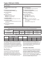
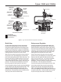
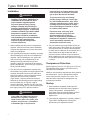
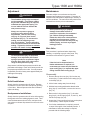
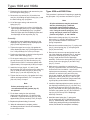
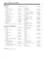
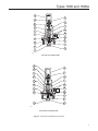
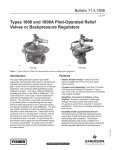
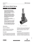
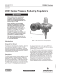
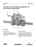
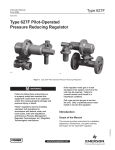
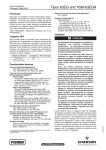
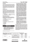
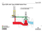
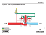
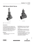
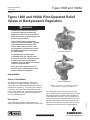
Types 1808 and 1808A
Instruction Manual
Form 5116
July 2010
Types 1808 and 1808A Pilot-Operated Relief
Valves or Backpressure Regulators
!
Warning
Failure to follow these instructions or
to properly install and maintain this
equipment could result in an explosion
and/or fire causing property damage and
personal injury or death.
Fisher® backpressure regulators or
relief valves must be installed, operated,
and maintained in accordance with
federal, state, and local codes, rules
and regulations, and Emerson Process
Management Regulator Technologies,
Inc. instructions.
W3716
Type 1808 Globe-Body
If a leak develops or if the outlet
continually vents gas, service to the
unit may be required. Failure to correct
trouble could result in a hazardous
condition. Only a qualified person must
install or service the unit.
Call a gas service person to service
the unit. Only a qualified person must
install or service the regulator.
Introduction
Scope of the Manual
W3507
Description
Types 1808 globe-body and 1808A angle-body,
pilot-operated backpressure regulators or relief valves
Type 1808A Angle-Body
Figure 1. Types 1808 and 1808A Pilot-Operated
Relief Valves or Backpressure Regulators
are economical, compact devices used in either
gas or liquid service to maintain pressure on oil and
gas separators and in pressure relief applications
in gas distribution systems. The Type 6358 pilot is
used in backpressure regulation and pressure relief
applications throughout the oil and gas production
industry, and is used in either gas or liquid service.
Pressure relief and liquid service applications in
www.fisherregulators.com
D100347X012
This manual provides installation, adjustment,
maintenance, and parts ordering information for
Types 1808 and 1808A pilot-operated relief valves or
backpressure regulators. The manual also includes
coverage of the Types 6358 and 6358B pilots and, if
used, a P590 Series filter. Instructions and parts lists
for other equipment used with these regulators are
found in separate manuals.
Types 1808 and 1808A
Specifications
Body Size and End Connection Style
2 NPT
Pressure Registration
Internal (standard) or External (optional)
Maximum Relief (Inlet) Pressure(1)
150 psig (10,3 bar) including buildup
Pilot Tubing and Connections
1/4 NPT with or without P590 Series filter
Set Pressure Ranges
See Table 1
Temperature Capabilities(2)
-20° to 180°F (-29° to 82°C)
Differential Pressures
Maximum: 125 psig (8,6 bar)
Minimum: 5 psig (0,34 bar)
Approximate Weights
Type 1808: 22 pounds (10 kg)
Type 1808A: 25 pounds (11 kg)
Type 6358 Pilot Bleed
Bleeds only when repositioning the main valve
Options
• Upstream control line construction
• Pressure gauge (0 to 160 psig/0 to 11,0 bar/
0 to 1,1 MPa)
• P590 Series Pilot Supply Filter
Type 6358B Pilot Bleed
Continuously bleeds while inlet pressure is above set pressure
Flow and Sizing Coefficients
See Table 2 1. The pressure/temperature limits in this Instruction Manual and any applicable standard or code limitation should not be exceeded.
Table 1. Types 6358 and 6358B Set Pressure Ranges, Pressure Ratings, and Pilot Spring Information
Set Pressure Ranges,
psig (bar)
3 to 18 (0,21 to 1,2)
15 to 40 (1,0 to 2,8)
35 to 125 (2,4 to 8,6)
PILOT SPRING Information
Part Number
Color
Wire Diameter,
Inches (mm)
1B986027212
1e392527022
1k748527202
Green
Yellow
Red
0.120 (3,05)
0.148 (3,76)
0.192 (4,88)
Free Length,
Inches (mm)
2.12 (54,0)
2.00 (51,0)
2.19 (55,6)
Table 2. Types 1808 and 1808A Flow Coefficients
type
flow coefficients
(wide-open)
Km
C1
iec sizing coefficients
Cg
Cv
XT
FD
FL
1808
1410
40.1
0.79
35.2
0.78
0.50
0.89
1808A
1800
51.4
0.76
35.0
0.78
0.50
0.87
the oil and gas industry are typically handled by the
Type 6358B pilot. With either pilot, the set pressure
is varied to individual requirements by the adjusting
screw on the pilot. Pilot exhaust can be piped into the
downstream line or vented into the atmosphere on gas
service and should be piped downstream or to a safe
location on liquid service.
diameter is indicated by a letter stamped on the
bottom of the pilot body next to the tapped side outlet:
an H for the yellow high-gain restriction and an L for
the blue low-gain restriction. The pilot spring range
appears on the pilot spring case.
Specifications
A pressure relief valve is a control device that opens
to relieve fluid to atmosphere during an overpressure
occurrence. A backpressure regulator is a control
device that maintains a constant upstream pressure
throughout a given flow range. It functions in the same
manner as a relief valve that opens on increasing
upstream pressure. The Type 1808 or 1808A cannot
be used as an ASME safety relief valves.
The Specifications section provides ratings and
specifications for Types 1808 and 1808A relief
valves or backpressure regulators. Some of the
specifications for a given unit as it comes from the
factory appear on the nameplate attached to the upper
diaphragm case. The Type 6358B pilot restriction
2
Principle of Operation
Types 1808 and 1808A
upper portion
of valve plug
diaphragm
assembly
to exhaust
port
pilot exhaust
hollow
passage
in valve
plug stem
lower portion
of valve plug
pilot
to main valve
diaphragm
restriction plug
TYPE 6358 BACKPRESSURE SERVICE
spring
diaphragm
upper portion
of valve plug
diaphragm
assembly
to exhaust
port
hollow
passage
in valve
plug stem
lower portion
of valve plug
to main valve
diaphragm
FIXED RESTRICTION
valve plug
TYPE 6358B RELIEF SERVICE
main valve
INLET PRESSURE
atmospheric pressure
Outlet/exhaust Pressure
loading pressure
E0075
Figure 2. Type 1808 with 6358 Series Operational Schematics
Relief Valve
Backpressure Regulator
As long as the inlet pressure is below set pressure,
the pilot control spring keeps the valve plug closed.
Inlet pressure passes through the pilot restriction and
registers as loading pressure on top of the diaphragm.
Force from the main spring, in addition to inlet pressure
bleeding through the pilot restriction, provide downward
loading pressure to keep the main valve closed.
As long as inlet pressure remains below setpoint, the
pilot spring keeps the valve plug closed. Inlet pressure
passes through the upper port around the upper portion
of the valve plug then through the hollow passage in that
valve plug. Force from the main spring, along with inlet
pressure bleeding through the pilot, provide downward
loading pressure to keep the main valve closed.
When the inlet pressure rises above the set pressure,
the pressure on the pilot diaphragm overcomes the
pilot control spring and opens the pilot valve plug. The
pilot then exhausts the loading pressure from the top
of the main valve diaphragm. The pilot continuously
exhausts gas when the inlet pressure is above the set
pressure. The inlet pressure unbalance overcomes
the main spring force and opens the main valve.
When inlet pressure rises above the set pressure,
pressure on the pilot diaphragm overcomes the control
spring to close the upper port and stroke the valve
plug to open the lower port. The pilot then exhausts
loading pressure from the top of the main valve
diaphragm. The pilot exhausts only while repositioning
the main valve. The inlet pressure unbalance
overcomes the spring force and opens the main valve.
As the inlet pressure drops, the pilot control spring begins
to close the pilot valve plug and the exhaust slows. This
causes the inlet pressure to build in the main valve
diaphragm casing, allowing the control spring to close
the main valve. Once the main valve is closed, the pilot
valve plug closes and the exhaust stops.
As the inlet pressure drops, the pilot control spring
begins to close the pilot valve plug and the exhaust
slows. This causes the inlet pressure to build in the
main valve diaphragm casing, allowing the control spring
to close the main valve. Once the main valve is closed,
the pilot valve plug closes and the exhaust stops.
3
Types 1808 and 1808A
Installation
!
Warning
Installing a Type 1808 or 1808A where its
capabilities can be exceeded or where
proper operation might be impaired
may cause personal injury, property
damage, or leakage due to bursting of
pressure-containing parts or explosion of
accumulated gas or liquid. To avoid such
conditions, install the Type 1808 or 1808A
backpressure regulator or relief valve
where service conditions are within the
unit capabilities given in the Specifications
section and unit is protected from
exposure to physical damage and/or
corrosive substances.
1.
When installing the relief valve or backpressure
regulator, make sure that the system installation
complies with applicable local, state, and federal
codes and regulations.
2. Use qualified personnel when installing, operating,
and maintaining the relief valve or backpressure
regulator. Before installing the unit, inspect the
main valve body, pilot, and pipelines for any
damage or foreign material that may have
collected. Apply pipe compound to the external
pipeline threads only. Do not use pipe compound
on any internal threads.
3. The relief valve or backpressure regulator may
be installed in any position as long as pipeline flow
complies with the flow arrow on the main valve
body (Type 1808) or runs in through the bottom
connection and out the side connection
(Type 1808A). Superior performance may be
obtained by disconnecting the pilot supply tubing
from the elbow (key 36, Figures 3 and 4),
removing the elbow, installing 1/4 NPT pipe plug
into the lower casing (key 2), and connecting the
pilot supply tubing to an upstream location.
!
Warning
Types 1808 and 1808A relief valves or
backpressure regulators vent gas or
liquid from the main valve outlet, pilot
exhaust, and pilot vent. In hazardous
or flammable gas or liquid service,
4
personal injury or property damage may
occur due to fire or explosion of vented
gas or liquid that has accumulated.
To prevent such injury and damage,
provide piping or tubing to vent the gas
to a well ventilated location. Also, when
venting a hazardous gas or liquid, piping
or tubing should be located far enough
from any buildings or windows so as not
to create a further hazard.
Protect the main valve body, pilot
exhaust, and pilot spring case vent
against anything that could clog
them. For safety during shutdown of
backpressure regulators, install vent
valves immediately upstream and
downstream of the main valve.
4. The pilot exhaust may be piped directly into the
main valve outlet (if the exhaust is to be retained,
as in liquid service) or vented to the atmosphere.
In either case, the diameter of the exhaust line or
stack should be as large as practical with a
minimum number of bends or other restrictions.
When installing this unit in relief service, be sure
to consider the jet thrust effect that will occur when
it relieves.
Overpressure Protection
Relief ranges are from 3 to 125 psig (0,21 to 8,6 bar).
The individual spring range of your relief valve is
stamped on the nameplate.
Maximum inlet pressures depend upon body material
and temperature. See the Specifications section
for the maximum inlet pressure of the valve. The
valve should be inspected for damage after any
overpressure condition.
Startup
1. With installation completed, slowly open the
upstream shut-off valve while using a gauge to
monitor inlet pressure. On backpressure
applications using an isolating bypass, open the
downstream shut-off valve, and close the
bypass valve.
2. If set pressure adjustment is necessary, adjust a
Type 6358 or 6358B pilot by following the
procedures in the adjustment section.
Types 1808 and 1808A
Adjustment
Maintenance
!
Warning
The allowable spring range is stamped
on the nameplate. If a pressure setting
beyond the indicated range is required,
substitute the appropriate spring. Be
sure to label the valve to indicate the
new pressure range.
Always use a pressure gauge to
monitor pressure when making
adjustments. Remove the closing
cap (key 12, Figure 6) then loosen
the locknut (key 11). To increase the
setting, turn the adjusting screw
(key 10) clockwise. Turn the adjusting
screw counterclockwise to decrease the
setting. Tighten the locknut to maintain
position and install closing cap.
!
Warning
To avoid personal injury or equipment
damage, never adjust the pilot control
spring to produce a set pressure higher
than the upper limit of the set pressure
range for that particular spring.
Set pressure is defined as the pressure at which the
pilot starts to discharge. Each unit is factory-set for the
set pressure specified on the order. If no set pressure
is specified, the unit is factory-set at approximately the
midrange of the spring.
Shutdown
Relief Installations
Parts are subject to normal wear and must be
inspected and replaced as necessary. Frequency of
inspection and maintenance depend upon severity of
service conditions. The main valve body need not be
removed from the line prior to maintenance.
!
Warning
Avoid personal injury or property
damage from sudden release of
pressure or explosion of accumulated
gas. Before starting disassembly,
isolate the relief valve or backpressure
regulator from line pressure, release
trapped pressure from the body and any
isolated piping, and vent any trapped
loading pressure.
Main Valve
This procedure is performed when inspecting,
cleaning, or replacing any main valve parts. Key
numbers are referenced in Figures 3 and 4.
Note
If the trim is to be inspected and no
further maintenance is required, it is
unnecessary to remove the pilot from the
upper casing (key 1) or separate the upper
casing from the lower casing (key 2).
Disassembly
1. Remove the two hex nuts (key 18) from the cap
screws (key 17) that hold the lower casing (key 2)
to the body (key 8).
Slowly close the upstream shut-off valves. Release
all pressure from the main valve and pilot by opening
a vent valve. When all pressure has been released,
tighten the fitting.
2. Lift the lower casing away from the body.
Backpressure Installations
4. Remove the O-ring retainer (key 7), the valve
plug (key 6), the O-rings (keys 9, 10, and 11), and
the back-up rings (key 19).
Slowly close the upstream shut-off valve while opening
the bypass valve if an isolating bypass is used. Then
close the downstream shut-off valve, and open both
vent valves to release all pressure from the main valve
and pilot.
3. With the lower casing positioned so that the valve
plug (key 6) is accessible, remove the hex nut
(key 14).
5. Inspect the O-rings and back-up rings, and replace
as necessary. Check all parts for wear.
6. If no further maintenance is required, proceed
to steps 5 through 8 of the Assembly section. If
maintenance inside the casings is required,
proceed with the following steps.
5
Types 1808 and 1808A
7. Disconnect the pilot tubing, and unscrew the pilot
from the upper casing (key 1).
8. Remove the cap screws (key 15) and the hex
nuts (key 16) holding the upper casing (key 1) and
the lower casing (key 2) together.
Types 6358 and 6358B Pilots
This procedure is performed if inspecting or replacing
any pilot parts. Key numbers are shown in Figure 6.
Note
9. Lift off the upper casing, and remove the
spring (key 12).
All pilot maintenance may be performed
with the pilot body (key 1) attached
to the pipe nipple unless the body is
removed or the entire pilot replaced as a
unit. If only the control spring (key 7) or
spring seat (key 8) needs to be replaced,
perform only steps 1, 2, and 6 below.
10. Remove the upper hex nut (key 14) holding the
upper diaphragm plate (key 4), lower diaphragm
plate (key 5), and diaphragm (key 3) together.
Slide the upper and lower diaphragm plates and
the diaphragm off the cap screw (key 13).
Assembly
1. Assemble the upper diaphragm plate (key 4), the
diaphragm (key 3), and the lower diaphragm plate
(key 5) on the cap screw (key 13).
2. Tighten the upper hex nut (key 14) against the
lower diaphragm plate (key 5) with approximately
5 to 7 foot-pounds (6,8 to 9,5 N•m) of torque.
3. Position the diaphragm so that its holes align with
those in the lower casing (key 2).
4. Fit the upper casing (key 1) in place, and install
the cap screws (key 15) and hex nuts (key 16).
Tighten the hex nuts in a crisscross pattern with
approximately 15 foot-pounds (20 N•m) of torque.
5. Install the O-rings (keys 9, 10, and 11) and
back-up rings (key 19) into place on the valve plug
(key 6). Slide the valve plug (key 6) and O-ring
retainer (key 7) over the cap screw (key 13).
6. Tighten the hex nuts (key 14) against the O-ring
retainer with approximately 5 to 7 foot-pounds
(6,8 to 9,5 N•m) of torque.
Note
Before performing step 7, it is
recommended that the gaskets (key 21)
be replaced.
7. Fit the lower casing into the valve body,
aligning the cap screws (key 17) with the holes
in the body. Tighten the hex nuts (key 18) using
approximately 20 foot-pounds (27 N•m) of torque.
8. Replace the pilot and tubing, if removed.
9. When all maintenance is complete, perform
the Startup procedure if the unit will immediately
be returned to service.
6
1.
Remove the closing cap (key 12), loosen the
locknut (key 11), and turn the adjusting screw
(key 10) counterclockwise to remove the
spring compression.
2. Remove the machine screws (key 17), spring case
(key 2), control spring (key 7), and spring seat
(key 8) from the body.
3. Remove the connector cap and gasket from the
top of the diaphragm assembly (key 5), and then
remove the valve spring (key 14). Unclip the
E-ring (if used) and remove the diaphragm
assembly. Remove the stem guide (key 9) to gain
access to the valve plug (key 4) and the O-ring
(key 37), if used.
4. Make sure the restriction or restriction plug
(key 20), registration hole, and valve plug seating
surfaces are free from debris. Inspect and
replace parts as necessary, making sure that the
restriction or restriction plug and valve plug
(key 4) are installed, and then secure the valve
plug with the stem guide (key 9). With a Type
6358 pilot, coat the restriction plug threads with
a good quality sealant before installation.
5. Install the diaphragm/plate/connector portion of
the diaphragm assembly (key 5), clip the E-ring (if used) to the grooved end of the valve plug
(key 4), and install the valve plug spring (key 14),
connector cap gasket (key 36), and connector
cap (key 6) into the top of the diaphragm
assembly connector.
6. Install the control spring (key 7), spring seat
(key 8), spring case (key 2), and machine screws
(key 17). After assembly, make sure of the proper
control spring setting according to the Adjustment
section, and remark the nameplate if necessary.
Types 1808 and 1808A
P590 Series Filter
Key Description This procedure is to be performed if it is necessary to
clean or replace filter parts in a Type P593-1 or P594-1
filter assembly.
1.
Remove the following as shown in Figure 5: filter
body (key 1), machine screw (key 4), spring washer
(key 6), gasket (key 7), two flat washers (key 5),
and filter element (key 2).
2. Upon reassembly, one of the flat washers must
go between the filter element and filter head
(key 3), and the other must go between the filter
element and gasket.
3. Use pipe thread sealant on the filter head
pipe threads.
12
Spring, Zinc-plated steel
15A8775X012
13
Cap Screw, Zinc-plated steel
15A7839X012
Hex Nut, Steel (2 required)
1V136228982
15
Cap Screw, Zinc-plated steel (12 required)
1E760324052
16
Hex Nut, Zinc-plated steel (12 required)
1A346524122
17
Cap Screw, Zinc-plated steel (2 required)
14
Type 1808
15A7835X012
Type 1808A
17A9766X012
18
When corresponding with your local Sales Office about
this equipment, always reference the equipment
serial number or FS number that can be found on
the nameplate.
Hex Nut, Zinc-plated steel (2 required)
1E944524112
19* Back-up Ring,
Polytetrafluoroethylene (PTFE) (2 required)
20
1U529406992
Valve Plug Guide, Stainless steel
15A7832X012
21* Gasket, Nitrile (NBR) (2 required)
15A7836X012
36
Parts Ordering
Part Number
Elbow
Copper Tube
-----------
Steel Tube
----------
-----------
36 Pipe Plug, Steel (with upstream registration)
Stainless steel
-----------
Pilot Mounting Parts
When ordering replacement parts, reference the
11-character key number of each needed part as found
in the following parts list. Separate kits containing all
recommended spare parts are available.
Key Description 21
Part Number
Filter
Standard, Brass Type P594-1
Corrosive, Aluminum
Type P593-1
Parts List
Corrosive (NACE), Brass
Type P593-1
Main Valve Types 1808 and 1808A
Galvanized steel (standard)
-----------
Zinc-plated steel (NACE)
-----------
Key Description Part Number
Parts Kit (includes keys 3, 9, 10, 11, 19, and 21)
R1808X00012
1
Upper Casing, Steel
25A7831X012
2
Lower Casing, Steel
25A7828X012
3*
Diaphragm Assembly, Nitrile (NBR)
10A0288X012
4
Upper Diaphragm Plate, Zinc-plated steel
15A7834X012
5
Lower Diaphragm Plate, Zinc-plated steel
14A9681X012
6*
Valve Plug, Stainless steel
15A7826X012
7
O-Ring Retainer, Steel
15A7827X012
8
Body
Type 1808
Cast iron
25A7830X012
WCC Steel, NACE
25A7926X022
Type 1808A, Cast iron
37A7694X012
9* O-Ring, Nitrile (NBR)
15A8508X012
10* O-Ring, Nitrile (NBR)
1C628006992
11* O-Ring, Nitrile (NBR)
1F358106992
22
24
Pipe Nipple
Pipe Tee
Malleable iron (standard)
-----------
316 Stainless steel (NACE)
-----------
25
Connector Fitting, Without upstream registration
Without Filter
Steel (standard)
-----------
316 Stainless steel (NACE)
-----------
26
Elbow Fitting, Without upstream registration
With Filter
Standard -----------
316 Stainless steel (NACE)
-----------
27
Vent Assembly
Type Y602-11
28
Tubing,
316 Stainless steel (without upstream registration)
-----------
29* Gauge, 0 to 160 psig/0 to 11,0 bar/0 to 1,1 MPa
11B8579X042
29
Pipe Plug
Zinc-plated steel (NACE)
-----------
316 Stainless steel (NACE)
-----------
*Recommended spare part
7
Types 1808 and 1808A
12
13
1
4
15
19
16
10
2
36
3
21
5
17
11
18
20
9
6
14
7
8
47A7696-A
13
4
19
10
36
21
17
18
9
14
8
8
47A7696-A
Figure 3. Type 1808A Assembly
A
Types 1808 and 1808A
1
c
D
12
13
3
4
15
19
16
36
2
10
21
17
5
18
11
9
20
14
6
45A7841-D
8
7
Figure 4. Type 1808 Assembly
6
A7008
7
5
1
2
4
5
3
Figure 5. P590 Series Filter Assembly
9
Types 1808 and 1808A
P590 Series
Key Description 1
Part Number
Filter Body
Key Description 6
Part Number
Connector Cap
Type P594-1, Brass
1E312414012
18-8 Stainless steel
16A2921X012
Type P593-1 (NACE), Aluminum
1E3124X0022
316 Stainless steel
16A2921X022
2*
Filter Element, Cellulose
1E312606992
7
3
Filter Head Spring
3 to 18 psig (0,21 to 1,2 bar), Green
1B986027212
Type P594-1, Brass
1E312514012
15 to 40 psig (1,0 to 2,8 bar), Yellow
1E392527022
Type P593-1 (NACE), Aluminum
1E3125X0022
35 to 125 psig (2,4 to 8,6 bar), Red
1K748527202
8
Spring Seat, Steel
1B798525062
Stem Guide
4
Machine Screw
Type P594-1, Brass
1J500218992
9
Type P593-1 (NACE), Aluminum
1J500209012
416 Stainless steel (standard)
16A2923X012
174 Stainless steel
16A2923X022
1J500018992
10
Adjusting Screw, Zinc-plated steel
10B7192X012
1J500010062
11
Locknut, Steel
1A946324122
12
Closing Cap
5
Washer, 2 required
Type P594-1, Brass
Type P593-1, Aluminum
6*
Spring Washer, Steel
1H885128982
7*
Gasket, Composition
1F826804022
12
Seal Wire,
304 Stainless Steel (for Type P593-1, NACE only)
1U7581X0022
Types 6358 and 6358B Pilots
Key Description 1
Part Number
Body
CF8M Stainless steel
39A5972X012
Aluminum
39A0138X012
2
Spring Case
316 Stainless steel
28A9277X012
Aluminum
25A6220X012
3
Body Plug
316 Stainless steel
1B797535072
Aluminum
1B797509032
4*
Valve Plug
303 Stainless steel/Nitrile (NBR) (standard)
14B6372X012
UHMWPE
16A2924X012
5*
Diaphragm Assembly
Steel / Nitrile (NBR) (standard)
15A6216X072
Steel / Neoprene (CR)
15A6216X212
Steel / Fluorocarbon (FKM)
15A6216X172
Steel / Nitrile (NBR) (for Type 6358B only)
2 to 10 psig (0,14 to 0,69 bar)
*Recommended spare part.
Inconel® is a marked owned by Special Metals Corporation
10
15A6216X182
Plastic
23B9152X012
303 Stainless steel
1H2369X0032
13* Body Plug Gasket, Composition
1C495704022
14
Valve Spring
302 Stainless steel (standard)
1E701337022
Inconel®
19A8179X012
16
Vent Assembly (2 required)
Type Y602-12
17
Machine Screw, (6 required)
Stainless steel
10B6189X022
Steel
1V4360X0022
20
Restriction
Type 6358
Steel
1A346128982
Stainless steel
1V7435X0012
Type 6358B
High-Gain, Yellow
Steel
17A7279X012
17A7279X032
Stainless steel
20* Restriction
Type 6358B
Medium-Gain, Steel, Red
Low-Gain, Steel, Blue 36* Gasket, Fluorocarbon (FKM), (2 required)
17A2029X012
17A7277X012 1U1716X0012
37* O-ring
Nitrile (NBR)
16A2920X012
Fluorocarbon (FKM)
16A2920X022
Types 1808 and 1808A
12
11
10
2
19
7
8
6
36
5
16
20
14
4
9
1
37
13
3
A6920
Type 6358 Pilot Interior view
10
12
19
8
11
6
2
5
7
14
36
9
16
37
20
4
1
3
13
B2619-2
Type 6358B Pilot Interior view
Figure 6. Types 6358 and 6358B Pilot Assemblies
11
Types 1808 and 1808A
Industrial Regulators
Natural Gas Technologies
TESCOM
Emerson Process Management
Regulator Technologies, Inc.
Emerson Process Management
Regulator Technologies, Inc.
Emerson Process Management
Tescom Corporation
USA - Headquarters
McKinney, Texas 75069-1872 USA
Tel: 1-800-558-5853
Outside U.S. 1-972-548-3574
USA - Headquarters
McKinney, Texas 75069-1872 USA
Tel: 1-800-558-5853
Outside U.S. 1-972-548-3574
USA - Headquarters
Elk River, Minnesota 55330-2445 USA
Tel: 1-763-241-3238
Asia-Pacific
Shanghai, China 201206
Tel: +86 21 2892 9000
Asia-Pacific
Singapore, Singapore 128461
Tel: +65 6777 8211
Europe
Bologna, Italy 40013
Tel: +39 051 4190611
Europe
Bologna, Italy 40013
Tel: +39 051 4190611
Gallardon, France 28320
Tel: +33 (0)2 37 33 47 00
Middle East and Africa
Dubai, United Arab Emirates
Tel: +971 4811 8100
Europe
Selmsdorf, Germany 23923
Tel: +49 (0) 38823 31 0
For further information visit www.fisherregulators.com
The Emerson logo is a trademark and service mark of Emerson Electric Co. All other marks are the property of their prospective owners. Fisher is a mark owned by Fisher Controls, Inc., a
business of Emerson Process Management.
The contents of this publication are presented for informational purposes only, and while every effort has been made to ensure their accuracy, they are not to be construed as warranties or
guarantees, express or implied, regarding the products or services described herein or their use or applicability. We reserve the right to modify or improve the designs or specifications of such
products at any time without notice.
Emerson Process Management does not assume responsibility for the selection, use or maintenance of any product. Responsibility for proper selection, use and maintenance of any Emerson
Process Management product remains solely with the purchaser.
©Emerson Process Management Regulator Technologies, Inc., 1978, 2010; All Rights Reserved