1
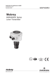
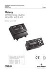
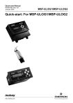
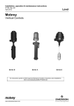
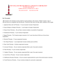
Installation, Operation & Maintenance Manual
IP2040/IM, Rev. AA
May 2007
Mobrey
MSP900SH Series Level Transmitter
Software version 2.1
www.mobrey.com
Page 1
MSP900SH
Installation, Operation & Maintenance Manual
IP2040/IM, Rev. AA
May 2007
MSP900SH
CONTENTS
Page
1.
Introduction
3
2.
2.1
2.2
2.3
2.4
The MSP900SH ultrasonic level transmitter
Type numbering system
Safety data
Pressure Equipment Directive
Specifications
3
3
4
4
4
3.
3.1
3.1.1
3.1.2
3.1.3
3.1.4
3.2
3.3
3.4
3.4.1
3.4.2
3.5
3.6
3.6.1
Installation
Location of the MSP900SH transmitter
General considerations
Liquid surface conditions
In-tank / well effects
Open Channel Flow installations
Mounting the transmitter above the liquid surface
Wiring
Additional components in the 2 wire loop
Safety Barriers
Lightning / surge protection and other loop devices
Wiring to allow HART communication
Use with Mobrey Measurement MSP90 Series controllers
Wiring
5
5
6
6
6
6
8
8
9
9
9
9
9
10
4.
Maintenance
10
5.
5.1
5.2
Commissioning / Programming
Current output
Hart programming of the MSP900SH transmitter
11
11
11
6.
6.1
6.2
Accessories
Submersion sheild
Head Verification Device
12
12
12
Appendices
Appendix 1 MSP900SH Programming parameters
Appendix 2 Use with Mobrey Measurement MSP90 Series controllers - Example
Appendix 3 71097/1131 FM Intrinsically Safe Control (Entity) Drawing
13
14
15
Footnote :In this manual the following terms are used which refer to trademarks from other manufacturers:
HART: is the protocol adopted for the MSP900 SMART Communications.
HART is a registered trademark of the HART Communications Foundation and is a mnemonic for
Highway Addressable Remote Transducer.
Page 2
Installation, Operation & Maintenance Manual
IP2040/IM, Rev. AA
May 2007
1.0
MSP900SH
Introduction
The MSP900 ultrasonic level transmitter is designed to be mounted above a liquid and will measure the distance to the liquid
surface.
When programmed with details of the vessel, sump or open channel, the MSP900 will compute level, contents or flow and give
a 4-20mA signal proportional to the chosen variable. Full programming details are given in the Operating Manual IP2040/OM.
MSP900 is a two wire 24V dc loop powered transmitter and may be connected to any suitable dc power source using the
factory fitted cable. The Mobrey Measurement MCU900 range of Control Units is designed to be used with the MSP900
Transmitter in this way.
The MSP900 transmitter may be mounted in a hazardous area provided that it is supplied from a protected power supply.
When using the MSP900 transmitter with an MCU900 Control Unit, no external Intrinsically Safe Barriers are required as all
protection is built-in to the MCU900 Control Unit.
When using any other power supply, it is the responsibility of the user to ensure suitable Intrinsically Safe Barriers are
installed. Full details are given in section 3.4.1
2.0
The MSP900SH ultrasonic level transmitter.
The transmitter is a factory sealed unit with an operating range of 0.3m to 12m. When powered up the transmitter will give a
4-20mA signal on the two wire power cable over the factory default range : 4mA at 12m; 20mA at 0.3m. This range may be
adjusted using a HART programmer. See section 5.0
(Note: full programming instructions are given in the Operating Manual IP2040/OM)
Fig (i)
A Stainless Steel mounting bracket and 1” thread type – G1” (1” BSPP) (-A); 1” NPT (-U) Nylon locknut are supplied with the
transmitter to facilitate mounting.
2.1
Type numbering system
MSP Mobrey Ultrasonic level transmitter
900
UPVC construction, 12m operating range
SH
Factory sealed transmitter, HART communications
-A
-U
ATEX & CSA certified intrinsically safe for Zone 0
FM & CSA certified intrinsically safe for Zone 0 and FM for DIV 1
/3
/20
/50
Page 3
Fitted with 3m two core shielded cable
Fitted with 20m two core shielded cable
Fitted with 50m two core shielded cable
Installation, Operation & Maintenance Manual
IP2040/IM, Rev. AA
May 2007
MSP900SH
2.2
Safety Data
Type numbers
Certificate numbers
ATEX
CSA
ATEX Coding
(EU Directive 94/9/EC)
MSP900SH-A/**
BAS01ATEX1061X
1352094X
FM
CSA
MSP900SH-U/**
3021193
1352094X
II I G
Cenelec Coding
EEx ia IIC T4 (-40°C<Ta<60°C)
EEx ia IIC T6 (-40°C<Ta<55°C)
CSA Coding
Ex ia IIC T4 (-40°C<Ta<60°C)
Ex ia IIC T6 (-40°C<Ta<55°C)
FM Coding
Ex ia IIC T4 (-40°C<Ta<60°C)
Ex ia IIC T6 (-40°C<Ta<55°C)
IS/I/1/ABCD T6 Ta = 55°C
T4 Ta = 60°C
IS/I/0/AEx ia IIC T6 Ta = 55°C
T4 Ta = 60°C
Safety parameters
Ui
Ii
Pi
Li
Ci
2.3
30 V
120mA
0.82W
27mH
5nF
Ui (Vmax)
Ii (lmax)
Pi
Li
Ci
30 V
120mA
0.82W
27mH
5nF
Pressure Equipment Directive
The MSP900SH transmitter does not enclose a pressurised volume and therefore is a component and outside the scope of the
Pressure Equipment Directive 97/ 23/EC.
Accordingly, the Declaration of Conformity for the MSP900SH does not list the Pressure Equipment Directive.
2.4
Specifications
Materials of construction:
Body Material
Cable sealant
Locknut
Bracket
Cable
Electrical
Supply voltage
Output
Communications
Earthing
Cable size
Cable length
Cable resistance
UPVC (stabilised)
Epoxy adhesive
Nylon
316 Stainless Steel
PVC sheathed two core shielded cable
Transmitter in Non Hazardous area:
12-40V dc
Transmitter in Hazardous area:
12-30V dc
4-20mA
HART Digital communications (Rev. 5)
None required
2
Overall diameter 4mm, two cores each 0.22 mm
3m, 20m or 50m.
0.1 Ohm per metre length.
Operating
Range
Temperature
Ambient
Wetside
Pressure
0.3 to 12m
-40°C to +60°C
-40°C to +60°C
0 bar to 3.0 bar
(restricted to 0 - 1.0 bar for use in Canada)
Page 4
Installation, Operation & Maintenance Manual
IP2040/IM, Rev. AA
May 2007
3.0
MSP900SH
Installation
The MSP900SH may be mounted in a hazardous area provided it is supplied through or from a suitably protected
power supply (such as the Mobrey Measurement MCU900 Series).
Refer to the safety parameters given in section 2.2 and safety instruction leaflet IP2040/SI (-A), 71097/1131 (-U).
3.1
Location of the MSP900SH transmitter
The transmitter must be installed in a location where it is protected from ultraviolet radiation, in
order to prevent long term degradation of the plastics used in its construction e.g. shrouded from
direct sunlight.
Correct location of the transmitter is essential for the reliable operation of any ultrasonic level
measurement system. Whilst the transmitter may be site tuned to deal with most application
conditions, it is strongly recommended that the following guidelines should be adopted wherever
relevant.
For maximum accuracy and stability of the level measurement reading the transmitter should
always be shrouded from direct sunlight and any radiated heat.
The transmitter should be mounted as near vertical as possible to ensure
a good echo from the liquid surface and maximum echo size received.
The beam angle (to the half power point) of the transmitter is 12 degrees
inclusive.
If the transmitter is located near the side of the tank or well, there will be
no false echo generated provided the wall is smooth and free of
protrusions.
However, there will still be a reduction in the echo size. To avoid large
echo size loss, it is recommended that the transmitter never be mounted
closer than 300mm to the wall.
Fatty, dirty or viscous liquids can cause a “scum line” to build-up on the tank or well wall. Avoid false echoes from this by
enabling “scum line prevention” software in the MCU control unit.
If the transmitter is mounted in an enclosed tank, avoid mounting the transmitter in the centre of the tank roof as this could act
as a parabolic reflector and create unwanted echoes.
If the transmitter is mounted in a stand-off or nozzle, it is always preferable
that the transmitter face be at least 5mm proud of the stand-off such that it
protrudes beyond the stand-off and into the tank.
Remember that the minimum operating range of the transmitter is 300mm.
The transmitter will not detect any liquid surface closer than 300mm to the
transmitter face.
Obstructions in the tank or well may generate echoes which can be
confused with the real liquid surface echo. Obstructions within the beam
angle generate strong “false-echoes”; wherever possible, the transmitter
should be positioned such that false echoes are avoided.
To avoid detecting unwanted objects in the tank or well, it is advisable to
maintain a distance of at least 0.11m from the centre line of the
transmitter for every metre range to the obstruction.
Page 5
Installation, Operation & Maintenance Manual
MSP900SH
IP2040/IM, Rev. AA
May 2007
3.1.1 General considerations
•
The MSP900SH transmitter complies with the European Directive for Electro Magnetic Compatibility (EMC) Class B.
It is not advisable to mount the transmitter in close proximity to a source of electrical noise such as a variable speed
drive or other high powered electrical device.
3.1.2 Liquid surface conditions
•
Foaming liquids can reduce the size of the returned echo as foam is a poor ultrasonic reflector. It is always preferable
to mount an ultrasonic transmitter over an area of clear liquid, such as near the inlet to a tank or well. In extreme
conditions, or where this is not possible, the transmitter may be mounted in a vented stilling tube provided that the
inside bore of the stilling tube is at least 100 mm and is smooth and free from joints or protrusions. It is also preferable
that the bottom of the stilling tube does not become uncovered, thus preventing the ingress of foams.
•
Beware of mounting the transmitter directly over any inlet stream.
•
Liquid surface turbulence is not normally a problem unless it is excessive. In most cases, the effects of turbulence are
minor, with excessive turbulence being catered for by fine tuning the transmitter on site if necessary.
3.1.3 In-tank / well effects
•
Stirrers or agitators can cause a vortex. Always try to mount the transmitter off-centre of any vortex to maximise the
return echo.
As stirrer blades become uncovered they will create echoes as they pass through the ultrasonic beam. The transmitter
can be tuned to ignore these false echoes on site.
•
In non-linear tanks with rounded or conical bottoms, always mount the transmitter off-centre. In some cases, it may be
desirable to install a perforated reflector plate on the tank bottom directly under the transmitter
centre line to ensure a satisfactory return echo.
•
Avoid mounting the transmitter directly above any pumps in the well as the transmitter will detect the pump
casing as the liquid falls away. If this is not possible, fine tuning on site may be required to ignore echoes
from the pump casings.
•
If the well is subject to flooding, it is advisable to fit the transmitter with a submersion shield. Whilst the
transmitter will of course stop working whilst covered with liquid, the transmit face will be protected from
contamination by an air lock inside the shield.
3.1.4 Open Channel Flow installations
There are normally two distinct parts to an open channel flow measurement system; the primary element (flow structure) and
the secondary element (Head measurement instrumentation).
For accurate open channel flow measurement, both parts of the system must be installed accurately.
This manual explains some key aspects of the installation of the secondary element, in this case the ultrasonic transducer.
For full details of the installation of a primary element such as a flume or weir, reference should be made to the relevant British
(BS3680) or International standard.
In the United Kingdom, Mobrey Measurement offers a complete installation and commissioning service for open channel flow
measurement systems. For further information contact the sales office and/or refer to Mobrey Measurement’s ‘The Guide’.
* Positioning of the transmitter is critical and should be the correct distance upstream from the flow structure as stated in
BS3680 e.g. a distance of 4 to 5 times hmax for a thin plate weir or 3 to 4 times hmax for a flume.
For optimum accuracy. the front face of the sensor should be positioned at a height that is at least equal to the maximum flow
depth plus the blanking distance of the transducer. A minimum distance of 310mm is recommended.
Page 6
Installation, Operation & Maintenance Manual
IP2040/IM, Rev. AA
May 2007
MSP900SH
Hmax
Hmax
It is important to note that the bottom reference of the transmitter should be related to the centre of the invert of the primary
device, NOT the distance to the channel bottom directly below the transmitter.
Transmitter
bottom
Flow
Channel
invert
Primary element (eg.
Flume, weir) invert
In addition to the above, when setting the bottom reference on a ‘V’ notch weir it is important that the true invert of the weir is
taken and not the meniscus liquid level, which may be 3 to 4mm above the true invert.
Transmitter
bottom reference
True invert
Meniscus
•
The liquid surface at the point of measurement must have a stable, smooth surface and uniform approach velocity. It
must not be affected by baffles, foam, hydraulic jumps or any other object likely to cause flow disruption.
•
The primary element should be free from any situation where it is likely to ‘drown’ (refer to relevant standard for further
information)
•
The MSP900SH transmitter has integral temperature compensation and must be protected at all times from direct
sunlight and any radiated heat.
For maximum accuracy and stability of level measurement reading the transmitter should always be shrouded to
prevent the incidence of direct sunlight.
If the flow structure permits, mount the transmitter within the flow channel or chamber.
Page 7
Installation, Operation & Maintenance Manual
MSP900SH
•
IP2040/IM, Rev. AA
May 2007
In many installations, the use of a calibration device is mandatory. Mobrey Measurement offer the MSP-HVD for this
purpose, details on request.
In order to minimise measurement uncertainties when a calibration device is installed, it is recommended that the
calibrated range should be kept to a realistic minimum. i.e. max flow plus 10mm. Ensure that the target plate of the
calibration device does not fall within the 300mm blanking distance of the transmitter.
All calibrations should be derived to suit as installed conditions.
If you are in doubt about any aspect of transmitter installation, contact Mobrey Measurement (Service Division)
who will be pleased to advise.
3.2
Mounting the transmitter above the liquid surface
The transmitter is supplied with a purpose made 316 Stainless Steel mounting bracket which should be used to mount the
transmitter over the liquid surface.
The bracket is designed to fit over the 1” threaded neck of the transmitter and is retained by a locknut.
IMPORTANT : Never suspend the transmitter by the cable.
Use a chain or wire through the hole provided in the bracket, which is shaped to ensure that the transmitter will hang
perpendicular to the liquid surface.
Check that the material of the chain or wire is corrosion resistant to the liquids and any vapours present.
Alternatively, the bracket may be bolted to a suitable cross member above the liquid surface. Ensure that the transmitter is
perpendicular to the liquid surface to maximise the return echo size.
Check that the maximum liquid level will not encroach into the 0.3m blanking zone of the transmitter.
Note: To aid alignment, the echo size / signal strength can be displayed on the MCU900 control unit or on a suitable HART
compliant handheld. Refer to IP2030/OM for full details.
3.3
Wiring
The transmitter is supplied with a factory fitted length of PVC sheathed two core shielded cable which should be neatly run
back to the control unit or a suitable local IP65 junction box.
The transmitter cable cores are identified as follows :Red
Black
Screen
24V dc
0V dc
Earth : must be connected to an Intrinsically Safe Earth in the non-hazardous area if the transmitter is
installed in a hazardous area.
Connect to a standard earth if the transmitter is not in a hazardous area.
The cable may be cut to length on site or may be extended using an IP65 junction box and suitable extension cable up to a
total length of 3000 m.
Where the transmitter is installed in a hazardous area, it is the responsibility of the user to ensure that the cable parameters of
the total length of cable used together with the parameters of the MSP900SH are less than the safety parameters of the safety
barrier (or MCU900 Control Unit if used instead) . See section 3.4 .
Multicore cable may be used provided that each pair within the multicore has a separate shield.
As good instrumentation practice, avoid tracking the cable with other cables which carry high voltages if possible.
Page 8
Installation, Operation & Maintenance Manual
IP2040/IM, Rev. AA
May 2007
3.4
MSP900SH
Additional components in the two wire loop
3.4.1 Safety barriers – installation of the transmitter in a hazardous area
When used with the Mobrey Measurement Control Unit Series MCU900, NO additional safety barriers are required as the
output from the control unit is Intrinsically Safe (refer to manual IP2030/IM supplied with the control unit for full details)
If powering the transmitter from any other power supply, it is the responsibility of the user to ensure a suitable Intrinsically Safe
barrier is fitted in the safe area.
The barrier must be chosen such that it’s output parameters Uo, Io and Po are less than Ui, Ii and Pi of the MSP900SH
transmitter.
For the MSP900SH transmitter, Ui = 30V, Ii = 120mA and Pi = 0.82W.
In addition, the sum of the capacitance and the inductance of the transmitter and any extra cable fitted must not exceed the
maximum specified for the barrier chosen.
For the MSP900SH transmitter with 50m of factory fitted cable, Ci = 5nF and Li = 27mH
Suitable barriers include the MTL products 706, 706S, 787, and 787S.
3.4.2
Lightning / surge protection and other loop devices
It is allowable to fit loop powered or separately powered devices in the two wire loop provided that the transmitter receives a
minimum voltage of 12V dc at 21 mA loop current.
It is the responsibility of the user to ensure any loop devices, if mounted in the hazardous area, carry the requisite hazardous
area certification and do not cause the system parameters to exceed those of the safety barrier (or MCU900).
If the area is prone to lightning strikes or voltage surges, fitting of a supressor device is desirable between the transmitter and
the control unit.
3.5
Wiring to allow HART communication
When used with the Mobrey Measurement MCU900 Control Unit, there is no need to install an external load resistor in the
loop as there is a suitable resistor built in to the Control Unit.
If it is intended to use HART digital communications with the MSP900SH transmitter, a 250Ohm 0.25W load resistor must be
installed in the loop.
If the transmitter is being supplied through a safety barrier, ensure the type chosen will pass HART/SMART information.
Once installed, a HART communicator can be connected across the load resistor, or across the loop at any point downstream
of the load resistor.
It is the responsibility of the user to ensure that any HART communicator used in the hazardous area is suitably certified for
that area.
3.6 Using the MSP900SH transmitter with an MSP90 Series controller
Although the MSP900SH transmitter is designed for use with the new MCU900 Series control units, there are many thousands
of MSP90 Series control units in the field with which it may be used.
It is important to note that the MSP90 Controller was normally used with an MSP90 style ultrasonic transducer, with the
controller supplying a voltage pulse to the transmitter and then interpreting and processing the return echo.
The MSP900 transmitter works in a different way, as it performs all processing in the transmitter itself, requiring only a loop
power connection to the control unit.
Page 9
Installation, Operation & Maintenance Manual
IP2040/IM, Rev. AA
May 2007
MSP900SH
3.6.1 Wiring
When connecting the MSP900SH transmitter to an MSP90 Series control unit, different terminals are used in the control unit.
If connected, disconnect the existing MSP90 type transducer. These terminals are not used with the new MSP900SH type
transmitters.
Connect the MSP900SH screened and twisted pair cable to the current input terminals of the MSP90 Controller as follows:
MSP900SH wire
Red
Black
Wall mount controller type
MSP90 - 11- C
Terminal 18 : I in Loop Power+
Terminal 14 : 4-20mA I in+
Panel mount controller type
MSP90 - 61* - C
Terminal 18 : I in Loop Power+
Terminal 8 : Current in+
Important note when the transmitter is located in a hazardous area:
If the MSP900SH transmitter is located in a hazardous area, it is the responsibility of the user to ensure that a suitable
Intrinsically Safe barrier is fitted in the safe area.
The barrier must be chosen such that it’s output parameters Uo, Io and Po are less than Ui, Ii and Pi of the MSP900SH
transmitter.
For the MSP900SH transmitter, Ui = 30V, Ii = 120mA and Pi = 0.82W.
In addition, the sum of the capacitance and the inductance of the transmitter and any extra cable fitted must not exceed the
maximum specified for the barrier chosen.
For the MSP900SH transmitter with 50m of factory fitted cable, Ci = 5nF and Li = 27uH
Suitable barriers include the MTL products 706, 706S, 787, and 787S.
3.6.2
Programming the MSP90 Series control unit to operate with the MSP900SH transmitter
The MSP900SH is a transmitter and will need to be programmed to give a 4-20mA signal proportional to the level in the tank.
(See Section 5 of this manual)
On the MSP90 control unit :
Set P39 to 7. This sets the MSP90 control unit to current input mode.
Set P03 to the value, in metres, corresponding to the range of the 4-20mA output of the MSP900SH transmitter.
In a tank or sump of depth 8.5m, you will most likely have programmed the MSP900SH to give 4-20mA over the range 0.3m to
8.5m. P03 in the MSP90 control unit will therefore need to be set to 8.2.
P21 is a parameter which is used to convert level measurement to contents measurement. Where the vessel is a simple tank
or sump and the readout is required to be level, leave P21 set to 0.
If it is required to give a readout in contents, P21 should be set dependant upon vessel shape - refer to the MSP90 controller
manual.
A typical example is given in Appendix 2 of this manual.
Refer to the manual supplied with the MSP90 Control unit for full programming details of the MSP90 control unit if in any
doubt.
4.0.
Maintenance
There is no routine maintenance required for the MSP900SH other than an occasional check to ensure that the front face of
the transmitter is clean and that the wiring is in good condition.
Page 10
Installation, Operation & Maintenance Manual
IP2040/IM, Rev. AA
May 2007
MSP900SH
5.0
Commissioning / Programming
5.1.
Current Output
This section gives a very brief overview to allow checking of the installation. For full programming details, refer to the
Operating Manual IP2040/OM.
When power is applied to the transmitter it will give a 4-20mA signal proportional to “level” based on some factory set default
values for a typical tank :Bottom reference (depth of tank)
4mA level
20mA level
12m from transducer face
0m
11.7m
Hence, for a liquid surface (or other flat target) that is 5m away, the current on the loop will represent a liquid level of
(12m – 5m) = 7m with a value of 13.57mA.
The user may programme the MSP900SH transmitter with the specific installation details to re-range the 4-20mA signal.
The MSP900SH transmitter is usually connected to a Mobrey Measurement MCU900 control unit which allows access to and
changing of the transmitter operating parameters.
5.2.
HART programming of the MSP900SH transmitter
If being used without the MCU900 Control Unit a HART compatible programming device will be necessary (see IP2040/OM)
and the loop must have a load resistor installed.
The Mobrey Measurement PC software ”Mobrey DDConf” is also available, allowing a computer fitted with a HART modem to
communicate with and re-programme the MSP900SH transmitter. Note : A HART modem is supplied with the Mobrey
DDConf software.
To further assist the user who has access to a HART programming tool, Appendix 1 gives a list of the operating Parameters of
the MSP900SH transmitter.
HART transmitters are able to provide up to 4 Variables in digital format. These are known as the Primary (PV), secondary
(SV), Tertiary (TV) and Quaternary (QV) Variables, and are factory set by the manufacturer of the HART transmitter.
HART compatible programming or control devices are able to read these variables and display them on demand.
The MSP900SH variables are factory set as follows:
Primary Variable (PV)
The primary reading from the transmitter, normally level, but which the user may
change by programming of the MSP900SH, for example to Contents or Flow.
Secondary Variable (SV)
Factory fixed to read the level calculated by the MSP900SH
Tertiary Variable (TV)
Factory fixed to read distance (range) to target.
Quaternary Variable (QV)
Factory fixed to read the temperature recorded by the MSP900SH.
When being used with an MCU Series control unit, these variables are available to view as parameters:
PV
SV
TV
QV
D900
D901
D902
D903
Page 11
Installation, Operation & Maintenance Manual
MSP900SH
6.0
Accessories
6.1
Submersion shield
IP2040/IM, Rev. AA
May 2007
The MSP-SUB2 is a tubular shield which slips over the black transmitter front housing.
This is usually fitted in wet well installations where the liquid level could rise faster than the pumps can pump out. As the liquid
covers the transmitter, an air-lock is created in the shield and the transmitter face remains free from contamination.
6.2
Head Verification Device
The MSP-HVD is a combined mounting bracket and verification device for use with the MSP900SH transmitter, normally used
in Open Channel Flow applications.
The HVD is mounted on an arm over the channel and supports the MSP900SH on an integral bracket. A target plate at a fixed
distance from the transmitter face may be swung under the transmitter. The level and flow readings calculated by the
transmitter in this situation may then be compared to a local calibration plate to ensure that the system is functioning correctly.
Refer to data sheet IP267 for further details.
Page 12
Installation, Operation & Maintenance Manual
IP2040/IM, Rev. AA
May 2007
Appendix I : MSP900SH programming parameters
Page 13
MSP900SH
Installation, Operation & Maintenance Manual
MSP900SH
IP2040/IM, Rev. AA
May 2007
Appendix 2 - Use with Mobrey Measurement MSP90 Series controllers – example
Programming example when using the new MSP900SH transmitter with an old style MSP90 Series controller.
A2.1 Vertical rectangular or cylindrical sump, originally displaying level in metres, 4.2m from transducer face to bottom of
sump.
•
The new MSP900SH should be mounted in the same position as the old transducer such that the distance to
the bottom of sump is 4.2m. If this is not possible, re-measure the distance to the bottom of the sump once
the MSP900SH transmitter is mounted.
•
The MSP900SH transmitter should be configured with a bottom reference of 4.2m
(or whatever the new distance is) and the 4-20mA output ranged from 0m level to 3.9m level
(4.2 - 0.3m dead zone = 3.9m).
If there is no HART device available to configure the MSP900SH in this way, refer to the note below.
•
On the MSP90 control unit :
Set P39
= 7 (Current input)
Set P3
= 3.9 (Range of 4-20mA signal)
Set or check P21
= 0 (linear vessel)
Note : If it is not possible to re-range the MSP900SH transmitter on site, it may be used with factory default settings. The 420mA from the MSP900SH transmitter is set for 4mA at 0m and 20mA at 11.7m.
In this case, P3 must be set to 11.7 as this is the full range of the transmitter signal.
If in doubt, do not hesitate to contact Mobrey Measurement Customer Support for further advice.
Page 14
Installation, Operation & Maintenance Manual
IP2040/IM, Rev. AA
May 2007
Appendix 3 - Intrinsically safe control drawing
Page 15
MSP900SH
Installation, Operation & Maintenance Manual
IP2040/IM, Rev. AA
May 2007
MSP900SH
The Emerson logo is a trade mark and service mark of Emerson Electric Co.
Rosemount is a registered trademark of Rosemount Inc.
Mobrey is a registered trademark of Mobrey Ltd.
All other marks are the property of their respective owners
We reserve the right to modify or improve the designs or specifications of product and services at any time without notice.
International:
Emerson Process Management
Mobrey Measurement
158 Edinburgh Avenue,
Slough, Berks, UK, SL1 4UE
T +44 (0) 1753 756600
F +44 (0) 1753 823589
www.mobrey.com
Americas:
Emerson Process Management
Rosemount Inc.
8200 Market Boulevard
Chanhassen, MN US 55317
T (US) (800) 999-9307
T (International) (952) 906-8888
F (International) (952) 949-7001
www.rosemount.com
ABCDEF
Page 16