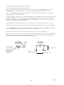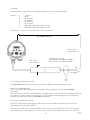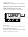
1
Instruction & maintenance leaflet
IP2046IM, Rev. AA
November 2006
MSP400RH
Mobrey
MSP400RH Series
Level Transmitter
www.mobrey.com
1
IP2046/IM
Nov 2006
CONTENTS
Page
1.
Introduction
3
2.
2.1
2.2
2.3
The MSP400RH ultrasonic level transmitter
Type numbering system
Pressure Equipment Directive
Specifications
3
3
4
4
3.
3.1
3.1.1
3.1.2
3.1.3
3.1.4
3.2
3.3
3.4
Installation
Location of the MSP400RH transmitter
General considerations
Liquid surface conditions
In-tank / well effects
Open Channel Flow installations
Mounting the transmitter above the liquid surface
Wiring
Additional components in the 2 wire loop
6
6
6
7
8
8
10
11
12
4.
4.1
4.2
4.3
4.4
4.5
4.6
4.7
Commissioning / Programming
Display & push buttons
Power up
Programming - important notes
Setting up for the chosen application
Diagnostic data
Loop Test
Engineering Set-up menu
13
13
14
14
15
27
28
29
5.
Maintenance
35
Appendices
Appendix A1
Appendix A2
Appendix A3
Appendix A4
Appendix B
Appendix C
Appendix D
Main Menu - Programming
Diagnostic Menu
Commissioning / Loop test menu
Engineering menu
Default menu listing
Listing of non-linear profiles in the MSP400
Hart Communications with the MSP400
36
38
39
40
41
43
44
The MSP400 transmitter is a measuring instrument
and should be handled with due
care and attention at all times
Footnote :In this manual the following terms are used which refer to trademarks from other manufacturers:
HART: is the protocol adopted for the MSP400 SMART Communications.
HART is a registered trademark of the HART Communications Foundation and is a mnemonic For
Highway Addressable Remote Transducer.
2
IP2046/IM
Nov 2006
1.0 Introduction
The MSP400 ultrasonic level transmitter is designed to be mounted above a liquid and will measure the
distance to the liquid surface.
When programmed with details of the vessel, sump or open channel, the MSP400 will compute level,
contents or flow and give a 4-20mA signal proportional to the chosen variable. 2 relays are provided for
control functions. Programming is achieved using integral push buttons or by remote communication
using HART protocol.
MSP400 is a two wire 24V dc loop powered transmitter and may be connected to any suitable dc power
source using 2 core shielded cable. The Mobrey MCU900 range of Control Units is designed to
be used with the MSP400 transmitter in this way.
The MSP400 transmitter must not be mounted in a hazardous area, even if supplied from a protected
power supply.
2.0 The MSP400RH ultrasonic level transmitter.
The transmitter operates over a range of 0.45m to 11m. When powered up the transmitter will give a
4-20mA signal on the two wire power cable over the factory default range :
4mA at 11m; 20mA at 0.45m. This range may be adjusted during commissioning. See section 4.0
Models covered in this manual :
MSP400RH - B28
MSP400RH - N28
The transmitter is mounted using the 2” thread provided. An optional mounting bracket kit is available
on request. MSP-BRK2 (2” BSPT) or MSP-BRK3 (2” NPT).
2.1 Type numbering system
MSP Mobrey ultrasonic level transmitter
400R 11m operating range, 2 relay outputs
H
HART communications
-B28 2” BSPT mounting, PVDF wetside
-N28 2” NPT mounting, PVDF wetside
3
IP2046/IM
Nov 2006
2.2 Pressure Equipment Directive
The MSP400RH transmitter does not fall within the PED definition as enclosing a pressurised fluid, so is
therefore outside the scope of the Directive.
Accordingly, the Declaration of Conformity does not list the Pressure Equipment Directive.
2.3 Specifications
Materials of construction:
Transducer material
Body & cover Material
Cable gland
Cover seal
Cover screws
Transducer bodyseal
PVDF
Glass filled nylon
Nylon with Nitrile cable seal
Silicone rubber
316 Stainless Steel
EPDM
Electrical
Supply voltage
12-40V dc
Output
4-20mA (3.8 - 20.5mA linear)
Relays (2) : SPST rated 1A at 24Vdc
HART Digital communications (Rev. 5)
None required
Two core each 0.22 mm2 min, shielded
3000m
0.1 Ohm per metre length max.
Suitable for cable sizes 4mm - 8mm diameter
Communications
Earthing
Recommended Cable
Max. cable length
Cable resistance
Cable gland
Operating
Range
Temperature
Ambient
Wetside
Pressure
Weatherproofing
0.45 to 11m
-40°C to +70°C
-30°C to +70°C
-0.25 bar to 3.0 bar
IP66/IP67
Certification
The MSP400 range of products are Factory Mutual (Fm) certified as Process Control Equipment meeting
basic electrical, mechanical and fire protection requirements (IP66/IP67).
4
IP2046/IM
Nov 2006
-40 / +158°F
Ø 144 (5.7")
-40 / +70°C
IP66 / IP67
Ambient
2 x M20 conduit connections
1 x cable gland
1 x blanking plug
135
(5.3")
60mm A/F (2.4")
65
(2.6")
MSP400RH-B28 : 2" BSPT
MSP400RH-N28 : 2" NPT
-30 / +70°C
-22 / +158°F
-0,25 / +3,0bar
-4 / +44psi
MIN : 0.45m (18”)
MAX : 11.0m (433”)
Wetside
b.rEF
5
IP2046/IM
Nov 2006
3.0 Installation
Important safety notice : The MSP400 is designed for safe area use only, and must not be installed in a
hazardous area, even if the power is supplied through a barrier device.
General
a.
b.
Installation must be carried out by suitably trained personnel in accordance with the
applicable code of practice.
If the equipment is likely to come into contact with aggressive substances, it is the
responsibility of the user to take suitable precautions that prevent it from being adversely
affected, thus ensuring that the type of protection is not compromised.
Aggressive Substances – e.g. acidic liquids or gases that may attack metals or solvents that may
affect polymeric materials.
Suitable Precautions – e.g. regular checks as part of routine inspections or establishing from the
material’s data sheet that it is resistant to specific chemicals.
c.
The equipment should only be cleaned with a damp cloth, do not use solvents.
d.
The equipment is not intended to be repaired by the user and is to be replaced by an
equivalent certified unit. Repairs should only be carried out by the manufacturer or
approved repairer.
3.1 Location of the MSP400RH transmitter
Correct location of the transmitter is essential for the reliable operation of any ultrasonic level
measurement system.
Whilst the transmitter may be site tuned to deal with most application conditions, it is strongly
recommended that the following guidelines should be adopted wherever relevant.
3.1.1 General considerations
•
The MSP400RH transmitter complies with the European Directive for Electro Magnetic Compatibility
(EMC) Class B.
It is not advisable to mount the transmitter in close proximity to a source of electrical noise such as a
variable speed drive or other high powered electrical device.
•
The MSP400 should be mounted above the liquid surface using the “2” thread provided. To
facilitate mounting, a bracket kit is available. See Section 3.2.
Note : The MSP400 is designed to be mounted in a non-metallic fitting or flange. The use of
metallic fittings or flanges is not recommended.
•
The transmitter should be mounted as near vertical as possible to ensure a good echo from the liquid
surface and maximum echo size received.
The beam angle (to the half power point) of the transmitter is 12 degrees inclusive.
Obstructions in the tank or well may generate echoes which can be confused with the real liquid
surface echo. Obstructions within the beam angle generate strong “false-echoes”; wherever possible,
the transmitter should be positioned such that false echoes are avoided.
To avoid detecting unwanted objects in the tank or well, it is advisable to maintain a distance of at
least 0.11m from the centre line of the transmitter for every metre range to the obstruction.
•
If the transmitter is located near the side of the tank or well, there will be no false echo generated
provided the wall is smooth and free of protrusions. However, there will still be a reduction in the
echo size. To avoid large echo size loss, it is recommended that the transmitter never be mounted
closer than 0.3m to the wall.
Fatty, dirty or viscous liquids can cause a “scum line” to build-up on the tank or well wall. Avoid false
echoes from this by enabling “scum line prevention” software in the MCU control unit.
6
IP2046/IM
Nov 2006
Max 3°
(1.3"/ft)
i.e.
0,11m/m
C
D Min = 0.45m (18”)
D Max = 11m
(433”)
C
= 0.3m (12”) min to 0.88m (36”)
D
•
If the transmitter is mounted in an enclosed tank, avoid mounting the transmitter in the centre of the
tank roof as this could act as a parabolic reflector and create unwanted echoes. Avoid applications
where heavy condensation could form on the transducer face.
•
If the transmitter is mounted in a stand-off or nozzle, it is always preferable that the transmitter face
be at least 5mm proud of the stand-off such that it protrudes beyond the stand-off and into the tank.
If this is not possible, see section 3.2.
•
If the transmitter is used in environments where direct sunlight can cause very high surface
temperatures on exposed instruments, it is recommended that the installer should construct a
suitable sun-shade to protect against this.
•
Remember that the minimum operating range of the transmitter is 0.45m. The transmitter will not
detect any liquid surface closer than 0.45m to the transmitter face.
3.1.2 Liquid surface conditions
•
Foaming liquids can reduce the size of the returned echo as foam is a poor ultrasonic reflector. It is
always preferable to mount an ultrasonic transmitter over an area of clear liquid, such as near the
inlet to a tank or well. In extreme conditions, or where this is not possible, the transmitter may be
mounted in a vented stilling tube provided that the inside bore of the stilling tube is at least 100 mm
(4”) and is smooth and free from joints or protrusions. It is also preferable that the bottom of the
stilling tube does not become uncovered, thus preventing the ingress of foams.
•
Beware of mounting the transmitter directly over any inlet stream.
•
Liquid surface turbulence is not normally a problem unless it is excessive. In most cases, the effects
of turbulence are minor, with excessive turbulence being catered for by fine tuning the transmitter on
site if necessary.
7
IP2046/IM
Nov 2006
3.1.3 In-tank effects
•
Stirrers or agitators can cause a vortex. Always try to mount the transmitter off-centre of any vortex to
maximise the return echo.
As stirrer blades become uncovered they will create echoes as they pass through the ultrasonic beam.
The transmitter can be tuned to ignore these false echoes on site.
•
In non-linear tanks with rounded or conical bottoms, always mount the transmitter off-centre. In some
cases, it may be desirable to install a perforated reflector plate on the tank bottom directly under the
transmitter centre line to ensure a satisfactory return echo.
•
Avoid mounting the transmitter directly above any pumps as the transmitter will detect the pump
casing as the liquid falls away. If this is not possible, fine tuning on site may be required to ignore
echoes from the pump casings.
3.1.4 Open Channel Flow installations.
There are normally two distinct parts to an open channel flow measurement system; the primary element
(flow structure) and the secondary element (Head measurement instrumentation).
For accurate open channel flow measurement, both parts of the system must be installed accurately.
This manual explains some key aspects of the installation of the secondary element, in this case the
ultrasonic transmitter.
For full details of the installation of a primary element such as a flume or weir, reference should be made
to the relevant British (BS3680) or International standard.
In the United Kingdom, Mobrey Ltd offers a complete installation and commissioning service for
open channel flow measurement systems. For further information contact the sales office and/or refer to
Mobrey’s ‘The Guide’.
Positioning of the transmitter is critical and should be the correct distance upstream from the flow
structure as stated in BS3680 e.g. a distance of 4 to 5 times Hmax for a thin plate weir or 3 to 4 times
Hmax for a flume.
For optimum accuracy, the front face of the transmitter should be positioned at a height that is at least
equal to the maximum flow depth plus the blanking distance of the transducer. A minimum distance of
0.46m is recommended.
Hmax + 0.46m
Hmax
It is important to note that the bottom reference of the transmitter should be related to the centre of the
invert of the primary device, NOT the distance to the channel bottom directly below the transmitter.
8
IP2046/IM
Nov 2006
Transmitter
front face
Flow
Channel invert
Primary device (eg.
flume, weir) invert
In addition to the above, when setting the bottom reference on a ‘V’ notch weir it is important that the
true invert of the weir is taken and not the meniscus liquid level, which may be 3 to 4mm (1/8”) above
the true invert.
Transmitter bottom
reference
Meniscus
True invert
•
The liquid surface at the point of measurement must have a stable, smooth surface and uniform
approach velocity. It must not be affected by baffles, foam, hydraulic jumps or any other object
likely to cause flow disruption.
•
The primary element should be free from any situation where it is likely to ‘drown’ (refer to relevant
standard for further information)
•
The MSP400RH transmitter has integral temperature compensation and must be protected at all
times from direct sunlight and any radiated heat.
For maximum accuracy and stability of level measurement reading the transmitter should always be
shrouded to prevent the incidence of direct sunlight.
If the flow structure permits, mount the transmitter within the flow channel or chamber.
Alternatively, the MSP400RH transmitter can accept an input from an external temperature sensor.
See section 3.3.1.
If you are in doubt about any aspect of transmitter installation, contact Mobrey (Service
Division) who will be pleased to advise.
9
IP2046/IM
Nov 2006
3.2 Mounting the transmitter above the liquid surface.
A 2” thread is provided to mount the transmitter.
The user should check the thread form, which will be either 2” BSPT (MSP400RH-B28) or 2” NPT
(MSP400RH-N28). The thread form is clearly marked on the hexagon of the transducer body.
Note : The MSP400 is designed to be mounted in a non-metallic fitting or flange. The use of metallic
fittings or flanges is not recommended.
To help installation, a bracket kit is available from Mobrey. This comprises a Stainless Steel angle bracket
and PVC threaded disc which may be used to mount the MSP400 on a gantry or other support over the
liquid level. Order part number MSP-BRK2 (BSP) or MSP-BRK3 (NPT). The bracket may be bolted to a
suitable cross member above the liquid surface.
Ensure that the transmitter is perpendicular to the liquid surface to maximise the return echo size.
Check that the maximum liquid level will not encroach into the 0.45m blanking zone of the transmitter.
Note : To aid alignment, the echo size / signal strength can be displayed on the MCU900 control unit or
on the MSP400RH transmitter display. Refer to section 4 for details.
Use PTFE tape on the screw thread, tighten to hand tight + ¼ turn, using the Hexagon.
When installing on a vessel which has a nozzle or stand-off, and the transducer face does not protrude into
the vessel, note the dimensions in the diagram below and always ensure that the nozzle/vessel weld is
smooth and free from internal weld beads or other projections.
PTFE
(Teflon)
Use hexagon to
tighten to hand
tight + ¼ turn
DO NOT USE
HOUSING TO
TIGHTEN.
Max : 0,35m (14")
Min :
R3,0mm (1/8")
10
Min 0,15m (6")
IP2046/IM
Nov 2006
3.3 Wiring
The transmitter is supplied with cable gland suitable for cable sizes 4-8mm diameter.
Terminal
1
2
3
4
5
6
7
8
:
:
:
:
:
:
:
:
+24V dc
0v dc
RL1 (SPST)
RL1 (SPST)
RL2 (SPST)
RL2 (SPST)
MSP-RTP temperature probe (if used)
MSP-RTP temperature probe (if used)
Earth Screen : Connect to a standard earth in the control room.
Max 3000m (9845ft)
Earth screen in
control room only
Twisted pair, screened
Min 0,22mm2 (25 SWG / 24 AWG)
Max 1,5mm2 (17 SWG / 15 AWG)
Ø 4 - 8mm
(0.15 - 0.31")
0V
+12-40V dc
3.3.1 External temperature sensor
The MSP400RH transmitter will accept an input from a Mobrey external temperature sensor.
Order part number MSP-RTP.
This is a thermistor based temperature sensor specifically designed for use with the MSP400RH
transmitter.
Full installation instructions are supplied with the temperature sensor, but note that it should be mounted
out of direct sunlight in a position such that it can give a representative reading of the air temperature
between the liquid surface and the MSP400RH transmitter.
3.3.2 After completing the wiring
Ensure all cable glands / blanking plugs and seals are in good condition after wiring to maintain the
weatherproof rating of the transmitter.
Check that the cover seal is in good condition and not twisted or misaligned in the seal location groove.
When replacing the cover, tighten the 3 cover screws evenly to exert uniform pressure on the cover seal.
11
IP2046/IM
Nov 2006
3.3.3 Relays
The MSP400RH transmitter has 2 integral relays which may be used for control purposes. These relays
are light duty and should be used as signal relays only, with control functions being performed by external
control relays.
Relay 2 is defaulted as a ‘fault’ relay, normally energised, but may be reconfigured on site as a set point
relay if required.
3.4 Additional components in the two wire loop.
3.4.1 Lightning / surge protection and other loop devices
It is allowable to fit loop powered or separately powered devices in the two wire loop provided that the
transmitter receives a minimum voltage of 12V dc at 21 mA loop current.
If the area is prone to lightning strikes or voltage surges, fitting of a suppressor device is desirable
between the transmitter and the control unit.
3.5 Wiring to allow HART communication
If it is intended to use HART digital communications with the MSP400RH transmitter, a 250 Ohm 0.25W
load resistor must be installed in the loop.
When used with the Mobrey MCU900 family of Control Units, there is no need to install an
external load resistor in the loop as there is a suitable resistor built in to the Control Unit.
If the transmitter is being supplied through a safety barrier, ensure the type chosen will pass HART/
SMART information.
Once installed, a HART communicator can be connected across the load resistor, or across the loop at
any point downstream of the load resistor.
12
IP2046/IM
Nov 2006
4.0 Commissioning, programming and operation
The MSP400 operates from a menu of parameters, each held in a specific memory location within the
instrument. The memory locations may be pictured as a matrix, and the user navigates to each parameter
to programme the instrument using ↓ and → steps.
Refer now to the Main Menu structure shown in Appendix A
The MSP400 leaves the factory pre-programmed with a value in each parameter location such that , when
the power is first applied, the instrument will give a sensible reading. A list of default values is given in
the parameter listing in Appendix B.
The MSP400 is HART enabled, allowing remote communications with the instrument.
The instrument can therefore be either programmed using a suitable HART compatible master, or may be
programmed locally using the push buttons provided inside the instrument. For details of local
programming, continue reading this section. For details of HART communications, refer to Appendix D.
4.1 Display and push buttons.
D
L
C
F
Alarm
Fault
gal/m 3 /hrft 3 /hringal/s @max
↓
Button Colour :
Green
↵
→
Blue
Red
The main display allows display of up to 5 characters, which in the normal run mode will be the
measurement, termed the Primary Variable (PV) of the instrument, or in the programming mode will be
data to assist in programming.
To the left of the main display are 4 arrow icons, only one of which will be illuminated at any one time to
indicate the duty chosen by the user.
To the right of the main display are 2 arrow icons which indicate the status of the transmitter relays.
When illuminated, they indicate that the relay contact is closed.
Under the main display is a text string which allows display of the units of measurement. The instrument
will illuminate only those characters applicable to the units of measurement chosen.
To the right of the text string is an echo received icon made up of 3 arc segments which continuously
indicate the strength of the echo received (minimum, average and good)
13
IP2046/IM
Nov 2006
4.2 Power up
On power up, the MSP400 will take a few seconds to initialise. The display will run through a set-up
routine, first illuminating all display characters then showing the software revision number. Once checks
are complete, the display will show the Primary Variable (PV) determined based upon the factory default
values in the memory.
On a new instrument aimed at a good target, this will be what the MSP400 calculates as a level reading
based upon the default value for the bottom reference.
The duty icon against the letter L on the top plate and the RL2 icon will be illuminated.
It is possible that the RL1 icon may be illuminated depending upon the level calculated by the MSP400
at this time.
The MSP400 is now ready for use, and the next step is to programme the unit with details of the
application.
The MSP400 may be programmed either in-situ or prior to installation. All programmed data is retained in
the MSP400 memory after power off.
4.3 Programming- Important notes to help you programme the MSP400
•
Do not allow rain or water to enter the MSP400 whilst programming or damage to the circuit boards
will occur.
•
Use the push buttons as instructed below to navigate through the programming menu and select or
enter application data.
It is recommended that use of the push buttons is firm but not overly so to prevent damage to the
circuit boards below, and that the user should not press buttons too fast to avoid incorrect data entry.
Simply holding down the green button ↓ will automatically scroll through any option list without the
need for repeated pressing of the button.
•
Pressing the red button ↵ at any time will step the user back to the previous level in the menu.
Note, if the red button ↵ is pressed after a menu option selection has been made or new data has
been entered, this option selection or new data will automatically be saved.
•
Whilst programming should be simple and intuitive, it may be that the user wishes to start again or
may wish to clear the memory of site entered data from a previous application. The MSP400 has a
“re-set default values” routine which allows the user to reload the MSP400 memory with the factory
default values as shown on the menu structure. Refer to section 4.7.10.
14
IP2046/IM
Nov 2006
4.4 Setting up for the chosen application - the Main Menu.
Refer now to the main menu structure chart in Appendix A.
It is important to note that MSP400 programming is most easily accomplished by first selecting the duty
the transmitter is to perform.
Once a duty is selected (see section 4.4.1), a “mini-wizard” programming assistant is invoked and the
user is thereafter only asked for information relevant to the duty chosen. As the user is guided through the
menu, data input allows the mini-wizard to populate relevant parameters with application specific data in
the background, and then select the next step required to configure the transmitter for the chosen
application.
The user is strongly advised to enter the duty menu whenever programming the MSP400, thus invoking
the mini-wizard which will assist programming.
Once programmed, it is possible to review the data entered into or calculated by the MSP400 by stepping
through the main menu using the green button ↓.
Note however that this will be a manual navigation of the MSP400 menu, and that all menu items will be
shown in this procedure, regardless of the duty chosen; the mini-wizard is only invoked if the user enters
and scrolls through or selects/refreshes a duty choice.
In a manual navigation down the main menu, simply ignore those menu items shown that do not relate to
your application.
4.4.1 Selecting the duty:
Screen display:
Factory default setting:
dutY
Level
The MSP400 may be programmed to perform one of 4 duties:
•
•
•
•
Distance measurement
Level measurement (factory default setting)
Flow measurement
Contents measurement
To change the duty:
a) Press the green button ↓ to display the “dutY” menu entry screen.
b) To confirm or change the duty from Level to one of the other duties, thus invoking the mini-wizard,
press the blue button → to enter the “dutY” menu. Press the blue button → again to allow change of
the duty. The current duty will now be flashing, indicating it may be confirmed or changed.
c) Press the green button ↓ to scroll through the list of available duty options, or press the red button ↵ if
the duty displayed is correct
d) Once the desired duty is shown (flashing) on the display, press the blue button → to select this duty. It
will now stop flashing.
e) If the chosen duty is incorrect, the edit sequence for the duty can be re-started by pressing the blue
button → again.
If the chosen duty is correct, press the red button ↵ to save the duty to memory and automatically
scroll on to the next main menu option: units.
Note that the arrow icon to the left of the display will now show the duty chosen and saved.
15
IP2046/IM
Nov 2006
4.4.2 Selecting the units of measurement
Screen display:
Factory default setting:
MSP400RH-B28
MSP400RH-N28
unitS
m
ft
i) Note that the factory default units of measurement are dictated by the model type, which may be
Imperial (ft) or Metric (m).
The user can reconfigure a Metric unit to be an Imperial or vice-versa by changing the base units (b.unit)
of the MSP400 - refer to section 4.7.11
ii) Note that changing the base units will cause the MSP400 to re-start with factory default values in all
other parameters.
Changing base units after programming the MSP400 will cause all programmed data to be overwritten
with factory default values.
The MSP400 is pre-programmed with selected units of measurement for each of the duties available :
•
Distance and Level measurement
m,
ft,
in,
none
•
Flow measurement
l/s,
l/m,
m3/hr,
gal/s,
Contents measurement
l,
m3,
gal,
ft3
•
gal/m,
ft3/m (cfm),
ft3/hr,
none
To change the units of measurement:
a) Press the green button ↓ to display the “unitS” menu entry screen. If metres are the chosen units of
measurement, as indicated by the small “”m” below the word “unitS” press the green button ↓ to
continue commissioning.
b) To change the units of measurement from metres to one of the other options, press the blue button →
to enter the “unitS” menu. Press the blue button → again to allow change of the units of
measurement. The current unit of measurement will now be flashing, indicating it may be changed.
c) Press the green button ↓ to scroll through the list of available duty options.
Notes.
i) The MSP400 will offer a selection of units of measurement relevant to the chosen duty as shown in the
option table above.
The final option in each set is “none”, which appears as a blank screen. This option is available to the
user who requires to display in units other than those available in the standard option table. In this case,
the user will need to scale the PV according to a suitable scaling factor - refer to section 4.4.6
It is strongly recommended that the user make a note of the scale factor and the resultant units of
measurement and retain this on a label within the instrument at all times to avoid later confusion.
ii) When using the green button ↓ to scroll through the units of measurement options, allow 2-3 seconds
after each button press for the MSP400 to check and display the selection. Pressing the green button ↓
continuously simply continues scrolling around the units of measurement option loop.
d) Once the desired unit of measurement is shown (flashing) on the display, press the blue button → to
select this option. It will now stop flashing.
e) If the chosen units of measurement are incorrect, the edit sequence for the units of measurement
can be re-started by pressing the blue button → again.
If the chosen units of measurement are correct, press the red button ↵ to save the units of measurement
to memory and automatically scroll on to the next main menu option: b.rEF.
16
IP2046/IM
Nov 2006
4.4.3 Setting the correct bottom reference
Screen display:
Factory default value:
MSP400RH-B28
MSP400RH-N28
b.rEF
11
36
The MSP400 leaves the factory with the bottom reference pre-programmed to the maximum range of the
instrument, either 11m or 36ft.
20/4
ullage
b.rEF
4/20
liquid
level
To change the bottom reference:
a) Press the green button ↓ to display the current “b.rEF” menu entry screen.
b) Press the blue button → to enter the “b.rEF” menu and to display the current bottom reference in use.
It is quite unlikely that the factory default value for bottom reference will suit your application.
To edit the bottom reference, press the blue button → to enter the editing mode.
The leading digit of the current bottom reference will now be flashing, indicating it may be changed.
c) Use the green button ↓ to edit the value of the leading digit.
Be careful not to enter a value greater than the maximum range of the MSP400: 11m or 36ft.
The value of the leading digit should therefore be 1 or 3 as a maximum, depending upon the units of
measurement chosen earlier.
Once correct, use the blue button → to select the next digit and then the green button ↓ to edit as before,
or the blue button → to move to the next digit. Continue this sequence until all 5 digits are correct.
d) Press the blue button → a final time to confirm the new value. None of the digits should now be
flashing.
e) If the new bottom reference value is incorrect, the edit sequence for the bottom reference can be restarted by pressing the blue button → again.
If the new bottom reference is correct, press the red button ↵ to save the new value to memory and
automatically scroll on to the next main menu option:
Note:
If the user has chosen a duty of Flow or Contents, the next menu option offered will be “ProF”. Refer now
to sections 4.4.4 to 4.4.9.
If the user has chosen a duty of Level or Distance, the next menu option offered will be “4”. Skip
sections 4.4.4 to 4.4.9 and refer now to section 4.4.10.
TIP: a feature of the MSP400 useful at this stage is that it can be used as an electronic tape measure.
With an empty tank or vessel, select Distance as the duty and the MSP400 will read the distance to
the bottom of the tank. This can be noted and used when setting b.rEF
17
IP2046/IM
Nov 2006
4.4.4 Selecting the correct Profile algorithm.
Screen display:
Factory default value:
ProF
Linear
This selection is offered only if the user has chosen a duty of Flow or Contents, or is shown when
manually navigating the main menu - ignore if duty chosen is Level or Distance.
The MSP400 is pre-programmed with a selection of popular profiles which are mathematical formulae to
convert a linear level reading to a flow or volumetric PV.
Once converted, the 4-20mA and the display of the unit will operate according to the flow or
volumetric PV.
The options available are described in the following sections:
4.4.4.1 Flow measurement
3/2
5/2
mann
PAr 1
PAr 2
PAr 3
PAr 4
PAr 5
PAr 6
PAr 7
PAr 8
FF01
:
:
:
FP07
Flume 3/2 flow law
V-Notch 5/2 flow law
Manning formula
1 ft Parshall flume
2 ft Parshall flume
3 ft Parshall flume
4 ft Parshall flume
5 ft Parshall flume
6 ft Parshall flume
7 ft Parshall flume
8 ft Parshall flume
Flume Flat 1
Flume Parabolic 7
The last 30 options for flow FF01 - FP07 comprise a selection of pre-defined standard
flow structures which may be of use if none of the other profiles suit. Refer to Appendix
D for details.
Note, when scrolling around the profile option loop, all flow and contents profiles are shown.
There are two other profiles which are available but which are not visible when
programming the MSP400 using the push buttons.
SPEC. P
Special plotted : only used if the MSP400 has been configured by a HART master such as
the Mobrey MCU900 series controller or Mobrey H-Conf401 software
SPEC.C
Special calculated : used when a standard profile is not available from the MSP400 library.
Allows the user to enter a Power law and a K factor, for example for a small Parshall flume or
to modify the K factor or power to allow for imperfections in standard flow structures.
To change the flow profile:
a) Press the green button ↓ to display the “ProF” menu entry screen.
b) Press the blue button → to display the current selection. If this selection is correct, press the red
button ↵ to return to the main menu.
c) To change the profile to one of the other options, press the blue button → to enter the “ProF” menu.
The current selection will now be flashing, indicating it may be changed.
d) Press the green button ↓ to scroll through the list of available profile options, as given in the table
above.
18
IP2046/IM
Nov 2006
Note: The complete range of options is displayed, regardless of the duty selected earlier.
e) Once the desired profile is shown (flashing) on the display, press the blue button → to select this
option. It will now stop flashing.
f)
If the chosen profile is incorrect, the edit sequence for the profile selection can be re-started by
pressing the blue button → again.
If the profile is correct, press the red button ↵ to save the profile to memory and automatically scroll on
to the next main menu option.
Note:
The next menu item presented will depend upon the flow profile chosen :i)
3/2 5/2 : the next menu item will be “SCALE”
The MSP400 will automatically calculate the Power factor and only requies the K factor to be
entered.
Refer to section 4.4.6
ii)
Manning : the next menu item will be “LEUEL @ max”.
Refer to section 4.4.7.
iii)
Parshall, FF or FP : the next menu item will be “d”. The MSP400 will automatically calculate the
appropriate Power factor and K factor, and will set the 4mA point at zero flow and the 20mA point
at maximum flow.
Refer to section 4.4.12.
4.4.4.2 Contents measurement
Lin
H.CYL.F
SPH.
H.CYL.D
Linear (factory default setting)
Horizontal cylinder on it’s side with flat ends
Spherical vessel
Horizontal cylinder on it’s side with dished ends
To change the contents profile:
a) Press the green button ↓ to display the “ProF” menu entry screen.
b) Press the blue button → to display the current selection. If this selection is correct, press the red
button ↵ to return to the main menu.
c) To change the profile to one of the other options, press the blue button → to enter the “ProF” menu.
The current selection will now be flashing, indicating it may be changed.
d) Press the green button ↓ to scroll through the list of available profile options, as given in the table
above.
Note: The complete range of options is displayed, regardless of the duty selected earlier.
e) Once the desired profile is shown (flashing) on the display, press the blue button → to select this
option. It will now stop flashing.
f)
If the chosen profile is incorrect, the edit sequence for the profile selection can be re-started by
pressing the blue button → again.
If the profile chosen is “Lin”, press the red button ↵ to save the profile to memory and automatically
scroll on to the next main menu option “SCALE”.
Refer to section 4.4.6.
19
IP2046/IM
Nov 2006
If the profile chosen is any other contents profile, press the red button ↵ to save the profile to memory
and automatically scroll on to the next main menu option “Cont @ max”, Refer to Section 4.4.9.
4.4.5 Power factor for the chosen flow law.
Screen display:
Factory default value:
P.FACt
1.000
This selection is offered only if the user has chosen a duty of Flow which requires the manual entry of a
power factor in a formula of the type
Flow Q = kh*
(where * = the power factor)
or is shown when manually navigating the main menu - ignore if duty chosen is Level, Distance or
Contents.
The MSP400 is pre-programmed with the appropriate power factor for many of the flow profile options
available, or it may be edited to suit the user’s specific flow structure.
Refer to Appendix C for a table of pre-programmed values.
To edit the power factor
a) Press the blue button → to enter the “P.FACt” menu and to display the current power factor in use. If
this is correct, press the green button ↓ return to the main menu.
If the power factor is to be edited, press the blue button → again to allow editing
The leading digit of the current power factor will now be flashing, indicating it may be changed.
b) Use the green button ↓ to edit the value of the leading digit.
c) Once correct, use the blue button → to select the next digit and then the green button ↓ to edit as
before, or the blue button → to move to the next digit. Continue this sequence until all 5 digits are
correct.
d) Press the blue button → a final time to confirm the new value. None of the digits should now be
flashing.
If the new power factor value is incorrect, the edit sequence for the power factor can be re-started by
pressing the blue button → again.
If the new power factor is correct, press the red button ↵ to save the new value to memory and
automatically scroll on to the next main menu option: “SCALE”
4.4.6 K Factor for the chosen flow law
Screen display
Factory default value
SCALE
1.000
Note:
The display will read “SCALE”. If a flow duty has been chose, the value entered into this parameter is in
effect the K factor in a flow law of the form Flow Q = kh*.
If a Distance, Level or Contents duty has been chosen, the value entered into this parameter is a factor
by which the measured distance, level or contents is scaled.
For a Level or Distance duty the scaling factor is normally left at the value calculated by the MSP400
depended upon previously entered data and the duty chosen, or the default value of 1.000, unless the user
wishes to convert the measurement to units other than those offered as standard, for example, yards.
For a linear Contents duty, the user must enter a scaling factor to convert the level measurement to a
contents measurement. If the units of measurements are “m”, then enter the volume contained in 1m of
liquid height in the tank. If the units of measurements are “ft”, then enter the volume contained in 1ft of
liquid height in the tank.
20
IP2046/IM
Nov 2006
To edit the scale factor
a) Press the blue button → to enter the “SCALE” menu and to display the current scale factor in use. If
this is correct, press the red button ↵ return to the main menu.
If the scale factor is to be edited, press the blue button → again to allow editing
The leading digit of the current scale factor will now be flashing, indicating it may be changed.
b) Use the green button ↓ to edit the value of the leading digit.
c) Once correct, use the blue button → to select the next digit and then the green button ↓ to edit as
before, or the blue button → to move to the next digit. Continue this sequence until all 5 digits are
correct.
d) Press the blue button → a final time to confirm the new value. None of the digits should now be
flashing.
If the new scale factor value is incorrect, the edit sequence for the scale factor can be re-started by
pressing the blue button → again.
If the new scale factor is correct, press the red button ↵ to save the new value to memory and
automatically scroll on to the next main menu option: “4”
However, if the data already entered allows the MSP400 to calculate the maximum flow, the 4mA and
20mA points are automatically set to 4mA at zero flow and 20mA at maximum flow.
The next menu item offered in this case is “d”.
Refer to section 4.4.11
4.4.7 Maximum level entry
Screen display
Factory default value
LEUEL@ max
1.000
This selection is offered only if the user has chosen a duty of Flow which requires entry of the level at
which the maximum flow occurs, or is shown when manually navigating the main menu - ignore if duty
chosen is Level, Distance or Contents.
To enter the value for the level at which the maximum flow occurs:
a) Press the blue button → to enter the “LEUEL” @ max” menu and press the blue button → again to
allow editing.
The leading digit of the level value will now be flashing, indicating it may be changed.
b) Use the green button ↓ to edit the value of the leading digit.
Once correct, use the blue button → to select the next digit and then the green button ↓ to edit as
before, or the blue button → to move to the next digit. Continue this sequence until all 5 digits are
correct.
c) Press the blue button → a final time to confirm the new value. None of the digits should now be
flashing.
d) If the new level value is incorrect, the edit sequence for the maximum level can be re-started by
pressing the blue button → again.
e) If the level value entered is correct, press the red button ↵ to save the value to memory and
automatically scroll on to the next main menu option: “Flo @ max”.
21
IP2046/IM
Nov 2006
4.4.8 Maximum flow entry
Screen display
Factory default value
Flo @ max
1.000
This selection is offered only if the user has chosen a duty of Flow which requires entry of the maximum
flow capability of the chosen structure (not the maximum flow expected in the application), or is shown
when manually navigating the main menu - ignore if duty chosen is Level, Distance or Contents.
To enter the value for maximum flow:
a) Press the blue button → to enter the “Flo @ max” menu and press the blue button → again to allow
editing.
The leading digit of the maximum flow will now be flashing, indicating it may be changed.
b) Use the green button ↓ to edit the value of the leading digit.
Once correct, use the blue button → to select the next digit and then the green button ↓ to edit as
before, or the blue button → to move to the next digit. Continue this sequence until all 5 digits are
correct.
c) Press the blue button → a final time to confirm the new value. None of the digits should now be
flashing.
d) If the new maximum flow value is incorrect, the edit sequence for the maximum flow can be re-started
by pressing the blue button → again.
e) If the maximum flow value entered is correct, press the red button ↵ to save the value to memory and
automatically scroll on to the next main menu option: “4”.
However, with a duty of Flow chosen if the data already entered allows the MSP400 to calculate the
maximum flow, the 4mA and 20mA points are automatically set to 4mA at 0 flow and 20mA at
maximum flow.
The next menu item offered in this case is “d”.
Refer to section 4.4.12.
4.4.9 Maximum contents entry
Screen display
Factory default value
Cont @ max
1.000
This selection is offered only if the user has chosen a duty of Contents which requires entry of the
maximum contents of the vessel, or is shown when manually navigating the main menu - ignore if duty
chosen is Level, Distance or Flow.
To enter the value for maximum contents:
a) Press the blue button → to enter the “Cont @ max” menu and press the blue button → again to allow
editing.
The leading digit of the maximum contents will now be flashing, indicating it may be changed.
b) Use the green button ↓ to edit the value of the leading digit.
Once correct, use the blue button → to select the next digit and then the green button ↓ to edit as
before, or the blue button → to move to the next digit. Continue this sequence until all 5 digits are
correct.
c) Press the blue button → a final time to confirm the new value. None of the digits should now be
flashing.
d) If the new maximum contents value is incorrect, the edit sequence for the maximum contents can be
re-started by pressing the blue button → again.
e) If the maximum contents value entered is correct, press the red button ↵ to save the value to memory
and automatically scroll on to the next main menu option: “4”.
22
IP2046/IM
Nov 2006
4.4.10 Setting the 4mA point
Screen Display:
Factory default value:
4
0.000
Enter the value of the PV which you require to be signalled by 4mA
The 4mA point may be set above or below the 20mA point to suit the monitoring or control equipment.
If you wish to set the 4 and 20mA points by ranging the MSP400 to a fixed target, such as the level in
the vessel at any particular time or a fixed target at a known distance away, skip these menu options now
by pressing the green button D 2 times to arrive at the set damping option.
To edit the 4mA point
a) Press the blue button → to enter the 4mA menu and to display the current value in use. If this is
correct, press the red button ↵ return to the main menu.
If the 4mA point is to be edited, press the blue button → again to allow editing
The leading digit of the current 4mA value will now be flashing, indicating it may be changed.
b) Use the green button D to edit the value of the leading digit.
c) Once correct, use the blue button → to select the next digit and then the green button D to edit as
before, or the blue button → to move to the next digit. Continue this sequence until all 5 digits are
correct.
If the new 4mA value is incorrect, the edit sequence for the 4mA point can be re-started by pressing the
blue button → again.
If the 4mA value is correct, press the red button ↵ to save the new value to memory and automatically
scroll on to the next main menu option: “20”
4.4.11 Setting the 20mA point
Screen Display:
Factory default value:
20
10.550
Enter the value of the PV which you require to be signalled by 20mA
The 20mA point may be set above or below the 4mA point to suit the monitoring or control equipment.
To edit the 20mA point
a) Press the blue button → to enter the 20mA menu and to display the current value in use. If this is
correct, press the red button ↵ return to the main menu.
If the 20mA point is to be edited, press the blue button → again to allow editing
The leading digit of the current 20mA value will now be flashing, indicating it may be changed.
b) Use the green button D to edit the value of the leading digit.
c) Once correct, use the blue button → to select the next digit and then the green button D to edit as
before, or the blue button → to move to the next digit. Continue this sequence until all 5 digits are
correct.
d) Press the blue button → a final time to confirm the new value. None of the digits should now be
flashing.
If the new 20mA value is incorrect, the edit sequence for the 20mA point can be re-started by pressing
the blue button → again.
If the 20mA value is correct, press the red button ↵ to save the new value to memory and automatically
scroll on to the next main menu option: “d”
23
IP2046/IM
Nov 2006
4.4.12 Setting the damping applied to the output
Screen display
Factory default value
d
3
The damping value entered is actually a time constant in seconds which is applied as smoothing to the
displayed PV and current output.
A new value may be entered up to a maximum value of 9999 seconds. A large value will have the effect
of smoothing out rapid changes of current output and will also smooth out the effects of turbulence and
ripples on the liquid surface.
Note, it would not normally be necessary to select a value greater than 30 seconds.
Alternatively, a value of zero may be entered in which case no smoothing is applied and changes in
reading immediately change the current output.
Note, as the MSP400 transmits a pulse at nominally once per second, a damping time of zero will not
necessarily give an immediate change in output.
To edit the damping value:
a) Press the blue button → to enter the damping menu and to display the current value in use. If this is
correct, press the green button ↓ return to the main menu.
If the damping value is to be edited, press the blue button → again to allow editing
The leading digit of the current damping value will now be flashing, indicating it may be changed.
b) Use the green button ↓ to edit the value of the leading digit.
c) Once correct, use the blue button → to select the next digit and then the green button ↓ to edit as
before, or the blue button → to move to the next digit. Continue this sequence until all the digits are
correct.
d) Press the blue button → a final time to confirm the new value. None of the digits should now be
flashing.
If the new damping value is incorrect, the edit sequence for the 20mA point can be re-started by pressing
the blue button → again.
If the damping value is correct, press the red button ↵ to save the new value to memory and automatically
scroll on to the next main menu option: “AL”
4.4.13 Selecting the output current action on alarm condition
Screen display
Factory default value
AL
Hold
The MSP400 will signal an alarm condition in the event that the target echo is lost for a period of 900
seconds or more. This time of 900 seconds is factory set and is changeable in the field.
(See Section 4.7.2)
The user can select what action the current output will take in the event of a lost echo condition:
Hi
The current on the two wire loop will drive up to 21mA and will remain there until a correct target
echo is recovered. The display will flash “LE” and the alarm action alternately.
Hold The current will freeze at the value it was last reading and will remain there until a correct target
echo is recovered. The display will flash “LE” and the last valid reading alternately.
Lo
The current on the two wire loop will drive down to 3.6mA and will remain there until a correct
target echo is recovered. The display will flash “LE” and the alarm action alternately.
24
IP2046/IM
Nov 2006
To change the output current action on alarm condition:
a) Press the blue button → to enter the alarm action menu and to display the current selection. If this is
correct, press the green button ↓ return to the main menu.
b) If the action is to be changed, press the blue button → again to allow editing
c) Press the green button ↓ to scroll through the list of available profile options, as given in the table
above.
d) Once the desired action is shown (flashing) on the display, press the blue button → to select this
option. It will now stop flashing.
e) If the chosen action is incorrect, the edit sequence for the profile selection can be re-started by
pressing the blue button → again.
If the action is correct, press the red button ↵ to save the action to memory and automatically scroll on
to the next main menu option.
4.4.14 Setting the relay on and off points
The MSP400 has two integral signal relays, each SPST format.
RL1 is a control relay by default. It may be set to energise at any value of PV and de-energise at any other
value of PV. Setting the on and off points to a common PV will turn the relay off. The on value may be
greater or smaller than the off value, and vice-versa.
RL2 is a fault relay by default. In this mode, it will de-energise under Lost Echo or system fault
conditions. This relay will also de-energise in the event the power fails.
The mode of RL2 may be changed to control mode by entering on and off values. In control mode, RL2
ceases to be a fault relay.
All relay set point values must be entered in the units chosen for the PV.
To set the on and off points for the relays:
a) Press the blue button → to enter the “r1 on” menu and to display the on PV value in use. If this is
correct, press the red button ↵ return to the main menu.
If the on PV value is to be edited, press the blue button → again to allow editing
The leading digit of the current on value will now be flashing, indicating it may be changed.
b) Use the green button ↓ to edit the value of the leading digit.
c) Once correct, use the blue button → to select the next digit and then the green button ↓ to edit as
before, or the blue button → to move to the next digit. Continue this sequence until all 5 digits are
correct.
d) Press the blue button → a final time to confirm the new PV value. None of the digits should now be
flashing.
If the new PV on value is incorrect, the edit sequence for the PV on value can be re-started by pressing
the blue button → again.
If the new PV on value is correct, press the red button ↵ to save the new PV on value to memory and
automatically scroll on to the next main menu option: “r1 OFF”
Repeat the sequence to edit the values for R1 off and R2 on and off values, or skip as appropriate.
Once correct, the next menu option offered will be “SEt 4”
25
IP2046/IM
Nov 2006
4.4.15 Setting the 4 and 20mA levels using actual liquid levels in the tank
Screen display
(SEt 4 & SEt 20)
Factory default value
Hold
If you have already programmed the 4 and 20mA levels as above, you do not need to enter this menu. All
the programming is now complete and you should press the red button ↵ to exit the programming menu
and return to the main PV display.
If, however, you wish to set the 4 or 20mA level by ranging the instrument to a known target – perhaps the
level in the vessel at this time – then press the blue button → to enter this menu.
To set the 4mA level
a) With the MSP400 aimed at a target a distance away equivalent to the 4mA level, press the blue →
button to display the value for the 4mA setting. Press the blue button → to allow setting, and the display
will alternately flash “4” with the current level reading.
b) Press blue button → to confirm the correct value for the 4mA level then press red button ↵ to save the
new value for the 4mA setting.
c) With the MSP400 aimed at a target a distance away equivalent to the 20mA level, press the blue →
button to display the value for the 20mA setting. Press the blue button → to allow setting, and the display
will alternately flash “20” with the current level reading.
d) Press blue button → to confirm the correct value for the 4mA level then press red button ↵ to save
the new value for the 20mA setting.
Programing of the MSP400 is now complete.
Check the main display to ensure the duty, units and PV are correct, and that relays are on or off
according to the set points programmed.
The cover may now be replaced, refer back to section 3.3.2
26
IP2046/IM
Nov 2006
4.5
Diagnostic data. See also Appendix A2.
The MSP400 can display useful diagnostic data which can aid setting up and fault finding.
To aid interpretation of the data presented, the data will alternate with suitable text to remind the user
what data is being displayed.
The user is not able to change or edit any of the data shown in the diagnostic section of the menu.
To enter the diagnostic menu, the user should press the blue button → from the main display screen to
display the text “diAg”. The following information is available:
4.5.1 Press the green button ↓ to display the distance to target in the chosen base units (m, ft, in) which
the MSP400 is measuring regardless of the duty chosen for the instrument.
Note:
Pressing the red button ↵ at any time will return the user to the top level “diAg” screen; pressing it again
will return the user to the main display screen
4.5.2 Press the green button ↓ to scroll down to the next diagnostic data “LEUEL”.
This is the level in base units, which the MSP400 has calculated based upon the bottom reference and
the distance measured, regardless of the duty chosen for the instrument.
4.5.3 Press the green button ↓ to scroll down to the next diagnostic data “Echo. S”.
This is the echo size being received on a scale of 0 to 100.
The user should aim to achieve a value of greater than 10, although the MSP400 will operate at
values below this.
4.5.4 Press the green button ↓ to scroll down to the next diagnostic data “Echo. n”.
This is the number of echoes being received and can be useful indicator of the data being
processed by the MSP400.
A thorough understanding of ultrasonic level systems is required to interpret this data.
4.5.5 Press the green button ↓ to scroll down to the next diagnostic data “F”.
This is the frequency in kHz at which the transducer is operating, and should read between 49 &
58.
4.5.6 Press the green button ↓ to scroll down to the next diagnostic data “t”.
This is the temperature which is being recorded by the integral temperature sensor and which is
being used by the transmitter in calculating distance to target, unless an external temperature
probe connected in which case it is the temperature being measured by the external probe.
4.5.7 Pressing the green button ↓ again will return the user to the start of the diagnostic menu.
The user may now press the red button ↵ to return the instrument to the normal operating mode
with the display showing the PV, or may press and hold the blue button → for at least 2 seconds to
move to the Loop Test menu.
27
IP2046/IM
Nov 2006
4.6
Loop Test : See also Appendix A3
“tESt”
The MSP400 has the facility to cycle through it’s programmed operating range without any change in the
liquid level, causing the current output and relays to cycle through their normal operation.
Also, the MSP400 can be programmed to fix the loop current at any desired value between 4 and 20mA
to allow testing of any other loop or control instruments.
To enter the loop test menu from the normal operating mode, press the blue button → to display “diAg”
then press and hold the blue button → for at least two seconds to display “tESt”.
4.6.1 Cycle function
“CyCLE”
a)
Press the green button ↓ to scroll down to the “CyCLE” menu.
b)
Press the blue button → to enter the cycle menu . The display will zero and show “0.0000 m”.
c)
Press the blue button → to initiate the cycle, and the MSP400 will cycle from the 4mA value to
the max PV value and back to the 4mA value again over about 100 seconds.
Pressing the green button ↓ at any time during the cycle will stop the cycle at that point. Press the
green button ↓ again to continue the cycle.
d)
Press the blue button → to return to the loop test menu and display “”CyCLE”.
4.6.2 Loop Current fixing
“LOOP”
a)
From the Loop test display “tESt” or the cycle display “CyCLE”, press the green button ↓ to scroll
to the “LOOP” menu.
b)
Press the blue button → to enter the LOOP menu, and the display will zero to show “0.000”.
c)
Press the blue button → to start an edit sequence which allows the user to enter a value for the
desired fixed loop current. Use the green button ↓ to change the digits in the normal manner.
d) Once the desired value is entered, press the blue button → to fix and display the loop current.
e) To change the fixed current value to a new value, press the blue button → to return to the LOOP menu
Pressing the green button ↓ again will return the user to the start of the Loop test menu.
The user may now press the red button ↵ to return the instrument to the normal operating mode with the
display showing the PV, or may press and hold both the blue → and the red ↵ buttons together for at least
2 seconds to move to the Engineering set-up menu.
28
IP2046/IM
Nov 2006
4.7
Engineering Set-up menu : See also Appendix A4
“Eng”
The proficient user is able to fine tune operation of the MSP400 if site or application conditions
are unusual.
Users are recommended to leave all operational fine tuning parameters at the factory default
settings unless they have a good understanding of the function and capability of the parameters.
The “reload factory defaults” function may be found within this menu, and should be used if the
transmitter has been configured incorrectly or if the user wishes to reset all parameter values
back to factory default values.
To display the Engineering set-up menu “Eng”, navigate from the normal PV display using the blue
button → and the red button ↵. Note the requirement to hold the button or hold two buttons
together as shown on the main menu in Appendix A.
To enter the “Eng” menu, press the green button ↓ to display the first menu item “t.HoLd”
4.7.1 Setting the Threshold
Screen display
Factory default value
“t.HoLd”
Auto
The threshold value is actually a limit below which false echoes are rejected.
Auto shows that the MSP400 will automatically set the threshold level for optimum performance based
on echo sizes being received.
A new value may be entered up to a maximum value of 99. A large value will have the effect of
eliminating false echo processing.
Note that the value shown is in the same units as echo size; if the wrong echo is being processed then
raising the threshold level above that of the false echo size (see 4.5.3) will allow the MSP400 to ignore
any echoes below this size, including the false echo itself.
To edit the threshold value:
a)
Press the blue button → to enter the threshold menu and to display the current value in use. If this
is correct, press the red button ↵ return to the main menu.
If the threshold is to be edited, press the blue button → again to allow editing
The leading digit of the 3 digit threshold value will now be flashing, indicating it may be changed.
b)
Use the green button D to edit the value of the leading digit.
c)
Once correct, use the blue button → to select the next digit and then the green button ↓ to edit as
before, or the blue button → to move to the next digit. Continue this sequence until all 3 digits are
correct.
d)
Press the blue button → a final time to confirm the new value. None of the digits should now be
flashing.
If the new threshold is incorrect, the edit sequence can be re-started by pressing the blue button → again.
If the threshold is correct, press the red button ↵ to save the new value to memory and automatically
scroll on to the next main menu option: “LE”
29
IP2046/IM
Nov 2006
4.7.2 Setting the Lost Echo Time
Screen display
Factory default value
“LE”
900
The lost echo time is the time in seconds which the MSP400 will wait before taking the lost echo action
as described in 4.4.13.
A new value may be entered in the range 0 to 9999. It is recommended that the lost echo time be left at
900 seconds to avoid false trips and alarms due to temporary loss of echo due to transient poor surface
conditions. A shorter lost echo time should only be programmed if it is imperative that action be taken in
a shorter timeframe.
To edit the lost echo time:
a) Press the blue button → to enter the lost echo time menu and to display the current value in use. If
this is correct, press the red button ↵ return to the main menu.
If the lost echo time is to be edited, press the blue button → again to allow editing
The leading digit of the lost echo time value will now be flashing, indicating it may be changed.
b) Use the green button ↓ to edit the value of the leading digit.
c) Once correct, use the blue button → to select the next digit and then the green button ↓ to edit as
before, or the blue button → to move to the next digit. Continue this sequence until all 4 digits are
correct.
d) Press the blue button → a final time to confirm the new value. None of the digits should now be
flashing.
If the new lost echo time is incorrect, the edit sequence can be re-started by pressing the blue button →
again.
If the lost echo time is correct, press the red button ↵ to save the new value to memory and automatically
scroll on to the next main menu option: “dEAd”
4.7.3 Setting the Dead Band
Screen display
Factory default value:
MSP400RH-B28
MSP400RH-N28
or
“dEAd”
0.45 (m)
1.5 (ft)
18 (in)
The dead band is the region below the MSP400 transmit face in which no measurements can be made.
This is also sometimes known as the Blanking or Blocking zone, and is a feature of all Ultrasonic level
transmitters, with a value dependant upon certain intrinsic properties of the transmitter itself.
The user should never reduce the dead band below the factory default minimum value unless advised to
do so by the manufacturer.
A larger value may be entered to elimate echo processing of echoes from false targets.
Note however, that any real echos in the dead band will also now be ignored.
30
IP2046/IM
Nov 2006
To edit the dead band:
a) Press the blue button → to enter the dead band menu and to display the current value in use. If this is
correct, press the red button ↵ return to the main menu.
If the dead band is to be edited, press the blue button → again to allow editing
The leading digit of the dead band value will now be flashing, indicating it may be changed.
b) Use the green button ↓ to edit the value of the leading digit.
c) Once correct, use the blue button → to select the next digit and then the green button ↓ to edit as
before, or the blue button → to move to the next digit. Continue this sequence until all digits are
correct.
d) Press the blue button → a final time to confirm the new value. None of the digits should now be
flashing.
If the new dead band is incorrect, the edit sequence can be re-started by pressing the blue button →
again.
If the dead band is correct, press the red button ↵ to save the new value to memory and automatically
scroll on to the next main menu option: “F”
4.7.4 Setting the Frequency
Screen display
Factory default value:
“F”
Auto
The frequency at which the MSP400 operates is automatically chosen by the microprocressor to ensure
optimum signal size and performance.
Auto shows that the MSP400 will automatically set the frequency to obtain the best echo size and
optimum performance. The actual frequency being used by the MSP400 can be viewed in diagnostics.
See 4.5.5
The limits of operating frequency are a function of the intrinsic properties of the transmitter itself.
The MSP400 may be set to operate at any frequency between 49 and 58 kHz
The transmit frequency directly affects the quality of the echo being received, which may be useful to
either improve a poor echo or reduce the quality of a false echo.
To change the frequency:
a) Press the blue button → to enter the frequency menu and to display the current value in use. If this is
correct, press the red button ↵ return to the main menu.
If the frequency is to be changed, press the blue button → again to allow editing
The frequency value currently in use will now be shown flashing on the display.
b) Use the green button ↓ to scroll through the options available (49 to 58 kHz).
c) Use the blue button → to select the chosen frequency.
If the new frequency is incorrect, the edit sequence can be re-started by pressing the blue button → again.
If the frequency is correct, press the red button ↵ to save the new frequency to memory and automatically
scroll on to the next main menu option: “Prf”
31
IP2046/IM
Nov 2006
4.7.5 Setting the Pulse repetition frequency
Screen display
Factory default value:
“Prf”
1.0
The rate of pulses transmitted by the MSP400 is set at a factory default value of once per second.
The MSP400 may be set to transmit faster or more slowly at selected repetition rates between 0.5 and
2.0 times per second.
The pulse repetition frequency may be changed to overcome cross talk problems if more than one
ultrasonic transmitter is mounted in the same tank.
To change the pulse repetition frequency:
a) Press the blue button → to enter the pulse repetition frequency menu and to display the current value
in use. If this is correct, press the red button ↵ return to the main menu.
If the pulse repetition frequency is to be changed, press the blue button → again to allow editing
The pulse repetition frequency value currently in use will now be shown flashing on the display.
b) Use the green button ↓ to scroll through the options available (0.5 to 2.0).
c) Use the blue button → to select the chosen pulse repetition frequency.
If the new pulse repetition frequency is incorrect, the edit sequence can be re-started by pressing the
blue button → again.
If the pulse repetition frequency is correct, press the red button ↵ to save the new pulse repetition
frequency to memory and automatically scroll on to the next main menu option: “Stir”
4.7.6 Setting a valid echo count
Screen display
Factory default value:
“Stir”
4
This parameter is normally used in vessels with a stirrer or agitator, particularly if it is slow moving, it is
possible for the MSP400 to detect uncovered blades and treat them as a valid echo, thus calculating an
incorrect level reading.
The MSP400 may be set to one of a list of pre-selected times in the range 1 to 100
Lowering = faster response
To change the valid echo count :
a) Press the blue button → to enter the stirrer menu and to display the current value in use. If this is
correct, press the red button ↵ return to the main menu.
If the valid echo count is to be changed, press the blue button → again to allow editing
The valid echo count currently in use will now be shown flashing on the display.
b) Use the green button ↓ to scroll through the options available (1 to 100).
c) Use the blue button → to select the chosen valid echo count.
If the valid echo count is incorrect, the edit sequence can be re-started by pressing the blue button →
again.
If the valid echo count is correct, press the red button ↵ to save the valid echo count to memory and
automatically scroll on to the next main menu option: “SPi”
32
IP2046/IM
Nov 2006
4.7.7 Setting the Spike rejection
Screen display
Factory default value:
“SPi”
0 (disabled)
In applications with high levels of acoustic or electrical noise, a spike could incorrectly trigger the echo
detection system. In such cases, the value of SPi can be increased (in the range 0-100) which has the
effect of rejecting such spikes. The user may have to try several different values to determine the best
option.
To change the spike rejection:
a) Press the blue button → to enter the spike rejection menu and to display the current value in use. If
this is correct, press the red button ↵ return to the main menu.
If the spike rejection is to be changed, press the blue button → again to allow editing
The spike rejection currently in use will now be shown flashing on the display.
b) Use the green button ↓ to scroll through the options available (1 - 100 in pre programmed steps)
c) Use the blue button → to select the chosen spike rejection.
If the new spike rejection is incorrect, the edit sequence can be re-started by pressing the blue button →
again.
If the spike rejection is correct, press the red button ↵ to save the new spike rejection to memory and
automatically scroll on to the next main menu option: “t”
4.7.8 Setting the Temperature
Screen display
Factory default value:
“t”
Auto
The MSP400 has to know the temperature of the air space through which it is sending pulses so that the
speed of sound can be correctly computed.
The distance to target is then calculated using the formula
Distance to target = Speed of Sound in air space x (Time taken for echo to return / 2)
The MSP400 is fitted with an integral temperature sensor which continuously monitors the air
temperature around the transducer.
Auto indicates that the MSP400 is set to continuously measure the temperature using the integral
temperature sensor.
It may occasionally be necessary to over-ride this automatic monitoring and fix the temperature to be
used in SoS computations, for example if the air temperature is not uniform and the temperature being
recorded is not representative of the true air temperature.
To edit and fix the temperature :
a) Press the blue button → to enter the temperature menu and to display the current value in use. If this
is correct, press the red button ↵ return to the main menu.
If the temperature is to be edited, press the blue button → again to allow editing
The leading digit of the temperature will now be flashing, indicating it may be changed.
b) Use the green button ↓ to edit the value of the leading digit.
c) Once correct, use the blue button → to select the next digit and then the green button ↓ to edit as
before, or the blue button → to move to the next digit. Continue this sequence until all digits are
correct.
d) Press the blue button → a final time to confirm the new value. None of the digits should now be
flashing.
33
IP2046/IM
Nov 2006
If the new temperature is incorrect, the edit sequence can be re-started by pressing the blue button →
again.
If the temperature is correct, press the red button ↵ to save the new value to memory and automatically
scroll on to the next main menu option:
The next option will be “t.CAL” if the MSP400 is using the Mobrey remote temperature probe
MSP-RTP to monitor the air temperature.
If no external temperature probe is connected the next menu option will be “Ld.dEF”.
Refer now to Section 4.7.10.
4.7.9 Temperature calibration
Screen display
“t.CAL”
This menu option is only displayed if the MSP400 is using the Mobrey remote temperature
probe MSP-RTP to monitor the air temperature.
Remote air temperature measurement is only possible with the Mobrey MSP-RTP. This is a
negative temperature co-efficient (NTC) thermistor design.
Due to the effects of cable length and electronic component tolerances the MSP-RTP air temperature
measurement could be up to +/- 0.5°C in error.
This menu option allows the user to trim the recorded temperature to match the users own reading.
To edit and fix the temperature :
a) Press the blue button → to enter the temperature calibration menu and to display the current value in
use. If this is correct, press the red button ↵ return to the main menu.
If the temperature is to be calibrated, press the blue button → again to allow calibration.
The leading digit of the temperature will now be flashing, indicating it may be changed.
b) Use the green button ↓ to edit the value of the leading digit.
c) Once correct, use the blue button → to select the next digit and then the green button ↓ to edit as
before, or the blue button → to move to the next digit. Continue this sequence until all digits are
correct.
d) Press the blue button → a final time to confirm the new value. None of the digits should now be
flashing.
If the new temperature is incorrect, the edit sequence can be re-started by pressing the blue button →
again.
If the temperature is correct, press the red button ↵ to save the new value to memory and automatically
scroll on to the next main menu option:
4.7.10 Loading factory default values
Screen display
“Ld.dEF”
It may occasionally be necessary to re-set the MSP400 parameters to factory default values, particularly
if the user is unsure of data already changed and held in the transmitter.
Note : Re-loading factory defaults will overwrite all parameters and all site entered data will be lost.
To ensure that this operation is not initiated by accident, a specific push button sequence is necessary to
load factory defaults.
34
IP2046/IM
Nov 2006
To load factory default values:
a) Press the blue button → to enter the load defaults menu and display “Ld.dEF”
b) Press the blue button → for at least two seconds to flash the screen message “SurE”.
c) Press the blue button → again to acknowledge the message and stop the message flashing.
The user can now abort by pressing the blue button → again to return to the start of the menu,
allowing moving on to “b.unit” (refer to section 4.7.11) or may continue on and load factory
defaults.
d) To load factory defaults, press and hold both the blue button → and the red button ↵ together for at
least 2 seconds.
The screen will now flash the message “b.units” and will reload all factory default values.
The MSP400 will now automatically re-start as if it were a new instrument on first power-up.
4.7.11 Changing the base units
Screen display
Factory default:
MSP400RH-B28
MSP400RH-N28
“b.unit”
metric (m)
imperial (ft)
The MSP400 may be reconfigured to operate in a choice of base units:
Metres
Feet
Inches
Note: If the base units are changed, the MSP400 will automatically re-start as if it were a new instrument
on first power-up, but will default to the chosen base units and will load factory default values into all
other parameters.
To change the base units :
a)
Press the blue button → to enter the base units menu and to display the current units in use. If these
are correct, press the red button ↵ return to the main menu.
If the base units are to be changed, press the blue button → again to allow editing
The base units currently in use will now be shown flashing on the display.
b) Use the green button ↓ to scroll through the 3 options available .
c) Use the blue button → to select the chosen base units.
If the base units are incorrect, the edit sequence can be re-started by pressing the blue button → again.
If the base units are correct, press the red button ↵ to save the new base units and automatically re-start
the MSP400.
5.0 Maintenance
There is no routine maintenance required for the MSP400RH other than an occasional check to ensure
that the front face of the transmitter is clean and that the cover seal and all wiring / cable glands are in
good condition.
35
IP2046/IM
Nov 2006
APPENDIX A1
MAIN MENU : PROGRAMMING
PV
PB1
duty
PB1
PB2
Diagnostics
PB2 for
2 sec
Loop Test
PB2&3
for 2 sec
PB2
Eng Setup
PV
PB3
PB3
PB2
PB3
Display
Duty
PB2
Scroll through
distance/level/
contents/flow
PB2
Selected
Duty
PB2
duty
PB3 to save
unitS
PB1
PB2
PB3
Display
Units
PB2
Scroll through
options for
chosen duty
PB2
Selected
Units
PB2
unitS
PB3 to save
PB2
b.rEF
PB1
PB3
Display
Bottom Ref.
PB2
Edit
Bottom Ref.
PB2
Display
Bottom Ref.
PB2
b.rEF
PB3 to save
C
F
PB2
ProF
PB1
PB3
Display N-L
Profile
PB2
Scroll through
options for
chosen duty
PB2
Selected
Profile
PB2
ProF
PB3 to save
C
F
LEUEL
or to “4” or “d”
PB2
@max
or Power
PB3
Display
Level@Max
PB2
Edit Level at
which PV is
maximum
PB2
PB1
duty*
PB1
4
PB1
PB2
LEUEL
@max
PB3 to save
* duty may be “Cont” or “Flo”
PB2
@max
or SCALE
Display
Level@Max
PB3
Display
Max PV
PB2
Edit PV at
maximum
Level
PB2
PB2
PB3
Display
max PV
PB2
duty
@max
PB3 to save
Display
4mA Level
PB2
Edit
4mA Level
PB2
Display
4mA Level
PB2
4
PB3 to save
20
PB1
PB2
PB3
Display
20mA Level
PB2
Edit
20mA Level
PB2
Display
20mA Level
PB2
20
PB3 to save
PB2
d
PB1
PB3
Display
Damping
PB2
Edit
Damping
PB2
Display
Damping
PB2
d
PB3 to save
AL
PB1
PB2
Display
PB3
Alarm Current
Action
PB2
Scroll
Hi/Lo/HoLd
PB2
Display
Alarm Current
Action
PB2
AL
PB3 to save
36
IP2046/IM
Nov 2006
APPENDIX A1
Cont’d / ...
PB2
r1. On
PB1
PB3
Display
RL1 On Pt
PB2
Edit
RL1 On Pt
PB2
Display RL1
On Pt
PB2
r1. On
PB3 to save
PB2
r1.OFF
PB3
Display
RL1 Off Pt
PB2
Edit
RL1 Off Pt
PB2
Display
RL1 Off Pt
PB2
PB1
r1.OFF
PB3 to save
PB2
r2. On
PB1
PB3
Display
RL2 On Pt
PB2
Edit
RL2 On Pt
PB2
Display
RL2 On Pt
PB2
r2. On
PB3 to save
PB2
r2.OFF
PB3
PB1
Display
RL2 Off Pt
PB2
Edit
RL2 Off Pt
PB2
Display
RL2 Off Pt
PB2
r2.OFF
PB3 to save
SEt 4
PB1
PB2
PB3
Display PV
for 4mA
PB2
Flash “4”
with PV
PB2
Display PV
for 4mA
PB2
SEt 4
PB3 to save
SEt20
PB1
PB2
PB3
Display PV
for 20mA
PB2
Flash “20”
with PV
PB2
Display PV
for 20mA
PB2
SEt20
PB3 to save
PV
37
IP2046/IM
Nov 2006
APPENDIX A2
DIAGNOSTICS MENU
PV
PB2
Diagnostics
PB2 for
2 sec
Loop Test
PB3
PB2&3
for 2 sec
Eng Setup
PB2
PV
PB3
PB3
PB3
PB1
Distance
(diSt)
PB1
•
•
Level
(LEUEL)
PB1
Display of the value of the diagnostic
parameter is preceded by display of the
parameter name (then flash for 1
second every 5 seconds)
Pressing PB3 from any diagnostic
parameter returns the display to the
Diagnostics screen.
Echo Size
(Echo)
PB1
No of Echoes
(Echo.S)
PB1
Frequency
(F)
PB1
Temperature
D915 (t)
PB1
Diagnostics
38
IP2046/IM
Nov 2006
APPENDIX A3
COMMISSIONING / LOOP TEST MENU
PB2
PV
PB3
PB2 for
2
second
Diagnostics
(diAg)
Loop Test
(tESt)
PB2&3
for 2 sec
Eng Setup
(Eng)
PB2
PV
PB1
PB3
PB1
PB2
CyCLE
PB1
PB3
PB2
LOOP
PB1
PB3
Recall Fixed
Current
PB2
Set Distance
=Bottom Ref
PB2
Edit desired
current value
PB2
Toggle
Ramping
On/Off
Display &
output
desired value
PB2
CyCLE
PB2
LOOP
Loop Test
39
IP2046/IM
Nov 2006
APPENDIX A4
ENGINEERING MENU
PB2
PV
PB2 for
2 sec
Diagnostics
Loop Test
PB2&3
for 2 sec
PB3
PB2
PB1
PB3
PB1
PB2
Display
Threshold
PB2
Display
Threshold
PB2
t.HoLd
PB3 to save
PB2
LE
Display
Threshold
PV
PB1
PB3
t.HoLd
PB2
Eng Setup
PB3
Display Lost
Echo Time
PB2
Edit Lost
Echo Time
PB2
Display Lost
Echo Time
PB2
LE
PB3 to save
PB2
dEAd
PB3
Display
Blanking
PB2
Edit
Blanking
PB2
PB1
F
Display
Blanking
PB2
dEAd
PB3 to save
PB3
Display
Frequency
PB2
PB1
Scroll
Frequency
(&AUTO)
PB2
Display
Frequency
PB2
F
PB3 to save
PB2
Prf
PB1
Display prf
PB2
Scroll prf
PB2
PB3
Display
prf
PB2
Prf
PB3 to save
PB2
Stir
PB3
Display
Stirrer Time
PB2
Scroll
Stirrer Time
PB2
PB1
PB1
PB2
Stir
PB3 to save
PB2
SPi
Display
Stirrer Time
PB3
Display
Spike
Duration
PB2
Scroll Spike
Duration
PB2
Display
Spike
Duration
PB2
SPi
PB3 to save
PB2
t
PB1
t. CAL
PB1
PB3
Display
Temperature
b.unit
PB1
Edit
Temperature
PB2
Display
Temperature
PB2
t
PB3 to save
PB3
Display Ext.
Temperature
PB2
Enter actual
Temperature
PB2
Display
Temperature
PB2
t. CAL
PB3 to save
PB2
Ld.dEF
PB2
PB3
LOAd
PB3
Display Base
Unit (m,ft,in)
PB2 for
2 sec
PB2
SUrE
Scroll Unit
PB2&3
for 2 sec
PB2
Loads
Defaults
Display
Unit
Restart
PB2
b.unit
PB3 to save and
Load Defaults
Eng Setup
40
IP2046/IM
Nov 2006
APPENDIX B
DEFAULT VALUE LISTING : MAIN MENU PARAMETERS
Default value shown are for the metric model MSP400RH-B28.
Where different, values for the imperial model MSP400RH-N28 are shown in brackets.
PV
PB1
duty
PB1
PB2
Diagnostics
PB2 for
2 sec
Loop Test
PB2&3
for 2 sec
Default
Values
Eng Setup
PB2
PV
Selected
Duty
PB2
duty
LEVEL
unitS
M
Site
Settings
PB3
PB3
PB2
PB3
Display
Duty
PB2
Scroll through
distance/level/
contents/flow
PB2
PB2
Scroll through
options for
chosen duty
PB2
PB3 to save
unitS
PB1
PB2
PB3
Display
Units
Selected
Units
PB2
(ft)
PB3 to save
b.rEF
PB1
PB2
PB3
Display
Bottom Ref.
PB2
Edit
Bottom Ref.
PB2
Display
Bottom Ref.
PB2
b.rEF
PB3 to save
C
F
ProF
PB1
PB2
PB3
Display N-L
Profile
PB2
Scroll through
options for
chosen duty
PB2
Selected
Profile
PB2
11.00
(36.0)
ProF
Lin
LEUEL
1.0
PB3 to save
or to “4” or “d”
C
F
LEUEL
PB2
@max
or Power
PB3
Display
Level @Max
PB2
Edit Level at
which PV is
maximum
PB2
PB1
Display
Level@Max
PB2
@max
PB3 to save
* duty may be “Cont” or “Flo”
duty*
PB2
@max
or SCALE
PB1
4
PB1
PB3
Edit PV at
maximum
Level
PB2
PB2
Edit
4mA Level
PB2
Display
4mA Level
Display
20mA Level
PB2
Edit
20mA Level
PB2
Display
20mA Level
Display
Damping
PB2
Edit
Damping
PB2
Display
Damping
PB2
Scroll
Hi/ Lo/ HoLd
PB2
Display
Max PV
PB2
Display
4mA Level
PB2
PB3
Display
max PV
PB2
duty
1.0
@max
PB3 to save
PB2
4
0
20
10.55
PB3 to save
PB2
20
PB1
PB3
PB2
(34.5)
PB3 to save
PB2
d
PB1
AL
PB1
PB3
PB2
PB3
Display
Alarm Current
Action
PB2
PB3 to save
Display
PB2
Alarm Current
Action
d
3
AL
HOLD
r1. On
0
r1.OFF
0
r2. On
0
r2.OFF
0
PB3 to save
r1. On
PB1
PB2
PB3
Display
RL1 On Pt
PB2
Edit
RL1 On Pt
PB2
Display RL1
On Pt
Display
RL1 Off Pt
PB2
Edit
RL1 Off Pt
PB2
Display
RL1 Off Pt
Display
RL2 On Pt
PB2
Edit
RL2 On Pt
PB2
Display
RL2 On Pt
Display
RL2 Off Pt
PB2
Edit
RL2 Off Pt
PB2
Display
RL2 Off Pt
Display PV
for 4mA
PB2
Flash “4”
with PV
PB2
Display PV
for 4mA
PB2
PB3 to save
r1.OFF
PB2
PB3
PB2
PB1
PB3 to save
r2. On
PB1
PB2
PB3
PB2
PB3 to save
r2.OFF
PB2
PB3
PB2
PB1
PB3 to save
SEt 4
PB1
PB2
PB3
PB2
SEt 4
PB3 to save
SEt20
PB1
PB2
PB3
Display PV
for 20mA
PB2
Flash “20”
with PV
PB2
Display PV
for 20mA
PB2
SEt20
PB3 to save
PV
41
IP2046/IM
Nov 2006
DEFAULT VALUE LISTING : ENGINEERING PARAMETERS
Default value shown are for the metric model MSP400RH-B28.
Where different, values for the imperial model MSP400RH-N28 are shown in brackets.
PB2
PV
Diagnostics
PB2 for
2 sec
Loop Test
PB2&3
for 2 sec Eng Setup
PB2
PB1
PB3
PB1
Display
Threshold
PB2
Site
Settings
PV
PB1
Display
Threshold
PB2
Display
Threshold
PB2
t.HoLd
Auto
PB3 to save
PB2
LE
PB2
PB3
PB3
t.HoLd
Default
Values
PB3
Display Lost
Echo Time
PB2
Edit Lost
Echo Time
PB2
Display Lost
Echo Time
PB2
LE
900
dEAd
0.45
PB3 to save
PB2
dEAd
PB3
Display
Blanking
PB2
Edit
Blanking
PB2
Display
Blanking
PB1
F
PB2
(1.5)
PB3 to save
PB3
Display
Frequency
PB2
Display prf
PB2
PB1
Scroll
Frequency
(&AUTO)
PB2
Scroll prf
PB2
Display
Frequency
PB2
F
Auto
Prf
1.0
PB3 to save
PB2
Prf
PB1
PB3
Display
prf
PB2
PB3 to save
PB2
Stir
PB3
Display
Stirrer Time
PB2
Scroll
Stirrer Time
PB2
Display
Stirrer Time
PB1
PB1
Stir
4
SPi
0
t
Auto
t. CAL
-
Restart
-
b.unit
m
PB3 to save
PB2
SPi
PB2
PB3
Display
Spike
Duration
PB2
Scroll Spike
Duration
PB2
Display
Spike
Duration
PB2
PB3 to save
PB2
t
PB1
t. CAL
PB1
PB3
Display
Temperature
b.unit
PB1
Edit
Temperature
PB2
Display
Temperature
PB2
PB3 to save
PB3
Display Ext.
Temperature
PB2
Enter actual
Temperature
PB2
Display
Temperature
PB2
PB3 to save
PB2
Ld.dEF
PB2
PB3
LOAd
PB3
Display Base
Unit (m,ft,in)
PB2 for
2 sec
PB2
SUrE
Scroll Unit
PB2&3
for 2 sec
PB2
Loads
Defaults
Display
Unit
PB2
PB3 to save and
Load Defaults
(ft)
Eng Setup
42
IP2046/IM
Nov 2006
APPENDIX C
LISTING OF NON-LINEAR PROFILES IN THE MSP400
Screen
Display
Lin
SPEC.P
H. CYL.F
SPH.
H. CYL.D
3/2
5/2
a
nnann
SPEC.C
Description
Linear
Special (plotted)
Horiz. Cyl. (Flat)
Spherical
Horiz. Cyl. (Dome)
Flume (3/2)
V-Notch (5/2)
Manning Formula
Special (calculated)
PAr 1
PAr 2
PAr 3
PAr 4
PAr 5
PAr 6
PAr 8
Parshall 1 (1’)
Parshall 2 (2’)
Parshall 3 (3’)
Parshall 4 (4’)
Parshall 5 (5’)
Parshall 6 (6’)
Parshall 8 (8’)
FF 01
FF 02
FF 03
FF 04
FF 05
FF 06
FF 07
FF 08
FF 09
FF 10
FF 11
FF 12
FF 13
FF 14
FF 15
FF 16
FF 17
FF 18
FF 19
FF 20
FF 21
FF 22
FF 23
FP 01
FP 02
FP 03
FP 04
FP 05
FP 06
FP 07
Flume Flat 1 (m)
Flume Flat 2 (m)
Flume Flat 3 (m)
Flume Flat 4 (m)
Flume Flat 5 (m)
Flume Flat I
Flume Flat II
Flume Flat III
Flume Flat III bis
Flume Flat III ter
Flume Flat IV
Flume Flat V
Flume Flat V bis
Flume Flat VI
Flume Flat VII
Flume Flat VIII
Flume Flat VIII bis
Flume Flat IX
Flume Flat IX bis
Flume Flat X
Flume Flat X bis
Flume Flat X ter
Flume Flat XI
Flume Parabolic 1
Flume Parabolic 2
Flume Parabolic 3
Flume Parabolic 4
Flume Parabolic 5
Flume Parabolic 6
Flume Parabolic 7
Hmax
used
m
ft
0.75 2.5
0.75 2.5
0.75 2.5
0.75 2.5
0.75 2.5
0.75 2.5
0.75 2.5
K Factor * or
Flo @ max.
User
User
User
User
User
User
User
User
User
Metric
Imp.
2487
1795
5143
3590
7863
5386
10630
7181
13440
8976
16280
10770
22010
14360
Power
Factor
1.0
User
User
User
User
1.5
2.5
User
User
1.522
1.550
1.566
1.578
1.587
1.595
1.607
20mA point if
auto-set
As P013
As P013
As P013
As P013
User
User
As P013
User
3
m /hr
gal/min
1610
7240
3290
14900
5010
22600
6750
30500
8510
38400
10300
46400
13900
62600
0.102
0.191
0.267
0.406
0.635
0.200
0.250
0.300
0.3333
0.400
0.400
0.500
0.400
0.540
0.700
0.600
0.666
0.800
0.733
0.867
1.200
0.959
1.200
0.200
0.250
0.310
0.380
0.460
0.600
0.800
134.7877
178.2664
313.4177
541.7157
811.1058
132.2
177.7
217.58
328.35
272.0
352.1726
442.932
400.5
499.0569
623.7
881.16
798.0
1065.186
814.8
1322.2761
1609.0
1064.884
1650.99
15878.5
17591.1
11645.6
13669.5
9802.7
11367.8
12227.7
1.5
1.5
1.5
1.5
1.5
1.5
1.5
1.5
1.5
1.5
1.5
1.5
1.5
1.5
1.5
1.5
1.5
1.5
1.5
1.5
1.5
1.5
1.5
2.3
2.3
2.2
2.2
2.1
2.1
2.1
9
36
90
360
900
30
60
90
200
200
180
360
320
720
1080
1440
1500
1800
1700
3600
7500
3500
7200
20
40
90
180
360
720
1400
Notes :
i).
SPEC.P and SPEC.C ONLY DISPLAY IF POPULATED BY EXTERNAL MASTER. Refer to Section
4.4.4.1.
ii).
Where shown “User” indicates user required to input the appropriate data.
43
IP2046/IM
Nov 2006
APPENDIX D
HART COMMUNICATIONS WITH THE MSP400
D 1.0 Overview
The MSP400 ultrasonic level transmitter supports HART communications, which may be used to
programme or interrogate the transmitter remotely from any point on the 2 wire loop.
Any HART compatible communication device may be connected across the loop and, if loaded with the
Device Description (DD) of the MSP400 transmitter, will have full access to the all of the parameters of
the instrument as shown in D 3.0
If the communication device is not loaded with the MSP400 DD, then access to the Universal and some
Common Practice commands is possible in accordance with HART convention.
The MSP400 may be used with the Mobrey MCU900 Series of control units. MCU900 will
supply the 24V dc loop power to the MSP400 and provide control functionality using the 4-20mA signal
from the transmitter.
The MCU900 control unit has HART communications capability and access to all of the parameters of the
MSP400 as shown in D3.0.
The Mobrey PC software “DDConf” is also available, allowing a computer fitted with
a HART modem to communicate with and re-programme the MSP400 transmitter.
Note : A HART modem is supplied with the DDConf software.
D 2.0 Wiring
Wiring for HART communications is no different to that of 4-20mA instruments, except that the loop
must contain a resistance of at least 250 Ohm. This resistance may be achieved by a combination of
wiring resistance and any other loop instruments, or may be achieved by the inclusion of a suitable 250
Ohm resistor, usually connected in series in the +24V dc power line at the power supply.
Note, the MSP400 requires a minimum voltage of 12V dc at the terminals for correct operation.
44
IP2046/IM
Nov 2006
D 3.0 Table of MSP400 Parameters
SETUP
DUTY
NLP CURVE
>
>
>
PV CALC
OUTPUT
CURRENT
RELAYS
RELAY 1
RELAY 2
ENGINEERING
ADVANCED
P010
P011
P013
P014
P030
P031
P032
P033
P034
P035
P036
P037
P038
P039
P000
P001
P002
P012
P015
P016
P020
L000
P070
P071
P072
P073
P074
P075
P021
P022
P023
P024
P025
P026
P041
P042
P043
P044
P045
P049
SYSTEM
FIXED
HART
MONITOR READINGS
VARIABLES
CURRENT
>
DIAGNOSTICS
HISTORY
L200
P004
P005
P970
D949
D950
D951
D952
D953
D960
D961
D962
D963
D964
D965
D900
D901
D902
D903
D906
D905
D908
D910
D911
D912
D913
D914
D915
D916
P003
P046
P047
Bottom Reference
Tank Shape
PV Scale Factor
Profile Height
Profile Point 1
Profile Point 2
Profile Point 3
Profile Point 4
Profile Point 5
Profile Point 6
Profile Point 7
Profile Point 8
Profile Point 9
Profile Point 10
Message
Tag
Description
Primary Variable Units (PV Units)
Upper range value
Lower range value
Damping
Range Value Units
Relay 1 mode
Relay 1 PV ON Point
Relay 1 PV OFF Point
Relay 2 mode
Relay 2 PV ON Point
Relay 2 PV OFF Point
LE Delay
LE Action
Blanking
Speed of Sound
Temperature
Threshold
Pulse Repetition
Echoes Needed
Threshold 1 Time
Target Pulses
Target Frequency
Spike Rejection
AUTO CYCLE
LOAD DEFAULTS
Base Units
Final Assembly Number
Serial Number
Front face material
Model Code
HART Device Code
Comms Address
Hardware Revision
Software Version
Manufacturer's Code
Unique ID
Universal Cmd Rev
Transmitter Spec. Cmd Rev
Response Preamble
Transmitter Flags
Primary Variable
Level (SV)
Range (TV)
Transducer Temperature
Current output
% Current Output
Relay Status
Target Range / Distance to Target
Echo Size
Echo Success Rate
Target Echoes
Speed of Sound
Transducer Temperature
Transducer Frequency
Date of Change
Maximum Temperature
Minimum Temperature
45
USER DEFAULTS
MSP400RH
m
ft
in
11.0
36.0
432.0
Linear
Linear
Linear
1.0
1.0
1.0
1.0
1.0
1.0
10
10
10
20
20
20
30
30
30
40
40
40
50
50
50
60
60
60
70
70
70
80
80
80
90
90
90
100
100
100
MESSAGE
MSP400
MSP400 XMTR
m
ft
in
10.55
34.5
414.0
0.0
0.0
0.0
3.0
3.0
3.0
base units
as base units
as base units
%
%
%
%
%
%
%
%
%
%
L000
L000
sec
Setpoint
as PV units
0.0
0.0
0.0
as PV units
0.0
0.0
0.0
Fault/Setpoint
as PV units
0.0
0.0
0.0
as PV units
0.0
0.0
0.0
sec
900
900
900
Hold
Hold
Hold
base units
0.45
1.5
18.0
base units/s
331.8
1088.6
13063
C or F
Auto
Auto
Auto
%
Auto
Auto
Auto
sec
1.0
1.0
1.0
4
4
4
ms
2.0
2.0
2.0
Auto
Auto
Auto
kHz
Auto
Auto
Auto
0
0
0
as applicable
as applicable
Kynar
Kynar
Kynar
53
53
53
46
46
46
Unchanged (ex-factory = 0)
as applicable
as applicable
Solartron Mobrey
as applicable
5
5
5
as applicable
5
5
5
base units
base units
base units
C or F
mA
%
base units
%
%
base units/s
C or F
kHz
dmy
01/01/02 01/01/02 01/01/02
°C
50
50
50
°C
-10
-10
-10
IP2046/IM
Nov 2006
46
IP2046/IM
Nov 2006
47
IP2046/IM
Nov 2006
Instruction & maintenance leaflet
IP2046IM, Rev. AA
November 2006
MSP400RH
The Emerson logo is a trade mark and service mark of Emerson Electric Co.
Rosemount is a registered trademark of Rosemount Inc.
Mobrey is a registered trademark of Mobrey Ltd.
All other marks are the property of their respective owners.
We reserve the right to modify or improve the designs or specifications of product and services at any time without notice.
© 2006 Mobrey Ltd. All rights reserved.
International:
Emerson Process Management
Mobrey Ltd.
158 Edinburgh Avenue
Slough, Berks, SL1 4UE, UK
T +44 (0)1753 756600
F +44 (0)1753 823589
www.mobrey.com
Americas:
Emerson Process Management
Rosemount Measurement
8200 Market Boulevard
Chanhassen MN 55317 USA
Tel (USA) 1 800 999 9307
Tel (International) +1 952 906 8888
Fax +1 952 906 8889