1
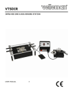
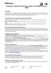
 Home
Theater Fixed Frame Curved Projection Screen
Lunette Series
1 Rev.052611‐AS www.elitescreens.com [email protected] Important Safety & Warning Precautions
Please follow these instructions carefully to ensure proper maintenance and safety with your screen. 1. Please make sure that no other objects such as power switches, outlets, furniture, ladders, windows, etc. occupy the space designated to hang the screen. 2. Regardless if the screen is installed inside or on the wall, make sure that the proper mounting anchors are used and that the weight is supported appropriately by a strong and structurally sound surface just as any large and heavy picture frame should. (Please consult a home improvement specialist for the best advice on installation.) 3. Frame parts are made of high quality velour‐surfaced aluminum and should be handled with care. 4. When not in use, cover the screen with a furniture sheet to protect from dirt, grime, paint or any other impurities. 5. When cleaning, use a damp soft cloth with warm water to remove any marks on the frame or screen surface. 6. Never attempt to use any solutions, chemicals or abrasive cleaners on the screen surface. 7. To avoid damaging the screen, do not touch the material directly with your fingers, tools or any other abrasive or sharp objects. 8. Spare parts should be placed out of reach for small children in accordance with household safety guidelines . Caution: •
The projection screen frame is made of high‐quality aluminum alloy and should be handled with care. •
Use a soft cloth with warm water to remove any spots on the screen surface. •
To avoid damaging the screen material, never attempt to use any solutions, chemicals or abrasive cleaners on the screen, and avoid touching the material with your fingers or sharp/abrasive objects. 2 Rev.052611‐AS www.elitescreens.com [email protected] Parts List for the Lunette Series
Please make sure all parts listed below are included before proceeding with the installation. A. Dry‐wall anchor B. 1.77” L‐Bracket C. 3.54” L‐Bracket D. Y‐Bracket E. M5 Screw F. Wood Screw G. Fix Plate H. Center Support Bar I. Support Joiner J. Elbow Joint K. Butterfly Screw L. Tension Rods M. Vertical Upright Frame N. Horizontal Curved Frame O. Screen Material 3 Rev.052611‐AS www.elitescreens.com [email protected] Installation Instructions
Assembly 1. Insert both Elbow Joints (J) into each Horizontal Curved Frame (N) and join all four frame parts together as shown below. 2. After making sure that all four corners join at right angles to form a perfect rectangle and fasten together with the M5 screws (E). Minimal gap is normal here
3. Lay out the Screen Material (O) and Tension Rods (L) on a clean and dry surface and gently roll out the screen material on the back of the frame. Vertical Upright Frame
Horizontal Curved Frame
Black Backing of the screen material 4 Rev.052611‐AS www.elitescreens.com [email protected] 4. Insert the screen Tension Rods (L) through the sleeves according to their corresponding length on each edge of the screen. 5. Slip the tension rods into the grooves running along each side on the back of the frame. Clip on the Fix Plates (F) to the back of the frame to secure the rods into place forming a tight and flat surface. Tension Rod Fix Plate Viewing Surface 5 Rev.052611‐AS www.elitescreens.com [email protected] Black Backing
g for AccousticP
Pro1080
0 Mode
els This proceedure only ap
pplies to Acou
usticPro 1080
0 models, disrregard if yourr curved frame us now an AcousticP
Pro 1080 variaant. The blackk backing counters the effeects of light p
penetration th
hat would otherwisee light up all ittems behind the screen an
nd spoil the p
picture. The black b
backing goes b
behind the pro
ojection surfacce and is held into position b
by Velcro‐faced
d fix plates. Black backing Fix plate securees AcousticPro10
080 and the backing. A
AcousticPro1080 Screen Material Cover by Blackk backing. Blackk backing Fiix Plate TTension Rod (Stretches the AccousticPro1080 material) After the m
material has be
een installed, the backing will lie over the b
back of the whiite (AcousticPrro1080) materiial and then be heeld into place b
by the fix plates as they’re ad
dded (Fig.1‐3). Interval markin
ngs reveal the suggested points of attachmen
nt (Fig.1). The p
prongs on the ffix plates (Fig.2
2) straddle a lip
p on the back o
of the frame crreating friction
n to hold the m
material in place
e (Fig.3‐4). Fig.1 Fig.2 backing to the back of the AccousticPro1080
0 material is to
o utilize the Vellcro *An alternate way to attaach the black b
tabs locateed on the outer surface of the fix plates (Figg. 3‐4). Fig.3 Fig.4 6 Rev.052611‐A
AS www.elitescrreens.com info@
@elitescreens.com ATTACH THE FIX PLATES 1. Make sure that the material and frame are lying face down on a clean, dry and non‐abrasive surface. 2. Center the material inside the frame. Note: The material will be noticeably smaller because stretching the material is required to create a sufficient amount of tension for perfect material flatness. 3. Start attaching the Fix Plates in the center of the Horizontal Curved Frame’s edge and (1) then alternate with the center short sides (2). Note: Follow these instructions to make sure the material is properly fixed in the center position of the frame. After attaching the Fix Plates in sequence #2 (the center of the short sides), please remove the fix plates in sequence #1 (the center of the long horizontal edge) and reattach them again, and also remove the fix plates on sequence# (2) and reattach them again. 4. Then continue to follow our recommended order numbers 3‐8 to properly distribute tension to the screen material. 7 Rev.052611‐AS www.elitescreens.com [email protected] CENTER SUPPORT BAR 1. Insert the Support Joiner (I) into each side of the Center Support Bar (H) to complete assembly. Support joiner Center support bar 2. Insert the Center Support Bar (H) into the upper top groove on the back of the frame (not the one where the fix plate inserts) with the bottom end near the approximate center point of the frame and place it in at an angle so that both ends of the bar are in alignment with the groove. 3. Slide the top end of the end bar into the top center point location as shown below to complete the center support bar installation. This will provide added stability to your frame and add tension to the material. 8 Rev.052611‐AS www.elitescreens.com [email protected] INSTALLATION Wall
Horizontal Curved Frame Mid‐Point (Y‐Bracket)
L‐Point (L‐Bracket) R‐Point (L‐Bracket)
9 Rev.052611‐AS www.elitescreens.com [email protected] 1. Locate your desired installation height, draw the Datum Line and mark the drill‐hole area of the Mid‐Point. Note: The center of the hole must align with the Datum Line. 2. Mark the drill‐hole area of the L‐Point and the R‐Point. The top of the bracket must align with the Datum Line. 3. Drill a hole with the proper bit size according to the included Wood Screws (F). 4. Line up the brackets with the drilled holes on the installation location and screw then in using a Phillips screwdriver. 5. Position the fixed frame screen onto the Y‐Bracket (D) and push down at the center of the bottom frame to secure the insertion of the frame into the Y‐Bracket. 6. Combine the 1.77” L‐Bracket (B) with the installed mounted 3.54” L‐Bracket (C) using the Butterfly Screws (K) and then position frame onto the bracket. Note: Step 6 only refers to models 125w and above. Models 85w‐115w use four 1.77” L‐Brackets (B). 7. The brackets provide flexibility by allowing the fixed frame screen to slide to the slides. This is an important feature as it allows your screen to be properly centered. 10 Rev.052611‐AS www.elitescreens.com [email protected] Model Numbers Parts List Curve235 Model Number 85w 96w 103w 115w 125w 138w 147w 158w 2
2
4
9
1
2
2
1
2
44
7
7
4
0
1
5
2
2
4
9
1
2
2
1
2
52
7
7
4
0
1
5
2
2
4
9
1
2
2
1
2
52
7
7
4
0
1
5
2
2
4
9
1
2
2
1
2
56
7
7
4
0
1
5
2
2
4
9
1
2
2
2
4
62
9
9
2
2
1
5
2 2 4 9 1 2 2 2 4 66 9 9 2 2 1 5 2
2
4
9
1
2
2
2
4
68
9
9
2
2
1
5
2
2
4
9
1
2
2
2
4
72
9
9
2
2
1
5
Part Name Horizontal Curved Frame Upright Vertical Frame Elbow Joint M5*15 Assembly Screw Screen Material Top/Bottom Tension Rod Side Tension Rod Center Support Bar Support Joiner Fix Plate Dry‐wall anchor M5*45 Wood Screw 1.77" L‐Bracket 3.54" L‐Bracket Y‐Bracket Butterfly Screw Dimensions of Diagram on page 9
Model Number 85w 96w 103w 115w 125w 138w 147w 158w View Width (A1) 78.19” (1986) 88.35” (2244) 94.77” (2407) 105.83” (2688) 115.00” (2921) 126.97” (3225) 135.24” (3435) 145.40” (3693) View Height (A2) 33.28” (845) 37.56” (954) 40.31” (1024) 45.00” (1143) 48.90” (1242) 53.98” (1371) 57.52” (1461) 61.81” (1570) Overall Width (B1) 85.28” (2166) 95.43” (2424) 101.85” (2587) 112.90” (2868) 122.09” (3101) 134.06” (3405) 142.32” (3615) 152.48” (3873) Overall Height (B2) 40.35” (1025) 44.65” (1134) 47.40” (1204) 52.09” (1323) 55.98” (1422) 61.06” (1511) 64.6” (1641) 68.90” (1750) Frame Height (C) 3.39” (86) 3.86” (98) 4.17” (106) 4.80” (122) 5.35” (136) 6.22” (158) 6.81” (173) 7.56” (192) Distance (D) Distance (E) 39.96” (1050) 45.28” (1150) 47.24” (1200) 51.18” (1300) 59.06” (1500) 62.99” (1600) 66.93” (1700) 68.90” (1750) 39.96” (1050) 45.28” (1150) 47.24” (1200) 51.18” (1300) 59.06” (1500) 62.99” (1600) 66.93” (1700) 68.90” (1750) Measurement dimensions are intended as a reference only and subject to change without notice. Note: Data Error may be ±1" Unit: (mm) 11 Rev.052611‐AS www.elitescreens.com [email protected] Lunette
L
Series Dimenssion Taable1
Unit:mm
Model
Curve235-85
5W
Curve235-96
6W
Curve235-103
3W
Curve235-115
5W
Curve235-125
5W
Curve235-138
8W
Curve235-158
8W
Unit: Inches
Model
Curve235-85
5W
Curve235-96
6W
Curve235-103
3W
Curve235-115
5W
Curve235-125
5W
Curve235-138
8W
Curve235-158
8W
Diago
onal
Size/As
spect
Ratio
85"(2.3
35:1)
96"(2.3
35:1)
103"(2..35:1)
115"(2..35:1)
125"(2..35:1)
138"(2..35:1)
158"(2..35:1)
Overrall
Widtth
(A))
216
66
242
23
258
87
286
67
310
01
340
05
387
72
Viewing
Width
(A1)
1986
2243
2407
2687
2921
3225
3692
Frame
Width
(A2)
90
90
90
90
90
90
90
Overall
O
H
Height
(B)
1025
1134
1204
1323
1423
1552
1751
View
wing
Heig
ght
(B1)
84
45
95
54
102
24
114
43
124
43
137
72
157
71
Diago
onal
Size/As
spect
Ratio
85"(2.3
35:1)
96"(2.3
35:1)
103"(2..35:1)
115"(2..35:1)
125"(2..35:1)
138"(2..35:1)
158"(2..35:1)
Overrall
Widtth
(A))
85.3
3
95.4
4
101.9
112.9
122.1
134.1
152.4
Viewing
Width
(A1)
78.2
88.3
94.8
105.8
115.0
127.0
145.4
Frame
Width
(A2)
3.5
3.5
3.5
3.5
3.5
3.5
3.5
Overall
O
H
Height
(B)
40.4
44.6
47.4
52.1
56.0
61.1
68.9
View
wing
Heig
ght
(B1)
33.3
37.6
40.3
45.0
48.9
54.0
61.9
B2
C
90
90
90
90
90
90
90
86
98
106
122
136
158
192
B2
C
3.5
3.5
3.5
3.5
3.5
3.5
3.5
3.4
3.9
4.2
4.8
5.4
6.2
7.6
Frame
Depth
(D)
40
40
40
40
40
40
40
Frame
Depth
(D)
1.6
1.6
1.6
1.6
1.6
1.6
1.6
E
1050
1150
1200
1300
1500
1600
1750
E
41.3
45.3
47.2
51.2
59.1
63.0
68.9
Measurem
ments are intend
ded as a referen
nce only and are subject to change without noticce. Note: Data EError may be ±1"" Unit: mm 12 Rev.052611‐A
AS www.elitescrreens.com info@
@elitescreens.com Warranty Policy
•
•
•
•
•
•
•
•
Two (2) Year parts and labor warranty from defects in workmanship from purchase date as follows (except for refurbished units as specified below). Three (3) Year parts and labor warranty from defects in workmanship for GEMR (Government, Educational, Military, & Religious) purchases of new product only. Refurbished Units carry a 90‐DAY parts and labor warranty. Each party will be responsible for one way shipping during the warranty period. A RMA (Return Merchandise Authorization) number must be issued in order to process a replacement or to authorize a return for warranty repair. Elite Screens will, at its sole option replace or repair the defective unit with a replacement *(see exceptions below) after the defective unit or parts have been received. Once the product is received, Elite Screens will send out a replacement *unit to the customer by ground service (subject to inventory availability). Do Not Return Any Unauthorized Items to Elite Screens, as they will be refused and returned at your expense. The RMA Number must be included on the outside label of your shipping box. Our warehouse is not authorized to accept returns without an RMA number on the shipping label. RMA Numbers are valid for 45 days from the date issued. Missing Parts must be reported within 7 days of receipt. If reported after 7 days, the customer will be responsible for shipping and handling fees. If reported after 30 days of receipt, the customer will be responsible for cost of parts and shipping & handling fees. *A New or refurbished replacement will be send out to the customer depending on the type of purchase (new or refurbished) and based on stock availability. North America only U.S. and Canada For Warranty and Service requests, please submit an RMA/Service Form at: www.elitescreens.com/warrantysupportform Please visit this link for full Warranty information: www.elitescreens.com/warranty For Customer Service and Technical questions, please contact Elite Screens at: Telephone: (877) 511‐1211 [email protected] Fax: (562) 926‐8433 [email protected] REMEMBER TO REGISTER YOUR PRODUCT AT: www.elitescreens.com 13 Rev.052611‐AS www.elitescreens.com [email protected] Contact Info
US & Canada Tech Support & Warranty Claim Please contact us at [email protected] or call +1 877‐511‐1211 #3 or fax +1‐562‐926‐8433 Europe Tech Support & Warranty Claim Please contact us at [email protected] or call +49‐(0) 40‐30392958 Asia Tech Support & Warranty Claim Please contact us at [email protected] or call +86‐(0) 755‐8461‐7989 Taiwan Tech Support & Warranty Claim Please contact us at [email protected] or call +866+2+8990‐1999 America: Elite Screens Inc 16410 Manning Way Cerritos, CA 90703 USA Tel: +1‐877‐511‐1211 Fax: +1‐562‐926‐8433 [email protected] www.elitescreens.com Asia: Elite Screens China Corp. Longxi Duimianling Industry Zone Longcheng Longgang District, ShenZhen GuangDong, China Tel: +86‐(0)755‐8461‐7989 Fax: +86‐(0)755‐8461‐7669 [email protected] www.elitescreens.com.cn Taiwan: Elite Screens Taiwan Corp. 4F., No. 42‐1 Wuguan Rd. Wugu Township Taipei County 248, Taiwan (Wugu Industrial Park) Taiwan (R.O.C) Tel: +886+2+8990‐1999 Fax: +886+2+8990+1366 [email protected] www.elitscreens.com.tw Europe: Elite Screens Europe Lübecker Straße 1 22087 Hamburg, Germany Tel: +49‐4030392494 Fax: +49‐40‐49219200 [email protected] www.elitescreens.eu Elite Screens France S.A.S 11, Allée William Penn 92150 Surenes, France Tel: +33‐1‐45064735 Fax: +33‐1‐45064735 [email protected] www.elitescreens.com/fr Japan: Elite Screens Japan Corp. 467‐2‐606 Tsuruma, Machida‐shi, Tokyo, 194‐0004 Japan Tel: 0120‐07‐0008 Fax: + 81(0)42‐706‐9130 [email protected] www.elitescreens.jp Latin America Contact: [email protected] East Asia Contact: [email protected] India Contact: [email protected] 14 Rev.052611‐AS www.elitescreens.com [email protected]