1
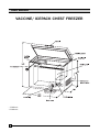
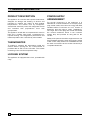
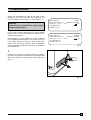
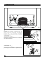
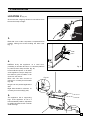
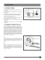
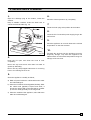
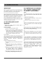
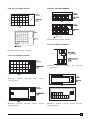
USER s MANU AL FCW 200 FCW 300 VACCINE/ ICEPACK CHEST FREEZER GB F E 1291110 820 41 70 04 USER MANUAL VACCINE/ ICEPACK CHEST FREEZER * FCW 200 ** FCW 300 2 INDEX 1. 2. 3. 4. 5. 6. GENERAL INFORMATION ..................................................................................................page INSTALLATION ....................................................................................................................page HOW TO USE.......................................................................................................................page DEFROSTING & CLEANING...............................................................................................page PERIODIC OBSERVATIONS/CHECKS/ACTIONS............................................................page TROUBLE SHOOTING ........................................................................................................page (A) The appliance is not working (B) Compressor is working, but cabinet temperature is higher than normal (C) Abnormal noise in the appliance 7. SHUTTING DOWN...............................................................................................................page 8. STORAGE OF VACCINES AND ICEPACKS IN THE APPLIANCE ...................................page 4 5-8 8-10 10-11 12 13-14 14 14 3 1. GENERAL INFORMATION PRODUCT DESCRIPTION The appliance is a vaccine and icepack chest freezer designed for storage and freezing of vaccine and icepacks for medical use mainly at high ambient temperatures. The freezer runs by compressor 230V/50Hz electrical power with refrigerant R134a and insulated with polyurethane foam with cyclopentane. The appliance is built with a compartment for vaccine load and a smaller fast freeze compartment for icepack freezing. The refrigerators performance and inside temperature are controlled by a thermostat. THERMOMETER To enable to measure the temperature inside the cabinet without opening the lid, a thermometer is provided with its dial on the front side. This makes monitoring of the vaccine temperature easy. LOCKING SYSTEM The appliance is equipped with a lock, operated with a key. 4 POWER-SUPPLY ARRANGEMENT For smooth functioning of the appliance it is advisable to connect the same to a 15 Amps power plug socket outlet, wired from the mains with PVC insulated cables of minimum 2.5 mm2 section of Aluminium (see also page 2 under `Installation'). The larger size of the plug and socket decreases the contact resistance which in turn reduces voltage drop and provides an easy path for the current. Safety of the personnel and the equipments can not be guaranteed unless the earth wire (green/yellow) of the cord is really earthed. It is advisable to have the earth connections to the socket checked by a competent electrician. 2. INSTALLATION Check the manufacturer's plate at the back of the appliance and make sure that the appliance has correct voltage for local supply, i.e. 230 volt (fig. 1 ). CAUTION: Connecting the equipment to wrong supply voltage may damage it. If you have received equipments of wrong voltage ratings, notify concerned authorities and keep the equipments repacked. The appliance is to be installed in a well ventilated room, avoiding direct sunshine or any other source of heat. Power supply socket (15 amps socket with switch, fuse and mains indicator lamp is advisable) should be available nearest to the place of installation of the appliance. MOD. FCW 200 CLASS T PROD. NO 9206651-01 SERIE NO 12345678 230-240 V ~ 50 Hz 110W 13A VOL: GROSS 193 L R 134a 0,120 kg MOD. FCW 300 CLASS T PROD. NO 9206031-01 SERIE NO 12345678 230-240 V ~ 50 Hz 140W 13A VOL: GROSS 335 L R 134a 0,156 kg Fig 1. 1. Unscrew and remove the screws holding the plastic grid of the compressor compartment on the right hand side of the appliance and remove carefully the grid (fig. 2) Fig 2. 5 2. INSTALLATION Fig 3. 2. EXAMINE the compressor compartment (fig. 3). Check carefully for any damage, dislocation or looseness etc. of the components, specially at locations A, B and C as below and rectify if necessary. LOCATION A (fig. 4) Check that all 4 mounting brackets of the compressor are in place and secured. Fig 4. LOCATION B (fig 5) Check that the incoming electrical connections of the power supply cord to the terminal strip are tight. Fig 5. 6 2. INSTALLATION LOCATION C (fig. 6) Check that the outgoing electrical connections from the terminal strip are tight. 3. Fig 6. Refit side cover of the compressor compartment into position refixing the screws holding the side cover (fig. 7) 4. INSTALL firmly the appliance on a level floor, preferably on wooden blocks or on a wooden platform to protect it from damp and dirt. (fig. 8) Leave sufficient space on all sides of the appliance, keep it away from the walls for good circulation of air around it, see below: Back and left side should be minimum 3 cm away from the walls (fig. 8a) Fig 7. Fig 8a. Hinges can be pushed against the wall. Right side should be minimum 10 cm away from the wall (fig. 8b) 5. The appliance has 4 supporting legs. If the appliance is not in a level and stable position, adjust this by adding wooden blocks or similar under the legs. Fig 8. Fig 8b. 7 2. INSTALLATION 6. Connect the leads of the power supply cord to a suitable 3-pin plug as shown below (fig. 9) Lead of cord Green/yellow Blue Brown Pin of plug Earth Neutral Phase NOW THE APPLIANCE IS READY TO START Fig 9. 3. HOW TO USE 1. Install and prepare the appliance as detailed under `Installation' in the previous chapter. 2.TEMPERATURE CONTROL The thermostat ensures that the required temperature is maintained in the freezer. Adjust the temperature by turning the button with a coin that fits the groove. Turning the thermostat button towards no. 7 makes the temperature in the freezer colder, and turning the button towards no. 1 makes the temperature warmer. The inner temperature must not be lower than -15 °C. Fig 10. 8 3. HOW TO USE 3. CONTROL PANEL The green light is illuminated as long as the freezer is connected. Thermostat button Yellow light Red alarm light Green light The yellow light is illuminated when the Super button is depressed. The red light is illuminated when the temperature in the freezer is higher than the thermostat setting. The red alarm light can be due to: Insertion of a large amount of vaccine/icepack. The red alarm light will go out after a while. SUPER button Fig 11. Opening the lid too long. The red alarm light will go out after a while. A defect in the system. See under TROUBLE SHOOTING 4. OPENING/CLOSING THE LID The lid is fitted with a tightly closing sealing strip to prevent moisture getting inside the freezer and increasing the amount of frost formed. When the lid is opened the air inside the freezer becomes slightly warmer and expands. As soon as the lid is closed again the air is cooled immediately. This may lead to the creation of a vacuum which makes it hard to open the lid immediately after it has been closed. This is quite normal. Wait a few minutes until the vacuum has disappeared, then open the lid by pulling gently. Never pull the handle violently. 5. Allow the appliance to run. The temperature inside the cabinet will be indicated on the thermometer on the front side. Observe the temperature from time to time (fig.12) 6. Initially the temperature inside the appliance will be similar to, or slightly below, the room temperature. It should decrease slowly and should remain steady within a small range, after 1-3 days, depending upon different conditions. Fig 12. 9 3. HOW TO USE 7. If the cabinet temperature does not reach the required low level of 2-3 days, the freezer-thermostat setting can be increased to a higher setting by turning its knob clockwise. 8. After storing the vaccines, keep the lid properly closed and locked (fig. 13). 4. DEFROSTING & CLEANING DEFROSTING & CLEANING The moisture in the air, which enters the appliance due to lid opening (and also may be due to defective lid-gasket or door alignment) is attracted by the cold surfaces inside the appliance. So, formation of frost and ice occurs on the walls. When the frost layer is 1 /4" to 1 /2" (6-12 mm) thick, it is time for `defrosting' the appliance. MOST IMPORTANT: Before defrosting the appliance, the vaccines preserved in it will have to be removed and stored temporarily in other working freezer. If a second appliance is not available, the vaccines will have to be preserved in Cold-Box or Vaccine carrier, properly lining the same with frozen ice packs, such that the vaccine temperature remains within the recommended storage temperature during the defrosting of the appliance. DEFROSTING & CLEANING PROCEDURE 1. Switch OFF the power supply to the appliance and remove the plug of its power supply cord from the wall socket. 2. Prepare the temporary storage and transfer the vaccines and preserve them properly with care. 10 Fig 13. 4. DEFROSTING & CLEANING 3. Open the drainage plug at the bottom, inside the cabinet. Keep a suitable container under the drain hose to collect the defrost water (fig. 14). 6. Allow the cleaned parts to dry completely. 7. Reset the drain plug at its position at the bottom. 8. Close the lid. Connect the power supply plug to the wall socket. 9. Allow the appliance to run and observe the cabinet temperature on the thermometer. 10. Fig 14. 4. Put back the vaccines into the appliance from the temporary storage, only when the appliance has attained safe recommended temperature range for storage of the vaccines. Keep the lid open and allow the frost to melt completely. Never use any heat source other than hot water to speed up defrosting. Never use any sharp-edged instrument for removing frost or for cleaning the liner etc. 5. Clean the appliance carefully as below, a) Wash all parts inside the cabinet with warm water and mild detergent. b) Clean the lid and the lid seal (gasket) similarly. After the rubber seal (gasket) is wiped and dried, it should be rubbed with unscented talcum powder (or French chalk) specially on the hinge side. c) Clean the outside of the appliance, also with warm water and mild detergent. 11 5. PERIODIC OBSERVATIONS / CHECKS / ACTIONS DAILY 1. Take temperature readings from the thermometers and note down the temperature and the time of reading. Keep the temperature records systematically. It is suggested that minimum 2 readings should be taken (in the morning and afternoon) preferably at the same hours of each day. If the temperature is observed to be below or above the required range, adjust the thermostat (see Action 2 on page 8) by steps, allow the appliance to run for about one hour under observation. If required, adjust the thermostat further until the required temperature range is obtained. To make the inside colder, the thermostat knob is to be turned clockwise to a higher setting. To make the inside warmer, the thermostat knob is to be turned anti-clockwise to a lower setting. 2. Clean the exterior of the appliance with a clean dry cloth. WEEKLY 1. Examine the inner compartment and see if frost formation is more than 1 /4" (6 mm). If so, DEFROST the appliance as described earlier (see page 10). If it is observed that Defrosting is required to be done each week: a) Examine the rubber seal on the lid, if it sits properly. Any gap between the cabinet and seal can be checked by placing a visiting card between them. The card should resist being pulled out freely. If the card can be pulled out freely, there exists a gap. Such gap will allow outside air to go in and form frost early. In such cases the lid should be adjusted or the seal should be changed. b) Restrict and reduce frequency of opening the appliance. Open only when absolutely necessary. MONTHLY 1. Clean the compressor compartment: a) Put off the switch, if any, and take out the plug from the wall socket. 12 b) Take out the plastic grid of the compressor compartment (see page 5, actions 1 ). Clean the interior of the compressor compartment with a soft brush. c) Check the mounting brackets of compressor, if they are tight. If not, rectify. d) Fit back the plastic grid (see page 7, actions 3) 2. Clean the lid seal (see page 11, action 5b). 3. If possible, put a standard mercury thermometer inside the cabinet and compare the readings with those of the dial thermometers and see if they are correct. Dial thermometers with incorrect readings may have to be re-adjusted or replaced, as incorrect readings may lead to wrong storage temperature and loss of the potency of the vaccines preserved. 6. TROUBLE SHOOTING IMPORTANT: When an appliance is found to be not working at all or not working properly, see that the vaccine temperature is within the recommended limits. Do not open the lid unless very essential. Observe temperature from time to time and if you feel that temperature may exceed the higher limit before the appliance is repaired - transfer the vaccines to other working appliance/refrigerator or cold-box. B) COMPRESSOR IS WORKING, BUT CABINET TEMPERATURE IS HIGHER THAN NORMAL NOTE: The cabinet temperature may go little higher than normal, but should come down after some time when: New vaccines are stored The lid is opened frequently or kept open for longer duration For any abnormal sound, smoke, smell etc. in the appliance disconnect the plug from the wall socket and notify refrigerator technician. A) THE APPLIANCE IS NOT WORKING 1. Observe the green mains-on indicator light on right on the front panel. IF NOT GLOWING I) Check if wall socket switch is OFF II) Check if power supply is available at the wall socket. This can be tested by connecting an electric lamp or other appliances to the socket. The lamp should glow or the appliances should work, if supply is available at the socket. If not available: There may be some defect in the power supply circuit (viz: blow-off fuse, loose connections, faulty switch or socket, single phasing etc.) which should be rectified through competent Electrical Maintenance Technicians. If power is available at the socket: III) Check that the plug is inserted properly into the socket. IV) Check the plug for loose connection or dislocation of power supply cable connections rectify if required. V) Remove the plug from socket. Check the incoming and outgoing cable connections on the terminal strip in the compressor compartment (see page 6, actions 2B and 2C) Unfrozen ice packs are put in for freezing. 1. Check if recommended space is left on back and sides of the appliance for air circulation (see page 7, action 4). 2. Check if there is too much frost formation in the liner chamber on the inside walls. If so, defrost (see page 10 for Defrosting and Cleaning) 3. Check if the compressor is cut off by the thermostat before required temperature is attained. If so, adjust thermostat setting (see page 8, action 2). 4. If the compressor is observed to be running continuously but no cooling is attained - this may be due to leakage of refrigerant gas from the system or defect in the unit, - Notify Refrigerator Technician. 5. Check if the compressor tries to start but trips-off early by the over-load protector. This may be either due to too low supply voltage or defect in the compressor or starting relay - put `off' the appliance till return of normal voltage and try to run once again. If the defect prevails, - Notify Refrigerator Technician. VI) Even after actions as above, the green lamp is not glowing - Notify Refrigerator Technician. 13 6. TROUBLE SHOOTING C) ABNORMAL NOISE IN THE APPLIANCE 3. Check if any pipe or component has come out of its position and also touching others. !f so, rectify carefully. In case of any abnormal noise coming out from the appliance, try to locate the source of the noise. Generally it may come from the compressor compartment. In such cases, 4. Check if the appliance is level and firm on its base. If not, rectify. 1. Take out the plug of the appliance from socket and open the plastic grid of the compressor compartment (see page 5, actions 1 ) 5. Even after actions as above if it is observed that the noise is still present or it is coming from the inside of the compressor - Notify Refrigerator Technician. 2. Examine if the mounting brackets of the compressor are in place and secure, and if the mounting bolts for the fan are tight. If required replace broken or lost brackets and tighten loose bolts (see page 6 & 7, fig. 4 & 6) 7. SHUTTING DOWN IF THE APPLIANCE IS TO BE SHUT DOWN FOR TRANSPORTATION ETC. Disconnect the power-supply plug from socket Defrost and clean the interior Leave the lid open till the appliance is absolutely dry Roll the power supply cord into a coil and bind and place it carefully to avoid damage 8. STORAGE OF VACCINE AND ICEPACKS IN APPLIANCE FOR STORING VACCINES 1. Keep the packets containing the vaccines in neat rows, 2. Different vaccines should be kept separately to facilitate easy identification. 3. Keep about 2 cm space between rows for circulation of air. 4. Keep a separate thermometer among the vaccines to ascertain the actual vaccine temperature. 14 FCW 200 VACCINE LOADING FCW 300 VACCINE LOADING Vaccine storage capacity 264 litre FCW 300 ICEPACK LOADING Vaccine storage capacity 144 litre FCW 200 ICEPACK LOADING Maximum icepack 7,2 kg/24hour Maximum icepack 7,2 kg/24hour Maximum icepack 13,2 kg/24hour freezing freezing with without freezing with vaccine vaccine vaccine Maximum icepack freezing without vaccine 22,8 kg/24hour 15 Printed by Xerox Hungary Ltd. 2003. 02. 12<None>.