1
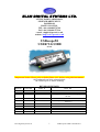
ELAN DIGITAL SYSTEMS LTD.
LITTLE PARK FARM ROAD,
SEGENSWORTH WEST,
FAREHAM,
HANTS. PO15 5SJ.
TEL: (44) (0)1489 579799
FAX: (44) (0)1489 577516
e-mail: [email protected]
website: http://www.pccard.co.uk
USBscope50
USER’S GUIDE
ES370
Important Notice: Please refer to Safety Data 4.4.1, before using this instrument
All Trademarks are duly acknowledged.
The USBscope50 is Patent Pending.
REVISION HISTORY
ISSUE
PAGES
DATE
NOTES
1
2
3
30
30
31
04.07.2005
08.07.2005
15.07.2005
4
5
31
39
20.07.2005
27.09.2005
FIRST ISSUE
Various additional info & spec amendments
Add support for Win98 & DBCS Language’s in
2K/XP
Various additional info & amendments
General update. Explain trigger modes, Math,
FFTs etc
Elan Digital Systems Ltd.
1
USBscope50 USER’S GUIDE Iss5
CONTENTS
1
OVERVIEW................................................................................................ 5
2
ABOUT THE USBSCOPE50 ..................................................................... 6
2.1
General ............................................................................................................ 6
2.2
USBscope50 Architecture .............................................................................. 7
2.3 Using More Than One USBscope50.............................................................. 8
2.3.1 Assembling The Stack ............................................................................... 8
2.3.2 Disassembling The Stack......................................................................... 10
2.3.3 USB Connections For Stacked Configurations........................................ 11
2.3.4 Software For Stacked Configurations...................................................... 11
2.3.5 Stacking Do’s And Don’ts ....................................................................... 13
2.4
Input Ranges ................................................................................................. 14
2.5
Probe Compensation .................................................................................... 15
2.6 Acquisition Modes ........................................................................................ 18
2.6.1 Single Shot ............................................................................................... 18
2.6.2 Random Interleaved Sampling................................................................. 19
2.7 Trigger Modes............................................................................................... 21
2.7.1 Auto Triggering ....................................................................................... 21
2.7.2 Normal Triggering ................................................................................... 22
2.7.3 Free Triggering ........................................................................................ 22
2.8
Trigger Position ............................................................................................ 23
2.9
Trigger Delay ................................................................................................ 23
2.10
Trigger Threshold ..................................................................................... 25
2.11
Full Screen Plot.......................................................................................... 25
2.12
FFT Plot (Spectrum Analyser)................................................................. 27
2.13
Math Functions.......................................................................................... 28
2.14
Data Export................................................................................................ 29
2.14.1
Example Data File ................................................................................ 30
2.14.2
Example FFT File................................................................................. 31
3
SOFTWARE INSTALLATION ................................................................. 32
3.1
Windows 98SE and Windows Me ............................................................... 32
3.2
Windows 2K and XP .................................................................................... 34
Elan Digital Systems Ltd.
2
USBscope50 USER’S GUIDE Iss5
4
HARDWARE SPECIFICATION ............................................................... 36
4.1
Power Requirements .................................................................................... 36
4.2
Mechanical .................................................................................................... 36
4.3
Environmental .............................................................................................. 36
4.4 Performance .................................................................................................. 37
4.4.1 Safety Data and Maximum Ratings ......................................................... 37
4.4.2 Static Performance ................................................................................... 38
4.4.3 Dynamic Performance ............................................................................. 39
4.4.4 Miscelaneous............................................................................................ 39
Elan Digital Systems Ltd.
3
USBscope50 USER’S GUIDE Iss5
Disclaimer
This document has been carefully prepared and checked. No responsibility can be
assumed for inaccuracies. Elan reserves the right to make changes without prior notice
to any products herein to improve functionality, reliability or other design aspects. Elan
does not assume any liability for loses arising out of the use of any product described
herein; neither does its use convey any license under its patent rights or the rights of
others. Elan does not guarantee the compatibility or fitness for purpose of any product
listed herein. Elan products are not authorized for use as components in life support
services or systems. Elan should be informed of any such intended use to determine
suitability of the products.
Software supplied with Elan PC-Cards, Compact Flash cards or USB devices is
provided “as-is” with no warranty, express or implied, as to its quality or fitness for a
particular purpose. Elan assumes no liability for any direct or indirect losses arising
from use of the supplied code.
Copyright © 2005 Elan Digital Systems Ltd.
Federal Communications Commission (FCC) Statement
This equipment has been tested and found to comply with the limits for a Class A digital device,
pursuant to Part 15 of the FCC Rules. These limits are designed to provide reasonable protection
against harmful interference in a residential installation. This equipment generates, uses, and can
radiate radio frequency energy and, if not installed and used in accordance with the instructions, may
cause harmful interference to radio communications. However, there is no guarantee that interference
will not occur in a particular installation. If this equipment does cause harmful interference to radio or
television reception, which can be determined by turning the equipment off and on, the user is
encouraged to try to correct the interference by one or more of the following measures:
- Reorient or relocate the receiving antenna
- Increase the separation between the equipment and receiver
- Connect the equipment into an outlet on a circuit different from that to which the receiver is
connected.
- Consult an Elan authorized dealer or service representative for help.
Elan is not responsible for any radio or television interference caused by using other than
recommended cables and connectors or by unauthorized changes or modifications to this equipment.
Unauthorized changes or modifications could void the user's authority to operate the equipment.
This device complies with Part 15 of the FCC Rules. Operation is subject to the following two
conditions (1) this device may not cause harmful interference, and (2) this device must accept any
interference received, including interference that may cause undesired operation.
Listed Products
The models covered by this installation guide are intended only for installation in Listed computers for
use in business or home.
Elan Digital Systems Ltd.
4
USBscope50 USER’S GUIDE Iss5
1 OVERVIEW
The USBscope50 is a digital storage oscilloscope that has the
following features:
• Single channel scope with BNC input and USB PC interface
• Each USBscope50 can be stacked to increase channel count (each
requires its own USB connection)1
• 300V Cat II isolation between BNC ground and USB ground2
• 50MSample/sec single shot sample rate
• 1GSample/sec equivalent sample rate3
• Timebase from 4ns/div to 4s/div in 1,2,4 steps
• 75MHz 3dB analogue bandwidth4
• 3000 sample points, 8-bits per sample
• Pre and post triggering, and trigger delay5
• AC and DC coupling
• Input sensitivities with x1 probe are 30mV/div, 300mV/div,
3V/div and with x10 probe are 300mV/div, 3V/div, 30V/div
• 1Meg input impedance, 16pF
• Channel offset control
• Auto and Normal hardware triggering with >, <, +, – modes
• Host powered from USB (200mA typ)
• Stacked configurations of 2,3 and 4 channels are supported
• Stacked configurations allow any channel to be trigger channel
• Stacked configurations have tight phase locking between channels
• Probe compensation output, 3V 1KHz
• Power/activity LED
1
A stacking connector kit is required
In stacked configurations the channels share a common ground at the BNC terminals
3
Suitable to measure repetitive signals that are not phase locked with the internal acquisition clock
4
Hardware trigger bandwidth is approximately 60MHz
5
Only in single-shot mode
2
Elan Digital Systems Ltd.
5
USBscope50 USER’S GUIDE Iss5
2 ABOUT THE USBscope50
2.1 General
The USBscope50 uses a 50MSample/sec 8-bit A-to-D converter.
The A-to-D and front-end circuits that process the input waveform,
and the digital stages that acquire and store the waveform are all
powered from the USB host interface via an isolated supply. This
means that there is no galvanic connection between the BNC ground
(or BNC centre terminal), and the USB interface. When you
measure a circuit and connect the scope ground clip to a voltage that
is not at the same ground potential as the host computer, no current
can flow and the host computer is therefore not forced to be at the
same potential as the circuit under test. This clearly has major safety
advantages. The USBscope50 has been designed so that up to 300V
CAT II6, or 500V CAT I can exist between the scope ground clip
and the host computer ground.
Each USBscope50 can be used as an independent single channel
scope but to enhance flexibility several USBscope50s can be stacked
together to make a combined 2,3 or 4-channel device. In this case,
each scope is synchronised with the others so that the compound
device acts like a single multi-channel instrument.
Each
USBscope50 still needs its own USB connection and the combined
device shares a common ground between all the BNC connectors i.e.
the channels are isolated from the USB but not from each other.
6
The CAT rating refers to how large a transient over-voltage may be when connected to the circuit in
question. The USBscope50 is designed to handle a certain transient over-voltage between the BNC
and the USB host i.e. across the internal isolation circuits. The CAT II UL rating defines a more
severe environment than CAT I and hence larger transients are possible. This is why the isolation
rating for CAT II is lower than the rating for CAT I. For further information on CAT ratings please
refer to www.fluke.com
Elan Digital Systems Ltd.
6
USBscope50 USER’S GUIDE Iss5
2.2 USBscope50 Architecture
The figure below shows a simplified diagram of the USBscope50.
STACK
CONN
AC/DC
CONTROLLER
BNC
COMP
USB
CONTROLLER
Trigger
DATA
ATTENUATOR
1Meg
8-BIT ADC
AMP
PSU
ISOLATION BARRIER
Figure 2.2-1 USBscope50 Architecture Diagram
Elan Digital Systems Ltd.
7
USBscope50 USER’S GUIDE Iss5
USB
2.3 Using More Than One USBscope50
A unique feature of the USBscope50 architecture is that up to 4
devices7 can be stacked to make a multi-channel instrument.
In order to use a stacked configuration, you must purchase the
stacking connector kit. This kit comprises 3 long lead connectors
and 1 short lead connector as shown:
2.3.1 Assembling The Stack
To stack the USBscope50 devices, first be sure that none of them are
connected to a USB port.
Before you begin, put the short lead connector to one-side…you’ll
use that one last.
Now, insert one of the long connectors from the top of one of the
scopes (it doesn’t really matter which one). Push the pins of the
connector into the top of the stacking connector from the side where
you can see the top of the black connector down inside the scope.
Be careful when doing this, don’t use too much force or you may
damage the connector pins. Push the long connector all the way in
until it seats down on the scope’s internal connector. You should be
able to see the gold pins about 2-3mm beyond the bottom surface of
the scope. The connectors have no pin orientation…they can go in 2
possible ways round…both are OK.
7
Don’t stack more than 4, the software will reject this.
Elan Digital Systems Ltd.
8
USBscope50 USER’S GUIDE Iss5
Repeat this for all except the last scope to be stacked.
For the last scope in the stack, do the same as above but use the short
length connector. This time, the pins are shorter so they stop well
inside the scope’s case. This scope MUST be the bottom scope in
the stack. The reason for this is that if you use the long connector,
the pins could be shorted out accidentally, or you may touch the pins
when the scope is connected to a high voltage and you could get an
electric shock! Similarly, if you plan to use only one scope, make
sure there is no stack connector fitted or the shorter connector type is
fitted.
This is a safety critical point so please note it carefully.
Now you can assemble the stack.
Elan Digital Systems Ltd.
9
USBscope50 USER’S GUIDE Iss5
Start with the bottom scope. Hold it in one hand, and put the next
scope on top of the 1st, the same way around. Align the stacking
connectors and when the stacking connectors are partly mated
engage the front “P” shaped clip (BNC end) on the 2nd scope into the
“P” shaped slot on the 1st scope.
Now, bring the back edge “P” clip (USB end) of the 2nd scope down
until it clicks into the 1st scope’s slot. These two scopes are now
mated.
Check that as you pushed the 2nd scope down, the stack connector
has not been forced upward…if it has simply press it down until it
seats correctly (see picture above for a guide as to the normal
exposed connector depth after stacking). Repeat this for each
remaining scope, adding each one on top of the previous one.
The scopes are now stacked.
2.3.2 Disassembling The Stack
Start with the top scope in the stack. Grasp the stack in one hand
and with the other hand’s thumb and forefinger, pinch between the
interface between the top two scopes, near the back “P” clip (USB
end). With moderate force, the top scope will pop up and come free.
Remove the stacking connector from the free scope.
Repeat this for all scopes in the stack.
Elan Digital Systems Ltd.
10
USBscope50 USER’S GUIDE Iss5
2.3.3 USB Connections For Stacked Configurations
All stacked scopes need a USB connection. A standard hub may
be useful for multi-channel stacks to get enough USB ports.
Each scope needs about 200mA. Plugging more than 2 scopes into a
hub will mean that the hub may need to be powered externally.
Please refer to the hub’s documentation for more details about the
power available per port.
2.3.4 Software For Stacked Configurations
When you run USBscope50, it will automatically detect the scopes
connected via USB and will also check to see if the scopes are
electrically connected together via the stack. It will then initialise all
connected scopes, one at a time. This may take a few seconds.
If you stack several scopes but forget to connect say one of the
scopes to a USB port, the software will warn you and will not run.
The software will display a channel “tab” for each scope in use.
The channel number allocated to each scope depends on its serial
number, so the order you stacked them will almost certainly NOT be
the same as the channel order allocated by software.
To find out which scope is Channel 1, use the CH1 tab and click the
“id” button.
The LED on that scope will blink rapidly for about 4 seconds, or
until you click the button again.
Elan Digital Systems Ltd.
11
USBscope50 USER’S GUIDE Iss5
Repeat this for each channel in the stack to identify them.
If you like, you can stop the software, and unplug all the scopes from
their USB connections, and then re-stack them in their channel order.
The “about” tab lists all the scopes that have been found. Click on
any of the scopes in the list to see more information and an
explanation of items in the list.
Elan Digital Systems Ltd.
12
USBscope50 USER’S GUIDE Iss5
2.3.5 Stacking Do’s And Don’ts
• Do power off all scopes (remove USB lead) before connecting
and disconnecting scopes from the stack
• Don’t remove any scopes from the stack while the software is
running
• Don’t remove any scopes from the stack while any of them are
powered
• Don’t stack several scopes and leave one or more scopes unstacked…this configuration will ignore the un-stacked scopes
• Don’t short circuit any of the stack connector pins, or bend the
pins or use excessive force trying to mate the connectors
• Don’t probe or drive any of the stack connector signals
• Avoid touching the stack connector pins/signals during
stacking
• Do make sure that each stack connector is properly seated in
place before trying to stack another channel on top
• Don’t allow water or dirt etc to enter the scope via the stack
connector access hole
• Do remember that scopes in the stack are NOT isolated from
each other, they are only isolated from the USB ports. To
re-iterate, stacked scopes have their BNC connector bodies
connected together through the stack connector.
Elan Digital Systems Ltd.
13
USBscope50 USER’S GUIDE Iss5
2.4 Input Ranges
The USBscope50 supports 3 settings on its input attenuator.
The ranges at the BNC input depend on the type of scope probe
used:
A “x1” probe causes no signal attenuation and will result in nominal
full-scale input ranges of +/-0.3V, +/-3V and +/-30V. The
bandwidth of x1 scope probes is generally quite low (10’s of MHz)
and the circuit being measured will see a 1MegOhm load.
A “x10” probe causes a factor of ten signal attenuation and will
result in nominal full-scale input ranges of +/-3V, +/-30V and +/300V. The bandwidth of x10 scope probes is generally high (100’s
of MHz) and the circuit being measured will see a 10MegOhm load.
The USBscope50 also supports AC and DC coupling:
In AC coupling mode, the input signal is passed through a capacitor
prior to attenuation. The input bandwidth is around 3.4Hz up to
75MHz.
In DC coupling mode, the capacitor is bypassed and the bandwidth
is DC up to 75MHz.
Elan Digital Systems Ltd.
14
USBscope50 USER’S GUIDE Iss5
2.5 Probe Compensation
Before taking measurements with the USBscope50, the attached x10
scope probe must be compensated to ensure that it is matched to the
scope input stage8.
This ensures that the probe+scope act together to keep the input
frequency response as flat as possible. Using a scope probe that has
not been adjusted to match the USBscope50 can lead to inaccurate
readings for higher frequency signals.
The USBscope50 includes a probe compensation output9.
This must be turned on using the USBscope50 software. Once
enabled, the compensation output is a 0 to 3V (approx) square wave
with 50% duty cycle and 1KHz frequency. Note that the
compensation output will switch off automatically when you close
the channel’s tab10.
The USBscope50 can work with scope probes that list an adjustment
range that includes 16pF. It is best to use probes that have a range
that puts the 16pF point near the middle of the range, for example
the HP10071A type probe lists an adjustment range of 9-17pF and
our tests show that whilst it is easy to compensate this probe against
the USBscope50, the trimmer in the probe body is certainly quite
close to the top end of its range. There are many probe choices on
the market, and lots of them list ranges that span 16pF.11
To compensate your probe follow these steps:
1. Connect your x10 probe to the USBscope50 software and run
the USBscope50 software
8
This does not apply to x1 scope probes
Later models have a dual pad compensation point that includes a GND pad
10
This is to avoid the fast edges of the square wave possibly coupling into your measurement
11
Some very high frequency low capacitance probes may not be suitable for use with the USBscope50
9
Elan Digital Systems Ltd.
15
USBscope50 USER’S GUIDE Iss5
2. Set the input range to 0.3V/div, x10 probe and coupling to
AC
3. Use the channel tab and click on the “cmp” button to turn on
the compensation output
4. Set the timebase to 100us/div, and set “auto” triggering, with
the trigger level set to about 0%.
5. Now connect your probe tip to the compensation output on
the scope. You should see a square wave something like this
or it may look more like this
6. You may find you need to connect the ground clip to either
the BNC ground or use the GND pad near the compensation
Elan Digital Systems Ltd.
16
USBscope50 USER’S GUIDE Iss5
output12 to achieve a clean waveform with minimal mains
“hum”
7. Now, slowly adjust the trimmer in the probe body until you
achieve the best square wave shape that you can. By this we
mean nice square corners and minimum over and under shoot
near the edges. A small amount of over shoot is preferable to
an adjustment with “curved” square wave corners: this would
mean that the scope will attenuate high frequency signal
components whereas a small amount of overshoot will mean
that the scope will tend to slightly amplify high frequency
signal components. A typical trace, after compensation will
look
like
this.
Some deviation from this is normal due to variations in probe
performance. It is possible that on lower cost, lower
bandwidth probes that you may see a larger amount of
overshoot near the edges. This overshoot may be very
narrow and seem to come and go…this is normal. Better
quality scope probes have better transient response and so
have smaller overshoot.
12
Be careful not to short-circuit the GND pad to the COMP output with the ground clip. A momentary
short circuit is not harmful but leaving a sustained short may damage the scope’s output
Elan Digital Systems Ltd.
17
USBscope50 USER’S GUIDE Iss5
2.6 Acquisition Modes
The USBscope50 can acquire waveforms in two different ways. The
mode and sample interval (i.e. the time between each data point) is
displayed on the main panel
2.6.1 Single Shot
In this mode, the ADC is clocked at up to 50MegaSamples/sec.
Each sample is placed into the buffer and then the buffer is painted
on the screen.
This mode is the one to use for non-repetitive signals i.e. single
pulses, irregular bus events etc. It can also be used for repetitive
waveforms.
For practical purposes the maximum frequency sine wave you can
resolve is about 10MHz in this mode, giving just 5 sample points per
cycle: expect to see a very “jagged” and “triangular” looking
waveform when observing a 10MHz input! Drop the input
frequency down to say 1MHz and you will see a nice smooth
waveform.
In single shot mode the timebase can be set from 200ns/div all the
way up to 4s/div. The time to acquire the waveform gets noticeably
slower when rates above 40ms/div are selected: the total acquisition
time is approximately “30 x timebase” so at 4s/div, the display will
update once every 120s, or 2 minutes !
As with all digital storage scopes, be careful not to view a high
frequency waveform on too low a timebase. You may see a
waveform that looks correct but drifts or fluctuates over time, and
that has the wrong frequency…this is called aliasing and is quite
normal. To avoid this effect, always pick the fastest single shot
timebase consistent with being able to view the waveform in
question.
Elan Digital Systems Ltd.
18
USBscope50 USER’S GUIDE Iss5
2.6.2 Random Interleaved Sampling
This mode is a little more complex and is suited only to observing
certain types of waveform.
The USBscope50 includes special circuitry that allows it to trigger
off the input waveform and also to be able to measure the time
between the trigger instant and the first ADC sample that is taken.
In this way, several single shot acquisitions are taken and the data
points for each “sweep” are ordered based on the relative time as
measured. For this to work of course, the relationship between the
trigger instant and the waveform must remain constant i.e. a
repetitive waveform is required like a continuous sine wave or
square wave for example. It also needs the scope to be in normal
trigger mode…the software automatically switches to this mode on
entering RIS mode.
The software automatically sweeps the input several times before
updating the display. Because each sweep happens at a random time
with respect to the input waveform, the relative times measured for
each sweep are also random. So it can take a few seconds for the
“picture” of the waveform to update fully. While this acquisition
process is happening, you may see some waveform displays that are
not related to the actual input waveform…this is because the random
nature of the sweeps means that the software may not have
completely built up the picture of the signal, leaving some data from
previous sweeps on the screen. This is normal. Wait a while and the
waveform will update completely.
Another side-effect of the RIS mode is that because the relative
sweep time measurement is “quantized” i.e. the time value is
rounded up or down to place it into one of 20 possible values, or
“bins”, a fast changing input signal can show small anomalies13 on
the screen as a result…the software forces the sweep data into one or
other of the bins even though the data may have been at one end of
the “bin” or the other.
13
This may show up as small spikes that come and go, particularly near to fast changing edges. In
essence the data for a particular sweep is forced to a particular place on the time axis and these data
points may therefore appear to be in slightly the “wrong” place in time…showing as an error in voltage
i.e. a spike. This is normal.
Elan Digital Systems Ltd.
19
USBscope50 USER’S GUIDE Iss5
RIS mode is not well suited to very slow input signals or signals that
have jitter. This will lead to an uncertainty in the trigger instant and
hence the sweep data will appear in the wrong “bins” and so the
displayed waveform will not “lock” on the screen over time.
Please note that in RIS mode it is not possible to observe the
probe compensation output. This is because it is precisely phaselocked to the ADC’s clock hence there is no way to take random
sweeps to build up the picture...every sweep comes out in the same
bin due to the phase lock. This is normal.
Elan Digital Systems Ltd.
20
USBscope50 USER’S GUIDE Iss5
2.7 Trigger Modes
The USBscope50 can use three main types of triggering. These
modes are used when the “run” button or the “once14” button has
been pressed causing the scope to enter the run state.
2.7.1 Auto Triggering
In this mode the acquisition begins just after the software has set up
the scope. The scope will effectively free run, but it will try
periodically to trigger from the input waveform. If a trigger is
detected the scope will stay in a mode to enable it run as though it is
in Normal mode (see below). This means the scope will lock to the
waveform. If no trigger is detected the scope will carry in in a Free
Run mode. Note that when you adjust the trigger threshold or the
timebase, the scope will shorten the time until the next trigger test so
that it can lock to the waveform more rapidly as you adjust these
settings. If the scope looses lock on the waveform, you will observe
a brief delay (1 to 2 seconds) before the Free Run mode is resumed.
In Auto mode, when triggering is detected, the trigger status panel
will illuminate red.
14
The once button does a single acquisition and so does not perform any trigger test when in Auto
mode. Effectively, using the once button in Auto mode is the same as using it in Free mode. In Norm
mode, the scope will wait for the trigger event during a “once” acquisition.
Elan Digital Systems Ltd.
21
USBscope50 USER’S GUIDE Iss5
It is normal for the scope to take several seconds to move from free
run to triggered mode when a signal is first applied to the scope
input or is changed significantly.
2.7.2 Normal Triggering
In this mode, the acquisition is primed, but will not start until the
input waveform meets some criteria. This mode will cause the
waveform on the screen to “lock” to an edge and so appear fixed in
time. It is useful for observing regular waveforms or for doing a
single triggered acquisition. If no suitable waveform is present, the
scope will wait indefinitely with no display update in the meantime.
2.7.3 Free Triggering
This mode is a simple Free Run (like Auto Mode) with no attempt to
lock to the input waveform. It is good for checking DC levels etc.
Note there are no options for edge selection as these have no effect
in Free Mode.
Elan Digital Systems Ltd.
22
USBscope50 USER’S GUIDE Iss5
2.8 Trigger Position
The total sample buffer is 3000 points long. The acquisition can be
triggered in Auto and Norm mode from the input waveform.
By adjusting the trigger position slider, you can make the trigger
position in the buffer earlier or later in time. This is known as pre
and post triggering.
Trigger position is adjustable in single-shot mode only15.
2.9 Trigger Delay
Like the trigger position setting, the trigger delay allows an amount
of time to pass after the trigger instant, before the acquisition stores
the sample data into the buffer. This allows you to see events that
happen some time after the trigger.
The delay is adjustable in steps of the sample interval, from 0 to
65535 steps. Adding trigger delay when using slow timebase
settings further slows the time between successive sweeps.
When delayed trigger is used, the trigger mark on the plot shows a
“<” symbol.
15
By definition, RIS mode needs repetitive waveforms so pre or post trigger has no relevance.
Elan Digital Systems Ltd.
23
USBscope50 USER’S GUIDE Iss5
Trigger delay is effective in single-shot mode only.
Note that setting a large delay will noticeably slow the overall
acquisition rate.
Also note that if you forget that you have set up a delayed trigger, it
can appear that you can’t find the trigger event on your waveform.
Please keep note of whether there is a “<” symbol on the trigger
indicator.
Elan Digital Systems Ltd.
24
USBscope50 USER’S GUIDE Iss5
2.10 Trigger Threshold
You can adjust the trigger voltage that is used for Auto and Norm
Modes, either by turning the trigger knob or by clicking on the main
plot.
After the trigger threshold has been moved, a guide line appears on
the screen for a few seconds.
2.11 Full Screen Plot
To aid viewing the time plot, a full screen mode is available. Note
that when viewing the waveform at such a large scale, you will be
able to see the small steps in the waveform introduced by the
digitisation process. This is normal.
Elan Digital Systems Ltd.
25
USBscope50 USER’S GUIDE Iss5
The full screen plot can be placed on top by simply left clicking it.
To pop the scope back on top, click the plot with the right mouse
key.
The full screen plot can be stretched to any size, and can be
maximised by double clicking it.
Elan Digital Systems Ltd.
26
USBscope50 USER’S GUIDE Iss5
2.12 FFT Plot (Spectrum Analyser)
Each scope channel can be analysed using a 2048 point Fast Fourier
Transform. The plot will be shown in a scalable window and will
include all channels selected for analysis, in their respective colours.
The lower limit for the dB plot is limited to –54dB. An on-screen
cross-hair type cursor allows you to measure points on the spectrum.
The FFT time data can be “pre-shaped” using various window
functions, available under the MATH tab. There is also a selection
for dB or Linear plot types on the same tab. These settings are
global for all FFTs.
Elan Digital Systems Ltd.
27
USBscope50 USER’S GUIDE Iss5
2.13 Math Functions
The USBscope50 includes two virtual math channels. These
channels are generated using the data from two scope channels
called A and B and a mathematical function, like +, - etc.
The math functions are accessed under the MATH tab.
Note that the voltage range selector knobs may adjust or limit
automatically. This is so that the computed math data cannot be
shown in higher effective resolution than either of the two
constituent channels used in the math. The practical effect of this is
that if you try and turn the voltage selector for a math channel to a
setting that is lower than one or both of the selected channels, the
knob will jump back to the lowest setting allowed. Equally, if you
adjust either of the channels involved in the maths, then the math
channel selector knob will auto adjust to match the lowest setting of
either channel.
The math data computed can also be FFT’d just like the regular
scope channels.
IMPORTANT NOTE: The math functions use the true channel data.
If you invert a channel using the “inv” button, this will have no
effect on the math result. So to get ch1 minus ch2, select “A” as
“1”, select “B” as “2” and select the “fn” as “-“.
Elan Digital Systems Ltd.
28
USBscope50 USER’S GUIDE Iss5
2.14 Data Export
The channel data and FFT data can be saved using the DATA tab.
Simply select the channels you wish to save and click the save
button. You will be prompted for a file name. The final files will be
stored as:
YourSelectedName.chNdata.txt
and
YourSelectedName.chNfft.txt
where N is the channel number. FFT data will only be stored if that
channel’s FFT is enabled.
Remember to stop the scope before saving the data otherwise the
most recent data will be saved.
Data is saved in ASCII text format and will import directly to Excel
or MathCAD.
Elan Digital Systems Ltd.
29
USBscope50 USER’S GUIDE Iss5
2.14.1 Example Data File
There are 3000 sets of numbers, followed by a footer that defined the
acquisition mode used.
-5.0079
-4.7575
-5.0079
-5.0079
-4.7575
-4.7575
…
-5.0079
-4.7575
-4.7575
-4.7575
-4.7575
-4.7575
DATA FOR CH: 1
VERTICAL FULL SCALE (+/-v): 30
SAMPLE PERIOD (s): 0.0004
BANDWIDTH LIMIT: False
DATE: 21/09/2005 11:32:31
SOFTWARE: USBscope50 Ver1.0.8
Elan Digital Systems Ltd.
30
USBscope50 USER’S GUIDE Iss5
2.14.2 Example FFT File
There are 1024 sets of numbers, followed by a footer that defined the
acquisition mode used.
-54.0
-54.0
-54.0
-54.0
-54.0
-54.0
…
-54.0
-54.0
-54.0
-54.0
-54.0
-54.0
FFT FOR CH: 1
VERTICAL FULL SCALE (+/-v): 30
FREQ STEP (Hz): 2.44140625
SPECTRAL WINDOW: Rectangular
PLOT TYPE: dB(V) Plot
DATE: 27/09/2005 18:48:39
SOFTWARE: USBscope50 Ver1.0.8
Elan Digital Systems Ltd.
31
USBscope50 USER’S GUIDE Iss5
3 SOFTWARE INSTALLATION
3.1 Windows 98SE and Windows Me
Before plugging in the hardware:
Use the supplied install CD and run the setup program. This will
copy all the required files and drivers to your PC.
After running the setup program:
Insert the USBscope50 into a free USB socket, or into a USB hub
port. A USB extension cable can be used if needed.
During installation, three new hardware devices are detected: The
“USBscope50 Composite Device” first, followed (twice) by the
“USBscope50 Controller” itself. The installation is automatic and
requires no user input. After the drivers have started, you will not
get any indication that everything went OK except by checking the
device manager. After installation the device manager will look like
this16:
16
The COM port number will be platform specific, this is just an example
Elan Digital Systems Ltd.
32
USBscope50 USER’S GUIDE Iss5
Once the hardware has installed, there is no need to make any
settings for the allocated COM port…the software takes care of all
this at run time.
Start the USBscope50 software and you will see the following
display:
To find out what the various buttons and knobs do, simply hover
over them for a brief explanation.
Elan Digital Systems Ltd.
33
USBscope50 USER’S GUIDE Iss5
3.2 Windows 2K and XP17
Before plugging in the hardware:
Use the supplied install CD and run the setup program. This will
copy all the required files and drivers to your PC.
After running the setup program:
Insert the USBscope50 into a free USB socket, or into a USB hub
port. A USB extension cable can be used if needed.
During installation, two hardware devices are detected: The
“USBscope50 Composite Device” first, followed by the
“USBscope50” itself. It is vital to complete the installation of
both devices18. After installation the device manager will look like
this19:
17
Include Language variants using the DBCS character mappings e.g. Chinese, Japanese, Korean etc
If Windows prompts to search the Internet for a driver, select “Not
this time”, and when it warns about Unsigned Drivers you MUST
click on “Continue Anyway”
18
19
The COM port number will be platform specific, this is just and example
Elan Digital Systems Ltd.
34
USBscope50 USER’S GUIDE Iss5
Once the hardware has installed, there is no need to make any
settings for the allocated COM port…the software takes care of all
this at run time20.
Start the USBscope50 software and you will see the following
display:
To find out what the various buttons and knobs do, simply hover
over them for a brief explanation.
20
You may be prompted to alter the COM port number…please follow the on-screen instructions.
Elan Digital Systems Ltd.
35
USBscope50 USER’S GUIDE Iss5
4 HARDWARE SPECIFICATION
All parameters typical @ 20°C unless otherwise stated
4.1 Power Requirements
Supply Voltage:
Total Supply Current:
5.0V
±10% from host USB bus
200mA avg
4.2 Mechanical
Mass:
Case Material Data:
Size (typical in mm):
42g typ.
Polycarbonate (UL94V rated)
99.621 x 30.6 x 17.522
4.3 Environmental
Humidity:
General Operating Temperature:
Specific Operating Temperature:
Full Warm Up Time:
Storage Temperature:
Operating Location:
Operational Category:
Pollution Degree:
21
22
<80% non condensing
-10°C to +45°C Ambient
22°C ±3°C for rated accuracy
10mins for rated accuracy
-40°C to +80°C Ambient
Indoor or under-cover use only
Cat II
2
From BNC end to USB end
Not including “P” clips on base
Elan Digital Systems Ltd.
36
USBscope50 USER’S GUIDE Iss5
4.4 Performance
4.4.1 Safety Data and Maximum Ratings
Important Safety Precautions
Always observe these when using the USBscope50
The USBscope50 contain no user serviceable parts inside.
Do not open the plastic housing.
There may be lethal voltages inside the plastic housing. Do
not use the instrument if the housing is damaged or is poorly
fitting. In such a case do not connect anything to the
USBscope50 to avoid a hazard. The USBscope50 will have
to be repaired or replaced in such a situation.
Do not exceed the maximum ratings listed below.
Never use the instrument if it becomes damp for any reason.
This includes situations were condensation has formed on
the unit due to sudden temperature or humidity changes.
Never use test leads that are damaged or have insufficient or
incomplete insulation.
Never allow any conductive part of any test lead to contact
the host computer ground. Doing so will bypass the safety
isolation in the USBscope50 and could cause a lethal hazard.
Remember that the isolation is between the BNC and the
USB connectors. The BNC is, of course, at the same
potential as the test lead ground clip to which it is connected.
Be careful when measuring hazardous voltages not to touch
the BNC connector ground for this reason23.
Only use the shorter length stack connector in the bottom
scope of the stack, and if using a single scope, don’t fit any
stack connector at all. This is to avoid touching the contacts
23
This is true of almost all scopes, except that most scopes have no isolation to safety earth…in fact
normal scopes connect the BNC ground directly to safety earth. If you were to connect a probe
ground clip to an earth referenced potential you would short it out on a normal scope!
Elan Digital Systems Ltd.
37
USBscope50 USER’S GUIDE Iss5
Isolation rating:
300V CAT II, 500V CAT I between BNC
ground and USB ground
24
Transient isolation :
BNC ground to USB ground +/-2.5KV
Isolation capacitance25:
1000pF typ between BNC ground and USB
ground
Maximum Measured Voltage:
Between BNC center and BNC ground: +/-30V.
Absolute Maximum Input Voltage26: Between BNC center and BNC ground: +/-50V.
4.4.2 Static Performance
Input DC resistance:
Input capacitance:
Range accuracy:
Input coupling modes:
ADC vertical resolution:
Channel offset error:
Channel offset control:
Buffer depth:
Pre-triggering:
Post-triggering:
Triggering:
Trigger delay:
Trigger range:
1Meg Ohm ±2%
16pF ±10% at 1MHz
+/-0.3V range:
±4%
+/-3.0V range:
±6%
+/-30.0V range:
±6%
AC, DC, GND
8bit
±2% of range
±100% of range, approx 7bit resolution
3000 points
Up to 99% of buffer depth27
Up to 100% of buffer depth27
Auto, normal, rising edge, falling edge, greater,
less
From 0 to 65535 sample periods27
±100% of range, approx 7bit resolution
24
This figure derives from the 300V CAT II isolation rating and defines the peak transient voltage that
can be safely tolerated between the BNC ground and the USB ground.
25
This capacitance causes the impedance across the isolation barrier will reduce with frequency. This
is only significant if an AC component is impressed between the BNC ground and the USB ground that
is referenced to the USB ground. At 50/60Hz this impedance is approximately 3MegOhms.
26
This level will saturate the scope input, and is the maximum that can be applied without causing
damage to the scope. It applies regardless of the input attenuator or coupling setting.
27
Single shot mode only
Elan Digital Systems Ltd.
38
USBscope50 USER’S GUIDE Iss5
4.4.3 Dynamic Performance
Maximum ADC single shot rate:
Maximum effective sample rate28:
Sample rates available:
Sample rate accuracy:
Stacked scope channel skew:
Analogue 3dB bandwidth:
AC coupling 3dB high pass freq:
Analogue trigger 3dB bandwidth29:
SFDR:
Compensation output:
50MSPS
1GSPS
4ns/div to 4s/div in 1,2,4 sequence
0.02% typ
±2ns between any channel pair typ
75MHz typ
3.4Hz typ
60MHz typ
50dB typ
0 to 3V nominal 1KHz square wave, absolute
max source/sink current 1mA
4.4.4 Miscelaneous
USB transfer rate:
USB device ID:
USB 1.130 Full Speed 12MBits/sec
10C4 F001
28
Using RIS mode
The circuit involved with triggering causes the maximum input frequency that can trigger the scope
to be lower than the scopes measurement channel bandwidth.
30
Works in USB 1.1 or USB 2.0 hosts using the 12MBits/sec full speed mode
29
Elan Digital Systems Ltd.
39
USBscope50 USER’S GUIDE Iss5