1
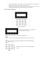
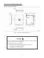
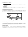
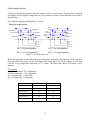
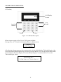
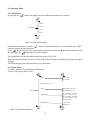
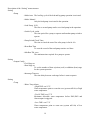
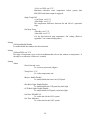
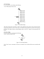
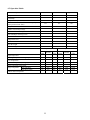
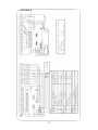
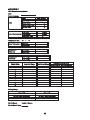
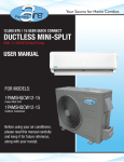
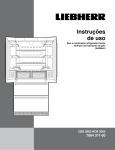
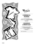
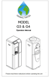
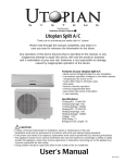
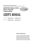
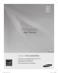
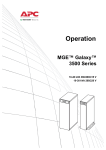
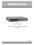
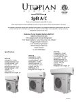
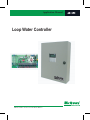
Application Manual
Loop Water Controller
AM - LWC
TABLE OF CONTENTS
ii
LIST OF FIGURES
iii
1.0 SAFETY CONSIDERATION
1.1 Installation Recommendations
1
1
2.0 GENERAL DESCRIPTION
2.1 General Introduction
2.2 LWC Features
2.3 Operation Condition
2.4 Installation site
2
2
2
4
4
3.0 HARDWARE DESCRIPTION
3.1 LWC Hardware Outlook
3.2 LWC Control Box
3.3 Sensor
3.3.1 Water Flow Sensor
3.3.2 Outdoor Air Temperature Sensor
3.4 Default Setting Reset Switch
3.5 LCD Panel Key Explanations
5
5
6
7
7
7
7
8
4.0 INSTALLATION/WIRING INSTRUCTION
4.1 LWC Control Box Installation
4.2 Water Temperature Sensor Installation
4.3 Outdoor Air Temperature Sensor Installation
4.4 Sticker Control Box
9
9
10
10
10
5.0 SYSTEM SPECIFICATION
5.1 System On/Off function
5.2 Pump control function
5.3 12 stages of heat rejection and heat addition control
5.4 Pre-heat & Pre-cool
5.5 Outdoor (OD) Air Reset
5.6 Emergency Protection
5.7 Error Description
11
11
11
11
13
14
14
15
6.0 OPERATION USER MANUAL
6.1 Starting
6.2 Operation Menu
6.2.1 Main Menu
6.2.2 Status Menu
6.2.3 Password Protection
6.2.4 Setting Menu
6.2.5 Test Menu
6.2.6 Error Menu
6.3 Operation Limits
16
16
17
17
17
18
18
21
21
22
ii
7.0 SERVICE AND TROUBLESHOOTING GUIDE
7.1 Service
7.2 Troubleshooting Guide
23
23
23
APPENDIX A
APPENDIX B
APPENDIX C
24
25
26
LIST OF FIGURES
Figure 1: Loop Water Controller Internal View
Figure 2: LWC Hardware Outlook
Figure 3: LWC Outlook
Figure 4: LWC Internal View
Figure 5: Water Temperature Sensor
Figure 6: Outdoor Air Temperature Sensor
Figure 7: Dip Switch
Figure 8: LCD Panel
Figure 9: Control Box Outline and Dimension
Figure 10: Water Temperature Sensor Installation
Figure 11: Pre-heat & Pre-cool
Figure 12: Outdoor Air Reset
Figure 13: LCD Panel Description
Figure 14: Main menu Display
Figure 15: Status Menu Display
Figure 16: Setting Menu Display
Figure 17: Test Menu Display
Figure 18: Error Menu Display
2
5
6
6
7
7
7
8
9
10
13
14
16
17
18
19
22
22
iii
1.0 SAFETY CONSIDERATION
Installation and maintenance should be performed by qualified technicians and installers who are
familiar with local code and regulation.
1.1 Installation Recommendations
•
•
•
•
All field wiring must be installed in accordance with the national wiring regulation.
Ensure that the rated voltage of the unit correspond to the name plate before commencing wiring
work according to the wiring diagram.
The unit must be GROUNDED to prevent possible hazard due to installation failure.
Never unplug any cables, printed circuit board terminal blocks, relay modules, or power plugs
when power is applied.
1
2.0 GENERAL DESCRIPTION
2.1 General Introduction
The Water Loop Controller (LWC) is designed for Water Source Heat Pump water loop control system.
This device can be operated as a stand-alone system (without Smart Manager) or a combination of
networking control system (with Smart Manager). The system can operate according to 12 sets of pre-set
data to open or close the heat rejection or heat addition stage for controlling the water loop operation.
Figure 1: Loop Water Controller Internal View
2.2 LWC Features
The LWC is a microprocessor-based control panel designed to provide sophisticated control and
monitoring of the loop water temperature of a water source heat pump system.
Primary control features offered by the LWC are as follows:
•
Loop Circulating Pump Control
Allows 2 loop circulating pumps with manual or auto lead lag control where pump operation is
interchangeable.
•
Heat Rejection & Addition Output Stages
There is a total of 12 sets of data output can be pre-set as heat addition or heat rejection stages.
•
Sensor:
i) Outdoor (OD) Air Temperature Sensor
ii) Water Temperature Sensor
2 types of sensors are used to sense the OD air temperature and water temperature.
2
•
Alarm/Indication
An additional alarm/indication output can be used to give a signal if there is an error during the
system operation. Attention is needed when the alarm/indication is activated.
A buzzer is installed in the LCD panel and will be activated when there is an error occurs.
•
Emergency Shutdown (EM1, EM2)
The Loop Water Controller monitors the water loop pump status and high/low loop temperature
conditions. Should the water loop pump fail or loop temperature exceeds the predefined limits,
the LWC will close a set of contacts and put all units into the emergency shutdown mode (with
network controller).
•
Remote On/Off Switch:
•
Remote Reset Input
The remote reset input switch is used to reset the system when error occurred without restart the
power supply of the system.
•
Water Flow Switch Input
A water flow switch input is used to detect the availability of water supply to the system.
•
High and Low Water Temperature Protection
A water sensor is used to measure the water temperature. It protects the system by sending error
signal and shutoff the system when water temperature is too high/low.
•
Pre-heat & Pre-cool
The system is able to provide protection for the temperature exceeding the too high/low
temperature when the system is Off.
•
Outdoor (OD) Air Reset
The heat addition On/Off limit setting of the system is able to be increased in a response to a
drop in the OD air temperature.
•
LCD Panel
The LCD panel interface consists of LCD screen and keypad. All operating conditions, system
alarms and errors, water loop system setting, and test menu can be monitored and set from this
LCD panel.
•
Password Protection
Password entry is needed for authority to change the setting and configuration of the system.
i) On/Off Switch
ii) Network Controller
The LWC On/Off system is by using either i) On/Off Switch, or ii) Network Controller system,
to start/stop the operation of the LWC system.
3
2.3 Operation Condition
The operating condition of LWC is as the following:
Temperature
: 0-50°C
Relative Humidity
: 0-95%
Input Voltage Limits : 198~264VAC 50 Hz
2.4 Installation Site
The LWC is designed for indoor installation only (not water proof). Make sure there is sufficient space
for service and maintenance.
Avoid installation at the following location:
• Exposure to shocks, heat, rain, water leakage or direct sunlight
• Any source of electromagnetic pollution
• Installation on uneven vertical surface
4
3.0 HARDWARE DESCRIPTION
3.1 LWC Hardware Outlook
Hardware contacts specification:
S1
S2, S3
Output 1 – 12
Pump 1&2
Alarm
EM1
EM2
: 12Vdc, Ground
: 24Vac
: 220~240Vac, 3A
: 220~240Vac, 3A
: 220~240Vac, 3A
: 12Vdc
: Ground
Note: Unit in mm
Figure 2: LWC Hardware Outlook
5
3.2 LWC Control Box
Figure 3 shows the outlook and dimension of LWC control box.
Figure 3: LWC Outlook
Figure 4 shows the internal structure of LWC.
Figure 4: LWC Internal View
6
3.3 Sensor
3.3.1 Water Temperature Sensor
Connect the 2 wires of water temperature sensor to the terminal block T1, T1.
Figure 5: Water Temperature Sensor
3.3.2 Outdoor Air Temperature Sensor
Connect the 2 wires of outdoor air temperature sensor to the terminal block T2, T2.
Figure 6: Outdoor Air Temperature Sensor
3.4 Default Setting Reset Switch
SW1
ON
1
8
OFF
RED LED
GREEN LED
Figure 7: Dip Switch
The SW1 switch on top of the red and green led on the LWC is used to reset the system setting to the
default setting. Two conditions are applied:
7
•
After the power supply is Off, switch the switch 1 to the ON position. Turn On the power
supply and it will set the system setting to the default setting.
After the power supply is Off, switch the switch 1 to the OFF position. Turn On the
power supply and it will set the system setting to the previous memory.
•
3.5 LCD Panel Key Explanations
Figure 8: LCD Panel
This display screen show two rows of data where
each row contains 16 characters.
Enter key is used to execute the navigation instruction.
Esc key is used to cancel the navigation instruction/ back to previous menu.
The 2 arrows keys permit page scrolling, item selection and modifying the
selected value.
.
The numbered keys are used to change the parameter
setting.
8
4.0 INSTALLATION/WIRING INSTRUCTION
4.1 LWC Control Box Installation
Figure 9: Control Box Outline and Dimension
Caution !
The LWC is designed for indoor installation only (not water proof). Make sure there
is sufficient space for service and maintenance.
Avoid installation at the following location:
• Exposure to shocks, heat, rain, water leakage or direct sunlight
• Any source of electromagnetic pollution
• Installation on uneven vertical surface
9
The installation of the LWC control box:
With Smart Manager (optional)
• Connect the terminal in the control box with the necessary wires to Smart Manager according to
APPENDIX A.
12Vdc Adaptor
• A 12Vdc adaptor is needed to supply the voltage to the Smart Manager if power supply (12Vdc,
Ground) from LWC is not wired to Smart Manager.
4.2 Water Temperature Sensor Installation
The installation of the water temperature sensor is as the figure 10. The sensing element is at the end
point of the sensor. The end point of the sensor should be placed at the center of the pipe as counter to
the water flow. Do not place the end point of the sensor near or touching the pipe hose.
Figure 10: Water Temperature Sensor Installation
4.3 Outdoor Air Temperature Sensor Installation
The installation of the OD air temperature sensor is needed to be placed at the open space. Do not place
the sensor near the heating/cooling object which will affect the reading of the sensor.
4.4 Sticker Control Box
The sticker of wiring diagram and external wires connection guidelines are placed inside the LWC
control box in order to have the correct guidance for installation. Both of the diagrams are shown in
APPENDIX B.
10
5.0 SYSTEM SPECIFICATION
5.1 System On/Off
Using remote On/Off switch (S1):
i)
Standard Switch (without Smart Manager)
ii)
Smart Manager
to start or stop the operation of the LWC.
The LWC shall function as:
• System On if the remote On/Off switch (S1) is in closed circuit.
• System Off if the remote On/Off switch (S1) is in opened circuit.
5.2 Pump control function
In automatic mode:
Once the system is On, the LWC will initialize the lead pump when there is a requirement for heat
rejection or addition output to operate and also during pre-cool or pre-heat operation. 10 seconds after
the lead pump is On, checking will be done on water flow switch. This checking is done for 15 seconds
(adjustable). If the water flow switch detects no water flow, the lead pump will be Off, error is shown on
display, alarm output is triggered and buzzer will be activated. Then the lag pump will be On. 10
seconds after the lag pump is On, the checking on the water flow switch will be done for 15 seconds
(adjustable). If after 15 seconds the water flow switch still cannot detects water flow, the system will be
Off, error is shown on display, alarm output is triggered and buzzer will be activated. Then, the
emergency shut down (EM1, EM2) will be activated.
The lead pump-lag pump sequence is automatically changed based on pump switch cycle time
(adjustable).
In manual mode:
Only one pump can operate if the pump is set as manual mode. Either one of the pump can be set to
operate when the system is On. The checking on the water flow is the same as the lead pump in
automatic mode. This mode will not have lead – lag cycle.
If the water problem is verified and fixed, user can reset the remote switch (S2) and the pump will
resume operation. Alternatively it can be reset by power supply.
5.3 12 stages of heat rejection and heat addition control
A total of 12 stages of heat rejection and heat addition control can be established according to pre-set
temperature range. The heat rejection and heat addition temperature setting shall be distributed in
sequence and continuous (difference by 1ºC). The Table 1 and Table 2 below show an example of stages
temperature setting.
Condition of the following example setting:
i. 4 heat addition output stages (adjustable) and 8 heat rejection output stages (adjustable).
ii. Heat reject and add stage temperature differential of 3ºC (adjustable)
iii. Heat addition stage temperature: 20 ºC (adjustable)
Heat rejection stage temperature: 30 ºC (adjustable)
11
Table 1: System setting temperature (ºC)
1# (OUT1)
On
Limit
Setting (ºC)
17
Off
Limit
Setting (ºC)
20
Heat add stage 4
2# (OUT2)
18
21
Heat add stage 3
3# (OUT3)
19
22
Heat add stage 2
4# (OUT4)
20
23
Heat add stage 1
5# (OUT5)
30
27
Heat reject stage 1
6# (OUT6)
31
28
Heat reject stage 2
7# (OUT7)
32
29
Heat reject stage 3
8# (OUT8)
33
30
Heat reject stage 4
9# (OUT9)
34
31
Heat reject stage 5
10# (OUT10)
35
32
Heat reject stage 6
11# (OUT11)
36
33
Heat reject stage 7
12# (OUT12)
37
34
Heat reject stage 8
Output Stages
Function
Table 2: System setting temperature (ºF)
1# (OUT1)
On
Limit
Setting (ºF)
59
Off
Limit
Setting (ºF)
64
Heat add stage 4
2# (OUT2)
61
66
Heat add stage 3
3# (OUT3)
63
68
Heat add stage 2
4# (OUT4)
65
70
Heat add stage 1
5# (OUT5)
85
80
Heat reject stage 1
6# (OUT6)
87
82
Heat reject stage 2
7# (OUT7)
89
84
Heat reject stage 3
8# (OUT8)
91
86
Heat reject stage 4
9# (OUT9)
93
88
Heat reject stage 5
10# (OUT10)
95
90
Heat reject stage 6
11# (OUT11)
97
92
Heat reject stage 7
12# (OUT12)
99
94
Heat reject stage 8
Output Stages
Function
Example of description:
From the Table 1 above, if OUT4 is set as Heat addition stage1, OUT3 – OUT1 will be automatically
recognized as Heat addition stage2 – Heat addition stage4. In the mean time, OUT5 – OUT12 will be
automatically be set as Heat reject stage1 – Heat reject stage8.
The temperature differential (3 ºC) will determine the On and Off limit setting by 3 ºC difference.
On and Off limit setting shall be arranged in the form from the lowest to the highest.
Every changing (On/Off) of stages will have a delay time of 15 seconds (adjustable), before the next
changes.
This system setting applied the same for, temperature unit: degree Celsius (ºC) and degree Fahrenheit
(ºF).
12
5.4 Pre-heat & Pre-cool
This pre-cool & pre-heat operates when the system is Off (S1 open circuit). This function is activated
according to the too high/low temperature set. The operation and setting of this function is described as
the following:
Pre-cool/heat temperature differential: 5ºC (fixed)
When S1 is open circuit
Close
Heat-reject 3
Close
Heat-reject 2
Close Heater 3
Open Heater 3
Close Heater 2
Open Heater 2
Close Heater 1
Open Heater 1
Close
Heat-reject 1
Pre_Th + 5
Pre_ Th + 3
Pre_Th
Pre_Th - 2
Pre_Th: Pre_heat temperature
Open
Heat-reject 3
Open
Heat-reject 2
Open
Heat-reject 1
Pre_Tc + 2
Pre_Tc
Pre_Tc - 3
Pre_Tc - 5
Pre_Tc: Pre_cool temperature
(Pre_Th = Too low temperature)
(Pre_Tc = Too high temperature)
Figure 11: Pre-heat & Pre-cool
When the temperature reaches the too high/low temperature (adjustable), this function will be activated,
the pump and output stages will On accordingly. The output stages will Off accordingly as well with
reference to the temperature differential of 5ºC (fixed). The table below shows an example of this
function.
For example:
Too high temperature: 43ºC (adjustable)
Too low temperature: 10ºC (adjustable)
No. of heating stage: 3 (adjustable)
No. of cooling stage: 3 (adjustable)
Stage
On Temp (℃)
Off Temp (℃)
Heating stage 3
8
13
Heating stage 2
9
14
Heating stage 1
10
15
Cooling stage 1
43
38
Cooling stage 2
44
39
Cooling stage 3
45
40
13
5.5 Outdoor (OD) Air Reset
Outdoor air reset will be incorporated into the current LWC. It will increase the heat addition stages set
point to increase the unit performance in heating mode. The heat addition set points shall be able to be
increased in a response to a drop in outside air temperature. The set point increase shall be operator
defined from 1°C (2°F) to 5°C (10°F) in response to a drop in outside air temperature from 16°C (61°F)
to -17°C (1°F). This ramp shall be linearly proportional.
OD Air Reset
Range (°C)
-17
-8
0
8
16
OD Air
Temp (°C)
Figure 12: Outdoor Air Reset
5.6 Emergency Protection
1) Low/Too Low temperature
If the water flow temperature is lower than 13°C (adjustable), the alarm will be activated for 20
times/minute; if the water flow temperature is lower than 10°C (adjustable), the alarm will be
activated for 100 times/minute, the emergency switch, EM1 and EM2 signal will be sent out. The
alarm/buzzer will activate continuously.
2) High/Too High temperature
If the water flow temperature is higher than 40°C (adjustable), the alarm/buzzer signal will be
activated for 20 times/minute; if the water flow temperature is higher than 43°C (adjustable), the
alarm/buzzer signal will be activated for 100 times/minute, the emergency switch, EM1 and EM2
will send signal to Off the system, with the alarm activates 100 times/minute continuously.
3) Loss of Flow
For automatic mode pump control, the lead pump is On first. The water flow switch will start to
check for water flow after 10s. If it gives an error signal after checking of 15 seconds (adjustable),
the lead pump will be Off with the alarm activates 20 times/minute, and the lag pump will On. If the
water flow switch give an error signal after another checking of 15 seconds (adjustable), the lag
pump will be Off and the emergency switch, EM1 and EM2 will send signal to Off the system, with
the alarm activates 100 times/minute continuously.
4) Sensor Error
If either the Water Supply sensor or OD Air sensor or both of them gives an error signal (due to
disconnection or not in function) during the system operates, the alarm will activate 20 times per
minute. The unit will be Off. All heat rejection and heat addition stages shall be shut down.
14
5.7 Error Description:
ERR Description
LCD Panel Code
Water Sensor Error
Water Sensor ERR
Low Water Temperature
Water Low Temp
High Water Temperature
Water High Temp
Water Pump1 Flow Failure
Flow Error Pump1
Water Pump2 Flow Failure
Flow Error Pump2
Too High Water Temperature Shutdown
Hi Temp Shutdown
Too Low Water Temperature Shutdown
Lo Temp Shutdown
Outdoor Sensor Failure
OD Sensor ERR
The table above shall be referred when there is any errors occur during the operation of the system.
Error code will be shown differently at different hardware display whenever there is an error occurs. The
“Error” LED on the LCD panel will blink when there is any error occurs.
Water Sensor Error/Outdoor Sensor Failure
– There will be an error signal and unit will be Off when the water sensor and OD sensor fail to operate
during the system On. The alarm will Off and unit will return to normal operation once the water sensor
and OD sensor error is fixed.
Low Water Temperature/High Water Temperature
– There will be an error signal when the water temperature is in the *warning temperature (adjustable).
The unit is still in normal operation with the alarm signal on. Once the water temperature is falls in the
preset range again, the alarm is Off and unit will operate normally.
Too High Water Temperature Shutdown/Too Low Water Temperature Shutdown
– The LWC will send out the emergency shutdown (EM1, EM2) and alarm signal when the water
temperature is in the **maximum allowable temperature (adjustable). The unit is still in normal
operation with the alarm signal on. Once the water temperature falls in the preset range again, the alarm
and EM1, EM2 will be Off. The unit will operate normally. Too High temperature must be higher than
High temperature setting and Too Low temperature must be lower than the Low temperature setting.
Water Pump1 Flow Failure/Water Pump2 Flow Failure
– The error can be eliminated by the reset On/Off switch and system will be reset. The alarm signal can
be Off by pressing any button on the LCD panel, but error code will keep appearing on the hardware
display until reset On/Off switch is set.
* Warning temperature is the water temperature between the low water temperature (adjustable) and the
too low water temperature (adjustable); and the temperature between high water temperature
(adjustable) and too high water temperature (adjustable).
** Maximum allowable temperature is the water temperature lower than the too low water temperature
(adjustable); and the temperature higher than the too high water temperature (adjustable).
15
6.0 OPERATION USER MANUAL
6.1 Starting
LCD Display
Screen
Menu
Scroll
Key Pad
Numbers
Escape
Enter
Figure 13: LCD Panel Description
When the power supply is On, “Power” LED (green) is lighted.
Start-up screen for 3 second, the information shown in display screen:
McQuay
LWC Controller
After showing the start-up screen, the screen proceeds with the default display. The default display is the
water temperature and the highest stage of heat rejection or addition. User can enter into the main menu
and 4 sub menus. The menu display will return to default display if it remained idle for 30 seconds.
The default display shows:
Water Temp: xx ºC
Cooling Stage xx (or Heating Stage xx)
16
6.2 Operation Menu
6.2.1 Main Menu
By pressing the
button, the display screen will shows main menu item, as below.
Status
Setting
Main menu
Test
Error
ESC
Figure 14: Main Menu Display
In all the menu structure, press the
button to proceed with the next level of menu, press “ESC”
button to return to the previous menu.
Press
button when there is a setting condition for the item, press the ▲ or numbers button to select
the item. Press the
button again to set the changes.
The setting menu can only be modified when the system (S1) is Off.
When the specific parameter to be set is out of the range, the panel will notify the operator by popup
message.
The following pages show the structure of every main menu.
6.2.2 Status Menu
In “Status” menu the screen displays the following:
“Power” LED (green colour) is On;
1#: On (Off)
2#: On (Off)
Pump
Water Flow: Yes (No)
Water Temp: xxx°C (°F)
OD Temp: xxx°C (°F)
Temp
Status
Output Stage
Pump Run Time
Figure 15: Status Menu Display
ESC
1#: Cool (Heat) On (Off)
On: xxx Off:xxx°C (°F)
2#: Cool (Heat) On (Off)
On: xxx Off:xxx°C (°F)
(3-12#): Unused
Pump1: xxhr
Pump2: xxhr
ESC
17
User can view the system condition according the structure shown in the figure 15.
6.2.3 Password Protection:
4 digits password entry is needed to enter and change “Setting” and “Test” menu. The default password
is 8888. Password access is denied when there is more than 3 times of invalid password keyed in. It will
automatically return to the default display after pressing the “Enter” button or after 3 seconds. It will
also prohibit the user from accessing the “Setting” and “Test” menu for 10 minutes.
If user forgets the password, the password can be reset by pressing the button behind the LCD panel.
Password recovered to default 8888.
6.2.4 Setting Menu
When LWC system is operating, user can only view the detail setting but cannot made changes in this
sub menu.
In “Setting” menu the screen displays the following:
“Setting” LED (red colour) is On;
Pump
Output Config
Setting
Temp
Mode: Auto (Manual)
Lead Pump: 1# (2#)
Switch Cycle: xxxhr
Pump Switch Check Time:xxxs
Reset Run Time
Min Run TM: xxxs
Cool Stage: xx
Heat Stage: xx
Interstage Time: xxs
Water Temp Alarm
High TMP: xxx°C (°F)
Too Hi TMP: xxx°C (°F)
Low TMP: xxx°C (°F)
Too Low TMP: xxx°C (°F)
Stage Temp Diff
Cool Stage: xxx°C (°F)
Heat Stage: xxx°C (°F)
Set Stage Temp
Heat Rej: xxx°C (°F)
Heat Add: xxx°C (°F)
ODA reset Enable (Disable)
ESC
OD reset TMP: xxx°C (°F)
Other
ESC
New Password: xxxx
Temp Unit: °C (°F)
Buzzer: Enable (Disable)
Key Back Light: Enable (Disable)
LCD Back Light: Enable (Disable)
Date: DD-MM-YY
Set Time: hh:mm:ss
ESC
Figure 16: Setting Menu Display
18
Description of the “Setting” menu structure:
Setting
>Pump
>Mode:Auto The lead lag cycle of the lead and lag pump operation is activated.
>Mode: Manual
Only the lead pump is activated in the operation.
>Lead Pump: 1#/2#
The first or second pump can be set as lead pump in the operation.
>Switch Cycle: xxxhr
The time period for a pump to operate until another pump switch to
operate.
>Pump Switch Check Time:
The time to check the water flow after pump is On for 10s.
>Reset Run Time
To reset the record of the total pump run time to 0 hour.
>Min Run TM: xxxs
The minimum time required for a pump to operate.
Setting
>Output Config
>Cool Stage:xx
>Heat Stage:xx
To set the number of heat rejection (cool) or addition (heat) stage
for the system operation
>Interstage Time:xxs
The time delay between each stage before is start to operate.
Setting
>Temp
>Water Temp Alarm
>High TMP: xxx°C/°F
Water temperature point to warn the user (system still On) of high
water temperature.
>Too Hi TMP: xxx°C/°F
Maximum allowable water temperature before EM1,EM2 and
Alarm output is triggered.
>Low TMP: xxx°C/°F
Water temperature point to warn user (system still On) of low
water temperature.
19
>Too Low TMP: xxx°C/°F
Minimum allowable water temperature before system shut
EM1,EM2 and Alarm output is triggered.
>Stage Temp Diff
>Cool Stage: xxx°C/°F
>Heat Stage: xxx°C/°F
The temperature difference between On and Off of a particular
stage.
>Set Stage Temp
>Heat Rej: xxx°C/°F
>Heat Add: xxx°C/°F
It is the first heat/cool stage temperature ‘On’ setting. (Refer to
Appendix C for commissioning sheet)
Setting
>ODAresetEnable/Disable
To enable/disable the Outdoor Air Reset function.
Setting
>ODresetTMP: xxx°C/°F
The range of temperature to be set for heat addition that refers to the outdoor air temperature. It
can only be set when the ‘ODAreset’ is enable.
Setting
>Other
>New Password: xxxx
To set a new password (4 digits).
>Temp Unit: °C/°F
To set the temperature unit.
>Buzzer: Enable/Disable
To enable/disable the buzzer on LCD panel.
>Key Back Light: Enable/Disable
To enable/disable the LCD panel key back light.
>LCD Back Light: Enable/Disable
To enable/disable LCD panel screen back light.
>Set Date: DD-MM-YY
To set the date for the LWC system.
>Set Time: hh:mm:ss
To set the time for the LWC system.
20
6.2.5 Test Menu
In “Test” menu the screen displays the following
“Test” LED (orange colour) is On;
Test
1#Pump: On (Off)
2#Pump: On (Off)
1#Stage: On (Off)
2#Stage: On (Off)
3#Stage: On (Off)
4#Stage: On (Off)
5#Stage: On (Off)
6#Stage: On (Off)
7#Stage: On (Off)
8#Stage: On (Off)
9#Stage: On (Off)
10#Stage: On (Off)
11#Stage: On (Off)
12#Stage: On (Off)
Buzzer: On (Off)
Alarm Out: On (Off)
ESC
Figure 17: Test Menu Display
The LWC provides the Test menu to check on the operation of the system. The Test menu must be
operated only when the system is Off or dry run. Under the testing menu, the operation of the system is
prohibited. The display returns to default display when it is idle for 3 minutes or by pressing the ESC
button.
6.2.6 Error Menu
In “Error” menu the screen displays the following
“Error” LED (red colour) is On;
History
Error
Delete
ESC
Figure 18: Error Menu Display
In the “Error” menu, a maximum of 10 errors is recorded. User can delete all the errors recorded in this
menu.
21
6.3 Operation Limits
Description
Lower Limit
Default
Upper Limit
Pump: Auto/Manual
NA
Auto
NA
Lead Pump
NA
1#
NA
Pump Switch Cycle (Auto)
Water flow detection check time after 1st pump On
(Pump Switch Check Time)
8hr
88hr
168hr
15s
15s
60s
30s
40s
240s
Number of Heat Reject Stage
0
8
12
Number of Heat Add Stage
0
4
12
Heat Add/Reject Interstage Time
10s
15s
200s
Password
NA
8888
NA
Temperature Unit
NA
ºC
NA
Buzzer
NA
Disable
NA
Key Back Light
NA
Disable
NA
LCD Back Light
NA
Disable
NA
Pump Minimum Run Time
Temp unit (ºC)
High Temperature
Lower
Limit
30ºC
Temp unit (ºF)
40ºC
Upper
Limit
44ºC
Lower
Limit
86ºF
Default
104ºF
Upper
Limit
111ºF
Default
Too High Temperature (emergency shutdown)
31ºC
43ºC
45ºC
87ºF
109ºF
113ºF
Low Temperature
6ºC
13ºC
18ºC
42ºF
55ºF
64ºF
Too Low Temperature (emergency shutdown)
5ºC
10ºC
17ºC
41ºF
50ºF
62ºF
Stage Temperature Differential
Heat Add Stage
Stage Temperature
Heat Reject Stage
1ºC
3ºC
5ºC
2ºF
6ºF
10ºF
7ºC
7ºC
1ºC
20ºC
30ºC
5ºC
43ºC
43ºC
5ºC
44ºF
44ºF
2ºF
64ºF
86ºF
10ºF
109ºF
109ºF
10ºF
OD Air Reset Temperature
22
7.0 SERVICE AND TROUBLESHOOTING GUIDE
7.1 Service
Service should be performed by authorized dealer or qualified contractor.
Caution
•
•
•
!
Do not attempt to do any service or maintenance when the unit is operating.
Off the main power supply before doing maintenance.
Unauthorized modification of the unit is not allowed.
7.2 Troubleshooting Guide
Trouble shooting must be performed by authorized dealer or qualified contractor.
Fault
LWC cannot start
Check Point
• Check power supply plug
• Check wiring and S1 contact connection
• Circuit breaker or fuse tripped/blown
No display on LCD screen or LCD
• Check wiring and contact connection
keypad not in function
• Restart power supply
Alarm is not in function
• Check wiring and contact connection
• Check alarm condition
Sensor Error
• Check wiring and contact connection
• Check sensor condition
Sensor temperature not accurate
• Wiring length (resistance) affects the reading
Pump not in operation
• Water temperature too high/low
• Check water flow switch & water supply valve
• Check piping condition
• Check pump internal wiring connection
Pump not switching
• Check pump setting: Set pump in Auto mode
Heat add/reject stages not in function or
• Check wiring and contact connection
Operation not according to system
• Check output configuration setting: Set output
setting
configuration accordingly
• Check cooler/cooling tower and heater/boiler
condition
OD Air Reset not in function
• Check OD Air Reset setting:
• Enable the OD Air Reset item
Kindly contact the dealer if none of these checks solve the problem.
23
APPENDIX A
24
APPENDIX B
25
APPENDIX C
LWC Commissioning Sheet
Date:
Person Incharge:
Mode:
Auto / Manual
Lead Pump:
Pump
Switch Cycle:
hr
Switch Check Time:
s
Min Run Time:
s
Heat Add:
Output Configuration Heat Reject:
Interstage Time:
Temperature Unit:
Stage Temperature
1/2
°C
/
stages
stages
s
°F
Heat Add:
Heat Reject:
Cool Stage:
Temperature
Differential
Heat Stage:
Cool Stage:
Heat Stage:
Temperature
Differential
Output Relay
Heat Add Stage
Heat Reject Stage
Temperature differential
On Limit Setting Off Limit Setting
1
2
3
4
5
6
7
8
9
Setting Range:
Low Temp
High Temp
Too Low Temp (Shutdown)
Too High Temp (Shutdown)
OD Air Reset:
Enable / Disable
OD Air Reset Temp:
26