1
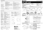
16-Port 10/100Mbps Smart Switch (VLAN, Trunking & Fiber Option) ES-3116RE+ User’s Manual FCC Class B Certification This device complies with Part 15 of the FCC Rules. Operation is subject to the following conditions: 1.This device may not cause harmful interference, and 2.This device must accept any interference received, including interference that may cause undesired operation. Warning! This equipment has been tested and found to comply with the limits for a Class B digital device, pursuant to Part 15 of the FCC Rules. These limits are designed to provide reasonable protection against harmful interference in a residential installation. This equipment generates, uses and can radiate radio frequency energy and, if not installed and used in accordance with the instructions, may cause harmful interference to radio communications. However, there is no guarantee that interference will not occur in a particular installation. If this equipment does cause harmful interference to radio or television reception, which can be determined by turning the equipment off and on, the user is encouraged to try to correct the interference by one or more of the following measures: • Reorient or relocate the receiving antenna. • Increase the distance between the equipment and receiver. • Connect the equipment into an outlet on a circuit different from the one which the receiver is connected to. • Consult the dealer or an experienced radio/TV technician for help. You are cautioned that changes or modifications not expressly approved by the party responsible for compliance could void your authority to operate the equipment. 1. Introduction Congratulations on your purchase of this 16-port Smart Fast Ethernet Switch. This high performance switch provides sixteen fast ethernet ports to segment network traffics, extend fast ethernet connection distance, and convert data packets between different transmission speeds. This Switch provides sixteen shielded RJ-45 ports. These are 10BaseT/100BaseTX Auto-negotiation ports. This switch utilize stored-and-forward switching architecture that filters and forwards data after the complete data packet is received and examined to be free of errors. With one set of status LEDs for each individual port, the switch operation status can be easily monitored. It’s rackmount design that can be mounted on the industrial standard 19 inches rack in the enterprise wiring center. This switch supports both full & half duplex on all ports which are able to provide 200Mbps of bandwidth to the connected devices, with auto-negotiation providing smooth migration from Ethernet to Fast Ethernet. It also supports backpressure and IEEE 802.3x advanced flow control capability that can reduce congestion and prevent packet loss. And it offers advance features : VLAN : Port based VLAN allows you to set virtual LANs within your network Trunking : Reduce the bottleneck between swtiches Fiber Option : Provide one fiber module option 2. Features & Specifications (1) Features Comply with IEEE 802.3 10BaseT and IEEE 802.3u 100BaseTX Standards. Provide 16 UTP ports with 10/100Mbps Auto-Negotiation. Provide one uplink port which can connect to another hub/switch using a normal UTP cable One 100Mbps Fiber-SC/ST Full/Half Duplex) module option (Support Support IEEE 802.3x compliant full-duplex flow control, half-duplex flow control Full wire speed on every port. Support Port-based VLAN Support 2 Trunking Group Standard 19” rackmount size. Support store-and-forward switching architecture. (2) Specifications Standards : IEEE 802.3 10BaseT and IEEE 802.3u 100BaseTX 10/100Mbps Ports : RJ-45 x 16 Uplink Port : RJ-45 x 1 100Mbps Fiber-SC/ST Port : Optional Switching Architecture : Store and Forward MAC Address : 8K Buffer : 512Kbyte Flow Control : Back pressure and IEEE 802.3x VLAN : Port-based VLAN up to 16 groups Trunking : 2 groups N-Way Auto-Negotiation : on all ports Full-Duplex / Half-Duplex : on all ports Switch LED : Power Port LEDs : Link/Activity, 100M, Collision/Full-Duplex Power : 100~240V AC, full range internal power Emission : FCC Class B , CE Mark , C-tick 3. Package Contents One Fast Ethernet Switch One Power Cord One User’s manual Rackmount accessories 4. Physical Description (1) Panel Front View LED Control Button RJ-45 Connectors Rear View Power Connector AC 100-240V SW I o POWER Expansion Slot Power Switch LED/Button Panel Normal : Full Duplex / Collision Setup : Group Normal : 100Mbps Setup : Port Power LED Normal : Link / Activity Setup : Status Setup Functions Setup Buttons (2) LED LED System Power FUL/COL ( Fu ll D up lex/ C o l lis io n) Status Description On Power is supplied Off No Power On Collision detected in this segment Off No Collision Flash A valid link is established Data packets received Off No link is established On Normal Port LNK/ACT (Link /Ac tivity) 100M (100Mbps) On Off On Group Setup Status Off On Port Off On Status VLAN TRUNK Setup 10/100M Function FULL/HALF SAVE Off On Off On Off On Off On Off On Off This port run at 100Mbps No connected or run at 10Mbps This group is in setting mode This group is not in setting This port is in setting mode This port is not in setting mode This port is selected This port is not selected VL AN is in setting mode VL AN is not in setting mode Trunking is in setting mode Trinking is not in setting mode Speed is in setting mode Speed is not in setting mode Full/Half duplex is in setting mode Full/Half duplex is not in setting mode Save function is in setting mode Save function is not in setting mode 5. Installation (1) Operating Environment This 16 ports smart switch must be installed and operated within the limits of specified operating temperature and humidity (see previous section under Specifications). Do not place objects on top of the unit. Do not obstruct any vents at the sides of the unit. Do not position the unit near any heating source such as heater, radiator, or direct exposure to sun. Prevent entering of water and moisture into the unit. If necessary, use dehumidifier to reduce humidity. (2) Connecting network devices The RJ-45 ports on the switch are designed as MDI-X ports which allow using straight-through cables to connect this switch to workstation or hub’s uplink port (MDI). A crossover cable must be used to connect the switch directly to a hub’s regular port. Connect one end of the network cable to the RJ-45 port on the front panel, and connect the other end of the network cable to the RJ-45 port on the network device. Follow the same procedure to connect all the RJ-45 ports of the switch. The UTP network cables must comply with EIA/TIA 568 specifications and Category 5 standard for 100Mbps data transmission. Maximum length, using UTP cable, between the switch and connected device is 100 meters (300ft). Once the network cable is connected to both ends and the attached network device is powered on, the green LNK/ACT LED should be lit. An uplink port is located right next to the 16th port of this switch. The uplink port is a shared port with the 16th port but provides the MDI connecting to another hub/switch using regular straight-through cables. Otherwise if you have bought our fiber option module that you can expansion to 1.5k meters (5000ft) between the switch and connected device. (3) Connecting the power Connect the power cord to the power socket on the rear panel of the unit. Connect the power cord to the power outlet and turn on power switch. The Power LED on the front panel should be lit. 6. Advance Configuration This switch provides advance features which offer you more flexibility in setting up your network. The following section explain how to setting up the VLAN, Trunking, Speed and Full/Half duplex modes. (1) VLAN Virtual LAN (VLAN) is a logical subgroup within a local area network which can be configure through port configuration. VLAN can be configured to optimize traffic or to isolate specific workstations for reasons of security or convenience. Each VLAN you configure behaves as an isolated broadcast domain just as if it were a separate switch. There is no communication between ports on the separate VLANs unless the VLANs are connected by an external router. VLAN Group 1 VLAN Group 2 VLAN Group 3 VLAN Configuration This Switch provides sixteen VLAN groups. Please refer to the following procedure to configure VLAN: Step 1. Press the Function button until the VLAN LED is on. Step 2. Press the Group button to scroll between the VLAN groups 1 to 16. Step 3. Press the Port button to scroll between the port 1 to 16. Step 4. Press the Set button to assign the selected port to the VLAN group. After you press Set button ,the selected port LED will switch between on and off. If the selected port LED is on, the selected port is added to the VLAN group. If the selected port LED is off, the selected port is removed from the VLAN group. Step 5. Repeat steps 3 to 4 to assign other ports to the selected VLAN group. Step 6. When you finish one VLAN group configuring, press the Group button to scroll to the next VLAN group. Repeat steps 3 to 4 and assign ports to the new group. Step 7. Press the Function button until the SAVE LED is on. Step 8. Press the Set button to save the setting. Step 9. Press the Function button to return to normal mode. (2) Trunking This switch provides the port trunking function which can help user to reduce the bottleneck by providing more than one connection between two switches. 1.2Gbps Trunk 800Mbps Trunk 1.2Gbps Trunk and 800Mbps Trunk Port trunking Configuration This switch provides two Port trunking groups listed in following table. Group A B Mode Ports Description 1 1,9 two ports trunking 2 1, 2, 9, 10 four ports trunking 3 1, 2,3,9,10,11 six ports trunking 1 7,15 two ports trunking 2 7,8,15,16 four ports trunking The following instructions describe how to configure port trunking. Note : 1.Trunking port work in 100M full-duplex. 2.The trunking ports must be configured to the same VLAN group. Step 1. Press the Function button until the Trunking LED is on. Step 2. Press the Group button to select Group A and Group B Step 3. Press the Port button to scroll between trunk mode 1 to 3 (Group A) or mode 1 to 2 (Group B). Step 4. Press the Function button until the SAVE LED is on. Step 5. Press the Set button to save the setting. Step 6. Press the Function button to return to normal mode. (3) Speed (100M / 10M) Configuration This switch provides the force speed function. You can refer the following procedure to setup the speed of switching ports. Step 1. Press the Function button until the Speed LED is on. Step 2. Press the Port button to scroll between the port 1 to 16. Step 3. Press the Set button to assign the speed of selected port to 100Mbps or 10Mbps. After you press Set button ,the selected port’s 10M (Status) LED and 100M (Group) LED will switch between on and off. If the selected port’s 10M LED is on and 100M LED is off, the select port is forced to 10M. If the selected port’s 10M LED is off and 100M LED is on, the select port is forced to 100M. If the selected port’s 10M LED is on and 100M LED is on, the select port is set to auto sensing. Step 4. Press the Function button until the SAVE LED is on. Step 5. Press the Set button to save the setting. Step 6. Press the Function button to return to normal mode. (4) Full/Half-Duplex Configuration This switch provides the force Full/Half Duplex Mulde function. You can refer the following procedure to setup the full/half duplex mode of switching ports. Step 1. Press the Function button until the Full/Half Duplex LED is on. Step 2. Press the Port button to scroll between the port 1 to 16. Step 3. Press the Set button to assign the selected port to Full or Half Duplex. After you press Set button ,the selected port’s Full (Group) LED and Half (Status) LED will switch between on and off. If the selected port Full LED is on and Half LED is off, the select port is force to Full Duplex. If the selected port Full LED is off and Half LED is on, the select port is force to Half Duplex. If the selected port Full LED is on and Half LED is on, the select port is set to auto negotiation. Step 4. Press the Function button until the SAVE LED is on. Step 5. Press the Set button to save the setting. Step 6. Press the Function button to return to normal mode. 7. Trouble-shooting 1. Power LED is not lit Check if the power cord is properly connected to the power outlet and the hub. Make sure the power switch on the hub is turned ON. 2. 100M Link is not lit when connect to 100Mbps device Check the power switch of the network device attached to the switch; make sure it is turned ON. Check the network cable; make sure it is properly connected to the switch and the network device. Check the network cable; make sure the UTP cables comply with EIA/TIA 568 and Category 5 specification. If normal RJ-45 ports are used to connect to a hub/switch, make sure you have connected to the uplink port and not an regular port. If RJ-45 ports are used to connect to a hub’s regular port, make sure the crossover cable is used. 3. Collision LED flashes constantly Make sure the cable is connected to the uplink port. Check the network cable; make sure it is properly connected to both hubs. One end of the cable should be connected to the first port while the other end of the cable should connected to a regular port. Do not connect the cable to both uplink ports. Check the network cable; make sure the cable complies with EIA/TIA 568 specification. Use CAT5 cables for 100Mbps connection and minimum CAT3 cables for 10Mbps connection. 4. Collision LED flashes constantly Remove all the network cables; connect the cables back one by one to isolate the source of the collision. Check the network cable, inferior cable quality will result in excessive collision and error packets. [!] Contact your dealer if problem persist.