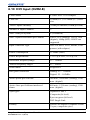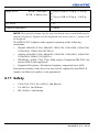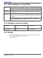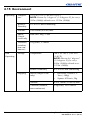
1
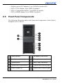
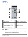
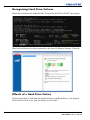
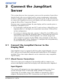
JumpStart Server
Operation Manual
020-100803-01
JumpStart Server
Operation Manual
020-100803-01
NOTICES
COPYRIGHT AND TRADEMARKS
© 2012 Christie Digital Systems USA, Inc. - All rights reserved.
All brand names and product names are trademarks, registered trademarks or trade names of their
respective holders.
REGULATORY
The product has been tested and found to comply with the limits for a Class A digital device, pursuant to
Part 15 of the FCC Rules. These limits are designed to provide reasonable protection against harmful
interference when the product is operated in a commercial environment. The product generates, uses, and
can radiate radio frequency energy and, if not installed and used in accordance with the instruction manual,
may cause harmful interference to radio communications. Operation of the product in a residential area is
likely to cause harmful interference in which case the user will be required to correct the interference at the
user’s own expense.
This Class A digital apparatus complies with Canadian ICES-003.
Cet appareil numérique de la classe A est conforme à la norme NMB-003 du Canada.
이 기기는 업무용 (A 급 ) 으로 전자파적합등록을 한 기기이오니 판매자 또는 사용자는 이점을 주
의하시기 바라며 , 가정 외의 지역에서 사용하는 것을 목적으로 합니다 .
GENERAL
Every effort has been made to ensure accuracy, however in some cases changes in the products or
availability could occur which may not be reflected in this document. Christie reserves the right to make
changes to specifications at any time without notice. Performance specifications are typical, but may vary
depending on conditions beyond Christie's control such as maintenance of the product in proper working
conditions. Performance specifications are based on information available at the time of printing. Christie
makes no warranty of any kind with regard to this material, including, but not limited to, implied warranties
of fitness for a particular purpose. Christie will not be liable for errors contained herein or for incidental or
consequential damages in connection with the performance or use of this material.
The product is designed and manufactured with high-quality materials and components that can be
recycled and reused. This symbol means that electrical and electronic equipment, at their end-oflife, should be disposed of separately from regular waste. Please dispose of the product
appropriately and according to local regulations. In the European Union, there are separate
collection systems for used electrical and electronic products. Please help us to conserve the environment
we live in!
GENERAL WARRANTY STATEMENTS
For complete information about Christie’s limited warranty, please contact your Christie dealer. In addition
to the other limitations that may be specified in Christie’s limited warranty, the warranty does not cover:
a. Damage occurring during shipment, in either direction.
b. Damage caused by misuse, improper power source, accident, fire, flood, lightning, earthquake or other
natural disaster.
c. Damage caused by improper installation/alignment, or by product modification, if by other than a Christie
authorized repair service provider.
d. Problems caused by combination of the equipment with non-Christie equipment, such as distribution
systems, cameras, video tape recorders, etc., or use of the equipment with any non-Christie interface
device.
e. Failure due to normal wear and tear.
f. Warranty does not cover image retention.
PREVENTATIVE MAINTENANCE
Preventative maintenance is an important part of the continued and proper operation of your product.
Please see the Service Manual for specific maintenance items as they relate to your product. Failure to
perform maintenance as required, and in accordance with the maintenance schedule specified by Christie,
will void the warranty.
1 Introduction
1.1 Safety Warnings and Guidelines ........................................................ 1-1
1.1.1 Power Cords and Attachments................................................... 1-1
1.1.2 Symbols and Labels for the Christie JumpStart Server ............. 1-2
1.1.3 General Precautions ................................................................... 1-2
1.1.4 AC / Power Precautions............................................................. 1-2
1.2 Purchase Record and Service Contacts .............................................. 1-3
1.3 Christie JumpStart Server Overview .................................................. 1-4
1.3.1 How the Server Works............................................................... 1-4
1.3.2 List of Components.................................................................... 1-4
1.3.3 Preventing Electrostatic Discharge............................................ 1-4
1.3.4 Installation Guidelines ............................................................... 1-5
1.4 Related Documents............................................................................. 1-6
2 Hardware
2.1 Key Features and Capabilities ............................................................ 2-1
2.2 What’s In the Box?............................................................................. 2-1
2.3 Front Panel Components .................................................................... 2-2
2.3.1 Rear Panel Components............................................................. 2-3
2.4 RAID 1 ............................................................................................... 2-3
2.4.1 Disk Replacement - Automatic Rebuild .................................... 2-5
3 Connect the JumpStart Server
3.1 Connect the JumpStart Server to the Display Wall ............................ 3-1
3.1.1 About Source Connections ........................................................ 3-1
3.2 Unpack and Install the JumpStart Server ........................................... 3-4
3.2.1 Unpack Box Contents ................................................................ 3-4
3.2.2 Before You Begin ...................................................................... 3-4
3.2.3 Connect the JumpStart Server to the Display Wall ................... 3-5
3.3 Connect Display Devices/Screens for Christie JumpStart ................. 3-6
3.4 Connecting Peripheral Devices .......................................................... 3-7
3.5 Connect Power.................................................................................... 3-7
3.5.1 Turn the Server On .................................................................... 3-8
3.5.2 ................................................................................................... Turn the
Server Off ................................................................................................. 3-8
3.6 System Monitoring ............................................................................. 3-9
3.6.1 Monitor Hard Disk Drives ......................................................... 3-9
3.6.2 Recognizing Hard Drive Failures .............................................. 3-9
3.7 Connect to the Display Wall............................................................... 3-10
3.7.1 Change Display Wall Settings ................................................... 3-15
3.8 Java Updates....................................................................................... 3-16
JumpStart Server Operation Manual
020-100803-01 Rev. 2 (06/12)
i
4 Specifications
4.1 Main Chassis....................................................................................... 4-1
4.2 Main Memory ..................................................................................... 4-1
4.3 I/O Interfaces ...................................................................................... 4-2
4.4 Integrated SATA Storage Server ........................................................ 4-2
4.5 Storage ................................................................................................ 4-2
4.6 Embedded PCI Express Gigabit NIC Server Adapter ........................ 4-3
4.7 Power Requirements........................................................................... 4-3
4.8 Peripheral Devices .............................................................................. 4-4
4.9 Graphics Output (NVIDIA Quadro 600)............................................ 4-4
4.10 DVI Input (D2R2-E)......................................................................... 4-5
4.11 Safety ................................................................................................ 4-6
4.12 Electro-Magnetic Compatibility ...................................................... 4-7
4.13 Reliability and Serviceability ........................................................... 4-7
4.14 Quality .............................................................................................. 4-7
4.15 Environment ..................................................................................... 4-8
ii
JumpStart Server Operation Manual
020-100803-01 Rev. 2 (06/12)
1 Introduction
This manual provides technical information on using the Christie JumpStart
server and assisting Christie accredited service technicians in its service
and repair.
The Christie JumpStart server is a computer device that allows a user to
control a display wall. Specially designed wall management software
enables the user to control and display several applications simultaneously
on a large, ultra-high resolution desktop.
To prevent physical injury or equipment damage, it is
important that you read Section 4 Specifications in its entirety before
performing any service procedure covered in this manual.
DISCLAIMER: Every effort has been made to ensure the information in this
document is accurate and reliable. However, due to constant research, the
information in this document is subject to change without notice. Christie
Digital Systems assumes no responsibility for omissions or inaccuracies.
Updates to this document are published regularly, as required. Please
contact Christie Digital Systems for availability.
Images in this manual are presented to illustrate the key steps for each
service procedure.
1.1
Safety Warnings and Guidelines
To assure complete safety at all times for users as well as Christie accredited
service technicians, it is imperative that the following warnings and
precautions are read and understood before attempting servicing.
1.1.1 Power Cords and Attachments
1) A power cord is provided with each Christie
JumpStart server. Ensure that you are using a power cord, socket, and
power plug rated for your location. 2) Use only an AC power cord
recommended by Christie. Do not attempt operation if the AC supply
and cord are not within the specified voltage and power range.
Use only the attachments and accessories recommended by Christie. Use of
unauthorized attachments and accessories may result in the risk of fire,
shock or personal injury.
JumpStart Server Operation Manual
020-100803-01 Rev. 2 (06/12)
1-1
1.1.2 Symbols and Labels for the Christie JumpStart Server
Observe and follow all warnings and instructions marked on the chassis, the
components in the server and in this document. The following symbols
indicate potential hazards.
1.1.3 General Precautions
Perform servicing ONLY after becoming thoroughly
familiar with the following service guidelines. Non-compliance increases
the risk of hazards and injury to the user. Do not modify any circuit.
Disconnect ALL power to server before opening.
Only a Christie accredited service technician can
service this product.
1.1.4 AC / Power Precautions
Do not attempt operation if the AC supply is not
within the specified voltage range.
Do not allow anything to rest on the power cords. Locate the server where
cords cannot be abused by persons walking on it or objects rolling over it.
Never operate the server if a power cable appears damaged in any way.
Do not overload power outlets and extension cords as this can result in fire
or shock hazards.
Table 1.1 Warning Labels
This symbol indicates the presence of hazardous energy circuits or
electrical shock hazards.
To reduce the risk of injury from electrical
shock hazards, do not open this enclosure. Refer all maintenance, upgrades and servicing to qualified personnel.
This symbol indicates that the area contains no user or field serviceable parts and electrical shock hazards may be present.
To reduce the risk of injury from electrical
shock hazards, do not open this enclosure.
1-2
JumpStart Server Operation Manual
020-100803-01 Rev. 2 (06/12)
Table 1.1 Warning Labels
This symbol on an RJ-45 receptacle indicates a network interface
connection.
To reduce the risk of electric shock, fire, or
damage to the equipment, do not plug telephone or telecommunications connectors into this receptacle.
This symbol indicates the presence of a hot surface or hot component. Contact with the hot surface may cause personal injury.
To reduce the risk of injury from a hot component, allow the surface to cool before touching.
Danger symbols indicate a hazardous situation which,
if not avoided, will result in death or serious injury.
Warning symbols indicate a hazardous situation which,
if not avoided, could result in death or serious injury.
Caution symbols indicate a hazardous situation which,
if not avoided, could result in minor or moderate injury.
NOTICE: Information with this heading alerts users to key points of interest
not related to personal injury.
1.2
Purchase Record and Service Contacts
Whether the server is under warranty or the warranty has expired, Christie’s
highly trained and extensive factory and dealer service network is always
available to quickly diagnose and correct malfunctions. Should a problem be
encountered with any part of the server, contact your dealer. In most cases,
servicing is performed on site. If you have purchased the server, fill out the
information below and keep with your records for future reference.
Dealer:
Dealer or Christie Sales/Service
Contact Phone Number:
Server Serial Number:
Purchase Date:
Installation Date:
JumpStart Server Operation Manual
020-100803-01 Rev. 2 (06/12)
1-3
For complete details on the warranty of your Christie product, contact your
Christie dealer.
1.3
Christie JumpStart Server Overview
1.3.1 How the Server Works
The Christie JumpStart server is a single computer chassis equipped with
software that manages and serves content onto an irregularly shaped display
wall by treating the wall as a single Microsoft Windows desktop. The server
provides up to 4 DVI-D outputs at WUXGA (1920x1200) and will
optionally be able to capture 4 DVI feeds up to WUXGA (1920x1200)
resolution. In addition, the system will allow the user to run standard
Windows applications anywhere on the entire display wall.
JumpStart is designed to work with Christie MicroTiles, but can also work
with other Christie rear projection and flat panel solutions.
The server accepts up to 4 RGB or DVI inputs through D2R2-E modules,
and provides up to 4 DisplayPort/DVI outputs through NVIDIA Quadro 600
modules to drive a video wall. It uses a redundant array of independent disks
(RAID) in a mirrored configuration of 2 SATA drives.
JumpStart server software is installed on the server and provides the ability
to manage video inputs and output assignments. JumpStart client software
can be installed on other computers for remote management of content.
1.3.2 List of Components
•
Christie JumpStart Server Chassis
•
Keyboard
•
2-button optical mouse with scroll wheel
•
Windows 7 OS
•
Christie JumpStart client software
1.3.3 Preventing Electrostatic Discharge
Electrostatic discharge (ESD) can damage electronic components, such as
the system board, CPU and modules. ESD damage can shorten a
component's life expectancy or render it useless.
1-4
JumpStart Server Operation Manual
020-100803-01 Rev. 2 (06/12)
The following precautions can reduce the risk of ESD damage to
components:
• Ground yourself to the server chassis and ground the chassis to a proper
ground point when working with a static-sensitive component or
assembly.
• If possible, work on a grounded surface like a mat.
• Keep electrostatic-sensitive components in their static-safe packaging
until you are ready to install.
• Always avoid touching pins, leads, or circuitry.
1.3.4 Installation Guidelines
Carefully read the following guidelines to ensure the server can maintain
optimum operation.
Elevated Ambient Temperature
If installed in a closed or multi-unit rack assembly, the operating ambient
temperature of the rack environment may be greater than the ambient
temperature of the room. Therefore, consideration should be given to
installing the equipment in an environment compatible with the maximum
ambient temperature of 35°C (95°F).
NOTE: The ambient upper limit of 35°C (95°F) only applies up to 1525m
(5000 feet) elevation. De-rate the temperature by 1°C (1.8°F) per 305m
(1000 feet) above 1525m (5000 feet).
Reduced Air Flow
Maintain unrestricted airflow
around the installed equipment at
all times.
Mechanical Loading
To minimize possible hazardous
conditions when mounting the
equipment in a rack, you must
avoid uneven mechanical loading.
Circuit Overloading
Ensure the equipment is properly connected to the supply circuit and follow
equipment ratings to avoid overloading the circuits.
JumpStart Server Operation Manual
020-100803-01 Rev. 2 (06/12)
1-5
Reliable Grounding
Reliable grounding of rack-mounted equipment should be maintained.
Particular attention should be given to supply connections rather than direct
connections to the branch circuit.
1.4
Related Documents
For information about using the JumpStart client software, see Christie
JumpStart User Manual (020-100781-xx).
1-6
JumpStart Server Operation Manual
020-100803-01 Rev. 2 (06/12)
2 Hardware
The following section outlines the main features of the Christie JumpStart
server.
2.1
2.2
Key Features and Capabilities
•
Rugged, industrial 19" rack mountable form factor (optional rack mount
kit, PN 128-100102-01) with front panel status LEDs
•
4U main chassis with 4 PCIE and 2 PCI expansion slots
•
Intel® Xeon™ Quad Core Processor
•
6 GB of DDR3 SDRAM
•
1 TB SATA hard drive storage
•
Integrated RAID 1 support
•
12 USB 2.0 ports
•
1 keyboard
•
2-button optical mouse with scroll wheel
•
Blu-ray drive
•
Up to 4 display outputs
•
Up to 4 DVI inputs
•
Windows 7
•
Christie JumpStart client software disc
•
>50 000 hours MTBF for all major hardware components
•
<15 minutes MTTR for all major hardware components
What’s In the Box?
•
•
Server
Accessory Box:
• Product registration card
• Quick Setup Guide
• OS Recovery CD (Windows 7)
• Christie JumpStart Software CD
• Christie JumpStart Operation Manual
• Keyboard and mouse
JumpStart Server Operation Manual
020-100803-01 Rev. 2 (06/12)
2-1
• Display port to DVI adapter (1 per NVIDIA Quadro 600)
• DVI to VGA adapter (2 per D2R2-E module)
• DVI to Component adapter (1 per D2R2-E module)
• DVI to HDMI adapter (1 per D2R2-E module)
2.3
Front Panel Components
The following illustration shows the front panel components of the Christie
JumpStart server chassis.
2-2
1
Power button
6
Headphone connector
2
Hard drive activity light
7
Microphone connector
3
Optical drive
8
IEEE-1394a connector
4
Optical drive eject button
9
Optical drive activity light
5
USB 2.0 ports (3)
10
Optical drive manual eject
JumpStart Server Operation Manual
020-100803-01 Rev. 2 (06/12)
2.3.1 Rear Panel Components
The following illustration shows the rear panel components the basic server
configuration.
1
PS/2 mouse connector (green)
7
Cable lock slot
2
USB 2.0 ports (6)
8
Audio line-out connector (green)
3
RJ-45 network connector
9
Microphone Connector (Pink)
4
Audio line-in connector (blue)
10
PS/2 keyboard connector (purple)
5
Power supply Built-In Self Test
(BIST) LED
11
Side access panel key
6
Power cord connector LED
2.4
RAID 1
Redundant Array of Independent Disks (RAID) combines physical hard
disks into a single logical unit. Christie JumpStart uses a hardware RAID
solution and comes pre-configured with RAID 1.
JumpStart Server Operation Manual
020-100803-01 Rev. 2 (06/12)
2-3
Recognizing Hard Drive Failures
Hard drive failures are indicated by Power-On Self Test (POST) messages.
Hard drive failures are also reported in the Intel® Matrix Storage Console.
Effects of a Hard Drive Failure
If more hard drives fail than the fault tolerance method allows, the logical
drive fails. In this case, you are likely to lose data.
2-4
JumpStart Server Operation Manual
020-100803-01 Rev. 2 (06/12)
2.4.1 Disk Replacement - Automatic Rebuild
Degraded RAID 1 Volume
A RAID 1 volume is reported as 'Degraded' when one of its members fails or
is disconnected and data mirroring is lost. As a result, the system can only
use the functional member. To re-establish data mirroring and restore data
redundancy, see the procedures below.
Missing Member Drive
1.
Make sure the system is powered OFF.
2.
Reconnect the missing hard drive.
3.
Restart the system. The rebuild will occur automatically.
Failed Member Drive
1.
Make sure the system is powered OFF.
2.
Replace the failed hard drive with a new one that is of equal or greater
capacity.
3.
Power on the system. During the system startup, the Intel® Matrix
Storage Manager option ROM user Interface will display the RAID 1
volume status as 'Degraded'.
4.
After the operating system is running, select Intel® Matrix Storage
Console from the Start Menu or click the Intel Matrix Storage Manager
tray icon.
5.
From the View menu, select 'Advanced Mode' to see a detailed view of
device storage information.
6.
In the device pane, right-click on the new non-RAID hard drive and
select 'Rebuild to this Hard Drive'.
Click on the RAID 1 volume in the device pane. The status in the
information pane will display 'Rebuilding: % complete'. After the rebuild is
complete, the status will display 'Normal'.
JumpStart Server Operation Manual
020-100803-01 Rev. 2 (06/12)
2-5
3 Connect the JumpStart
Server
This section discusses how to prepare your server for operation. It provides a
detailed look at the server chassis and its various components, instructions
on how to connect sources and how to power the server. It also covers how
to connect the JumpStart server to your display wall and configure your wall
using the MicroTiles Connection Wizard.
Here are some recommendations for your display wall to consider prior to
installing a JumpStart server:
3.1
•
If your display wall has only one ECU, and you have a MicroTiles configuration that is 1 tile high, you cannot have more than 15 MicroTiles
in that configuration.
•
If you have a subarray that only contains 1 MicroTile, the EDID resolution might be set so that the incoming signal is larger than the native resolution of the MicroTile (720x540 pixels). As a result, images and
videos might be cropped. Set the EDID values manually so that all of
the incoming signal can be displayed. To configure this setup manually,
use the WebUI for your Master ECU.
Connect the JumpStart Server to the
Display Wall
The JumpStart server is equipped with four video output channels: two are
DVI, and two are DisplayPort with optional DisplayPort-to-DVI adapters
included. These four output channels can be connected to any compatible
digital display.
3.1.1 About Source Connections
The server comes pre-configured. You should be able to connect your
sources and display content on the display wall when the unit is unpacked.
Input Signals
The system will optional accept input signals as computer video (4 per
system) through a DVI-I connection. RGB, HDMI or Component
connections are available using VGA, HDMI or Component to DVI-I
adapters. Resolution for the DVI-I connection can be up to WUXGA
JumpStart Server Operation Manual
020-100803-01 Rev. 2 (06/12)
3-1
resolution (1920 x 1200 x 24-bit) digital or QXGA resolution (2048 x 1536 x
24-bit) analog. DVI-I capture frame rates will depend both on the number of
simultaneous captures and the resolution.
2-Port DVI-I Input Module
Each DVI-I input module has two DVI-I connectors. A source connected to
the top connector is considered Input #1.
The DVI-I Input Module can accept the following standard input signals:
DVI-D, DVI-A, DVI-I, RGB/VGA (via HD15 to DVI-I adapter), RGB 3/4/5
wire (via proper adapter), HDMI (via HDMI to DVI-I adapter), and
Component (via Component to DVI-I adapter).
Table 3.1 VGA Input Connection
Standard Input VGA Connectors
Signal
Description
3-2
RED
GREEN
BLUE
Hor/
Comp
Vert
RGB with H &
V Sync (5
wire)1, 2, 3
Red
Green
Blue
H-Sync
V-Sync
RGB with composite sync (4
wire)1, 2, 3, 4,
5
Red
Green
Blue
Comp
Sync
No
signal
RGB with syncon-green (3
wire) 4,5
Red
Green
with
sync
Blue
No
signal
No
signal
JumpStart Server Operation Manual
020-100803-01 Rev. 2 (06/12)
NOTES:
1. Sync signals cannot be swapped between the Horizontal/Composite and
Vertical connectors.
2. Sync signal(s) can be negative or positive polarity.
3. Sync present on any of the RGB signals will be ignored when separate or
composite sync is input.
4. Sync can be bi-level.
5. 'No signal' means no signal should be applied to the input.
Output Signals
The output of the JumpStart server is through either a DisplayPort or DVI
connection. Each output drives up to WUXGA resolution (1920 x 1200) at
60 Hz. Refresh rates of 60-75 Hz will be available for SXGA+ resolution.
DisplayPort to DVI-D adapters are provided.
2-Port Output Module
Each output module has two ports which connect to display devices via
DisplayPort (DisplayPort to DVI-D adapter provided) or DVI-D (each
output module can connect to two display devices or ECU).
JumpStart Server Operation Manual
020-100803-01 Rev. 2 (06/12)
3-3
3.2
Unpack and Install the JumpStart Server
3.2.1 Unpack Box Contents
1.
Remove the Accessories box from the JumpStart box.
2.
Using the handles on the upper corners of the server, pull it out of
the box.
3.
Unpack the USB keyboard (from its box) and USB mouse (from the
Accessories box).
The box should contain the following items:
•
JumpStart Server
•
2 x Display Port to DVI Cable Adapter
•
4 x DVI to VGA Adapter
•
2 x DVI to Component Adapter
•
2 x DVI to HDMI Adapter
•
JumpStart Quick Start Guide
•
JumpStart Operation Manual (this document)
•
A DVD containing the JumpStart software and the JumpStart User
Manual
3.2.2 Before You Begin
Before you start your installation:
3-4
•
Turn the display wall and master ECU on.
•
Select a location for the JumpStart server that has access to power and
can be connected to the display wall.
•
Select a location for the server that has unrestricted airflow so that the
maximum temperature of 35°C (95°F) is not exceeded.
•
If mounting the server in a rack, avoid uneven mechanical loading.
(Optional rail kit required: 128-100102-01)
•
Ensure that the MicroTiles wall includes 1 to 4 ECUs, and a single master ECU.
•
Ensure that your network provides Internet access for the JumpStart
server. The MicroTiles Web interface (used in some setup steps)
requires Adobe Flash, which is not preinstalled on the server beause of
license restrictions. Free download available online.
JumpStart Server Operation Manual
020-100803-01 Rev. 2 (06/12)
3.2.3 Connect the JumpStart Server to the Display Wall
1.
Turn the ECUs and display wall on.
2.
Identify the master ECU. A flashing green LED light on the right side of
the back panel identifies the master ECU.
3.
Connect the smaller connector of each of the display-port-to-DVI
adaptor cables to the display module connectors on the rear panel.
DVI
DisplayPort
4.
Connect the other end of each cable to a DVI extension cable (not
supplied). Connect the extension cable to your display devices in any
order. If all 4 outputs are not required, use the DVI connectors first, and
then the Display Port-to-DVI connectors (which require the adapters) as
required.
5.
Connect the USB keyboard and USB mouse to the server by plugging
them into available USB ports on the server.
NOTE: If you are connecting the server directly to the master ECU
using an Ethernet cable, without using a router, make sure the IP
addresses on the server and master ECU are configured on the same
network. To configure the IP address of the server, consult with your network administrator.
JumpStart Server Operation Manual
020-100803-01 Rev. 2 (06/12)
3-5
6.
Connect one end of a CAT5 Ethernet cable (not provided) to an Ethernet
port on the server. Connect the other end to an Ethernet port on the
master ECU. If you want to connect using serial instead, you can use a
USB-to-serial adapter (not provided).
7.
Connect the server to a power supply using the supplied AC power cord.
8.
Press the power button on the front panel of the server.
3.3 Connect Display Devices/Screens for Christie
JumpStart
The server comes standard with 2 NVIDIA Quadro 600 display modules and
2 DisplayPort to DVI Adapters. In this configuration, the server can be
connected to up to 4 display devices.
DVI-D Cables
DVI-D connection requires Extended Display Identification Data (EDID),
which is detected at startup.
1.
Connect the smaller connector of each of the display port to DVI
Adapter cables to the display module connectors on the rear panel.
2.
Connect the other end of each cable to a DVI extension cable (not
supplied). Connect the extension cable to your display devices in any
order.
3.
Power up the server. An application will open that allows you to
configure the display devices.
No DVI signal
If you do not see output on any of the display devices, it is possible there is a
problem with the EDID.
3-6
1.
Power down the server. For details, see Section 3.5.2 Turn the Server
Off.
2.
Change cables or re-seat connectors.
3.
Power up the server and confirm the configuration is correct.
JumpStart Server Operation Manual
020-100803-01 Rev. 2 (06/12)
3.4
3.5
Connecting Peripheral Devices
1.
Connect the keyboard and mouse to any of the USB ports (within the
rectangles on the back panel (shown) or the 3 ports on the front panel.
2.
Connect CAT5 Ethernet cable(s) to the Ethernet port (circled).
3.
Connect any peripheral devices, such as a USB device, to the
appropriate connectors on the rear or front panel.
Connect Power
The Christie JumpStart base chassis comes standard with 1 power supply.
Connect the approved rated power cord (packaged separately) to the AC
inlet of the power supply on the rear panel and connect the three-pronged
end of the power cords to a grounded AC outlet. The Input voltage must be
capable of 100-240 VAC, 10A.
JumpStart Server Operation Manual
020-100803-01 Rev. 2 (06/12)
3-7
3.5.1 Turn the Server On
To power up the server and initialize the input and display modules:
1.
Press the Power button on the front panel.
2.
Wait until the Windows 7 operating system cycles through its
initialization process. This may take several minutes depending on the
number of display cards installed.
o
3.5.2 Turn the Server Off
The front panel Power ON/Standby button does not
completely power OFF System power. Portions of the power supply
and some internal circuitry remain active until AC power is removed. If
you are powering down for maintenance, you must also remove the
power cord from the power supply. Failure to remove the power cord
may increase the risk of personal injury, electric shock, or damage to the
equipment.
If the power cord is removed for maintenance
purposes, ensure that a wrist strap is worn and grounded to the server
chassis and that the chassis is suitably grounded before working inside
the server. Failure to do so may result in component damage due to
Electro Static Discharge (ESD).
NOTICE: If installing a hot-plug device, it is not necessary to power down
the server.
3-8
1.
Close all applications.
2.
Select Start > Shutdown.
JumpStart Server Operation Manual
020-100803-01 Rev. 2 (06/12)
3.6
System Monitoring
The server has two system monitoring LEDs; the power button LED and the
hard drive activity LED.
3.6.1 Monitor Hard Disk Drives
Hard drive read or write activity is indicated by the front panel LED.
3.6.2 Recognizing Hard Drive Failures
NOTICE: Occasionally, a drive that has previously failed may seem to be
operational after the system is power-cycled or after the drive has been
removed and reinserted. However, continued use of such marginal drives
could eventually result in data loss. Replace the marginal drive as soon as
possible.
There is only one way in which a hard drive reveals signs of failure:
A POST message lists failed drives whenever the system is restarted, as long
as the server detects at least one functional drive.
JumpStart Server Operation Manual
020-100803-01 Rev. 2 (06/12)
3-9
3.7
Connect to the Display Wall
When the JumpStart server successfully connects with a MicroTiles wall, the
MicroTiles Connection Wizard appears.
NOTE: If you cannot see the MicroTiles Connection Wizard, attach an
external computer monitor to view the wizard through Step 4. To do this if
you are using all 4 outputs from the JumpStart server, temporarily unplug
one output to plug in the monitor. Before beginning Step 5, unplug the
monitor and plug the 4th output back into the wall for the rest of the setup.
Step 1 of 6 - Get Started
Click Next.
If you have already configured the display wall, you are prompted to confirm
that you want to clear the current configuration. To continue, click Yes.
Step 2 of 6 - Ethernet or Serial
3-10
JumpStart Server Operation Manual
020-100803-01 Rev. 2 (06/12)
Select how the JumpStart server is connected to the master ECU: Ethernet
or Serial.
NOTE: The master ECU is the one with the LED light flashing green.
Step 3 of 6
If You Chose Ethernet Connection
1.
Specify the network address of the master ECU. Enter the master ECU’s
IP Address and Port.
To find out the master ECU’s IP address, hold down (do not tap) the
Power button on the master ECU for 10 seconds to display the IP
address on the your primary display. On your display wall, the IP
address is called Pair Remote Control.
2.
Click Test. If an error message appears, make sure that your master
ECU and display wall are powered on and that your JumpStart server is
connected properly.
3.
Click Next.
JumpStart Server Operation Manual
020-100803-01 Rev. 2 (06/12)
3-11
If You Chose Serial Connection
1.
Specify the master ECU’s Serial Port and Baud Rate.
2.
Click Test. If an error message appears, make sure that your master
ECU and display wall are powered on and that your JumpStart server is
connected properly.
3.
Click Next.
If Firmware Out of Date
To work with JumpStart, your ECUs and MicroTiles need the latest version
of firmware. If you need to upgrade your firmware, the Connection Wizard
displays a message and provides a link to the MicroTiles Web interface.
Click this link. In the Web interface, select Configuration > Firmware
Upgrade > ECUs and MicroTiles.
For more information, see the MicroTiles User Manual (020-100329-XX).
To find it, go to www.microtiles.com, click Downloads, and then click User
Manuals.
If DHCP is Enabled
To work with JumpStart, your ECU must be networked with DHCP disabled.
If you have DHCP enabled, the Connection Wizard displays a message and
provides a link to the MicroTiles Web interface. Click this link. In the Web
interface, select Configuration > Ethernet. From the DHCP drop-down
list, select Disabled, and then click Apply.
For more information, see the MicroTiles User Manual (020-100329-XX).
To find it, go to www.microtiles.com, click Downloads, and then click User
Manuals.
3-12
JumpStart Server Operation Manual
020-100803-01 Rev. 2 (06/12)
Step 4 of 6: Configure MicroTiles Resolution
Select one of the following options:
•
Automatically configure MicroTiles resolution (server will restart) Recommended. Click Next. The Connection Wizard sets the extended
display identification data (EDID) values on each ECU to achieve the
optimal canvas resolution supported by the server.
NOTE: If you have subarrays defined, the Connection Wizard resets
them.
If the Automatic configuration fails, the Connection Wizard displays a
link to access the MicroTiles Web interface to perform the configuration
manually. See below.
•
Manually configure MicroTiles resolution. Click the link provided to
access the MicroTiles Web interface, and perform this procedure:
a. In the Web interface, select Canvas Management >
Layout > Subarray Configuration, and then click Auto
Subarray.
b. In the Web interface, select Source Management >
Customize EDID. Adjust the Horizontal Size, Vertical
Size, and Frame Rate to match your display wall. When you
adjust these settings, the Bandwidth required to achieve them
is dynamically updated. We recommend that the bandwidth
should not exceed 150 MHz. When you are finished, click
Apply.
For more information, see the MicroTiles User Manual (020-100329-XX).
To find it, go to www.microtiles.com, click Downloads, and then click User
Manuals.
JumpStart Server Operation Manual
020-100803-01 Rev. 2 (06/12)
3-13
Step 5 of 6: Arrange Your Displays
Click Next.
If your display wall is not arranged in the format that you are expecting, you
can adjust the Microsoft Windows desktop display settings.
On the Microsoft Windows Screen Resolution page, configure the position
of your displays.
To detect your current setup, click Detect. To show the numbers
corresponding to your displays on your display wall, click Identify.
When you are satisfied with the arrangement of your displays, click OK.
3-14
JumpStart Server Operation Manual
020-100803-01 Rev. 2 (06/12)
Step 6 of 6: Full Screen Applications
If you are using multiple ECUs and want to show full-screen applications or
use the Christie Interactivity Kit across the entire canvas, enable Mosaic
Mode in the NVIDIA Control Panel.
1.
Click Open the NVIDIA Control Panel.
2.
In the NVIDIA Control Panel window, click Workstation > Set up
Mosaic.
3.
Select the Enable Mosaic check box.
For more information, see the NVIDIA online help.
Successful Completion
When the Connection Wizard has completed the setup of your wall, click
Done. You are ready to use JumpStart.
3.7.1 Change Display Wall Settings
To change display wall settings after you have completed the configuration,
right-click the Christie MediaServer icon in the Windows task bar and select
MicroTiles Setup Wizard.
JumpStart Server Operation Manual
020-100803-01 Rev. 2 (06/12)
3-15
3.8
Java Updates
Because the Christie Web Server requires Java, upgrading Java while the
Web Server is running will cause it to not function properly.
To upgrade Java safely:
3-16
1.
On the JumpStart server desktop, right-click Computer, and click
Manage on the context menu.
2.
In the Computer Management window, double-click Services and
Applications, and then double-click Services.
3.
In the list of services, right-click Christie Web Server and then click
Stop.
4.
From the Start menu, click Control Panel. Double-click Java (32-bit).
5.
On the Java Control Panel, click the Update tab. Click Update Now.
6.
When the Java update is complete, return to the Services list, right-click
Christie Web Server and then click Start.
JumpStart Server Operation Manual
020-100803-01 Rev. 2 (06/12)
4 Specifications
4.1
Main Chassis
Drive Bays
2 x hot plug 3.5” SATA drive bays
2 x media drive bays
Expansion Slots
2 x PCIe2 x16
1 x PCIe2 x8 mechanical/x4 electrical
1 x PCIe x8 mechanical/x4 electrical
2 x PCI (not used)
Cooling
2 x power supply fans
1 x front PCI fans
1 x memory fans
2 x CPU Heatsink
Chipset
Intel® 5520 Chipset
Processor
Intel® Xeon™ Quad Core 2.4GHz/1066MHz 12MB
L2 cache
Operating System
Windows 7 Professional Edition – English Version
Application Software
Christie JumpStart Display Wall Control Software
4.2
Main Memory
Type
DDR3, RDIMM (Registered) or UDIMM (Unbuffered), ECC
Standard Capacity
6GB (3 x 2GB)
Memory Protection
Advanced ECC with online spare capabilities
JumpStart Server Operation Manual
020-100803-01 Rev. 2 (06/12)
4-1
4.3
I/O Interfaces
Mouse
1
Keyboard
1
USB 2.0 Ports
12 (3 front, 6 rear, 3 internal)
IEEE 1394 (Firewire)
1 (1 front)
RJ-45 (LAN)
1
4.4
Integrated SATA Storage Server
Disk Drive and Enclosure Interface
3GB/s Serial ATA
RAID Support
RAID 1 (Mirroring)
4.5
Storage
Capacity
1,099,511,627,776 bytes (1000 GB)
Height
25cm (1.0”)
Width
10.2cm (4.0”)
Interface
Serial ATA
Transfer Rate Synchronous (Max.)
3GB/s
Seek Time (typical reads, includes settings)
Single Track:
2ms
Average:
11ms
Full-Stroke:
21ms
Rotational Speed:
7200rpm
Physical Configuration
Bytes/Sector
512
Logical Blocks
488 397 168
Standard Configuration
2 x 1 TB drives at RAID 1
4-2
JumpStart Server Operation Manual
020-100803-01 Rev. 2 (06/12)
4.6 Embedded PCI Express Gigabit NIC Server
Adapter
Network Interface
10/100/1000-T
Compatibility
IEEE 802.3 10Base-T
IEEE 802.3u 100Base-TX
IEEE 802.3ab 1000Base-T
Data Transfer Method
PCI Express, four lanes (x4)
Connector
RJ-45
Network Transfer Rate:
10Base-T (Half-Duplex):
10Mb/s
10Base-T (Full-Duplex):
20Mb/s
100Base-TX (Half-Duplex):
100Mb/s
100Base-TX (Full-Duplex):
200Mb/s
1000BaseTX (Half and FullDuplex):
2000Mb/s
Cable Support
10Base-T:
Cat. 3, 4, 5 UTP; up to 100m (328ft)
10/100/1000Base-TX:
Cat. 5 UTP; up to 100m (328ft)
4.7
Power Requirements
Standard
650 Watt
Range Line Voltage
90 to 269 VAC
Rated Input Voltage
100 to 240 VAC
Rated Input Frequency
47 - 66Hz
Rated Input Current
10A (100-127 VAC) to 6A (200-240 VAC)
JumpStart Server Operation Manual
020-100803-01 Rev. 2 (06/12)
4-3
4.8
Peripheral Devices
Keyboard
Mouse
4.9
Type
Generic
Interface
PS/2 or USB
Type
2-button optical with scroll wheel
Interface
PS/2 or USB
Graphics Output (NVIDIA Quadro 600)
Card Format
5.0GHz PCI Express x16
Card Size
69.4mm (2.731”) x 167.6mm (6.6”) Half size
Graphics Memory
1GB
Memory Interface
64b per 2 output channels (128b per card)
Memory Bandwidth
25.6GB/s per 2 output channels
Number of Output Channels
2
Max. Digital Output Resolution
per Channel
2560x1600 @ 60Hz (DP)
1920 x 1200 @ 60Hz (via supplied DP to
DVI-D adapter)
Max. Resolution Bandwidth
150MHz
Min. Resolution Bandwidth
25MHz
Max. Cards per System
2 (4 display channels)
Optional Output Connector Type
DVI-D (via DP to DVI-D adapter)
Max. Power Consumption
40 Watts
Max. Power Requirements
+ 5V @ 2.8A, +3.3V @ 6.8A
Supported Display Modes
All available in 16bpp and 32bpp
4-4
JumpStart Server Operation Manual
020-100803-01 Rev. 2 (06/12)
4.10 DVI Input (D2R2-E)
Card Format
2.5GHz PCIe 1.0 x4 adapter
Card Size
110mm (4.3”) x 170mm (6.7”) Half
size
Video Capture Memory
32MB per channel (64MB per card)
Number of Input Channels
2
Max. Cards per System
2 (4 channels)
Max. Capture Resolution per Channel
2048 x 1536 (analog), 1920 x 1200
(digital), 1080p (HD) - HDCP not
supported
Input Connector Type
DVI-I or HD15 VGA, HDMI, Component (with adapter)
Power Consumption
15 Watts (Max.)
Power Requirements
+3.3V @ 0.25A, +12V @ 2A
Horizontal frequency range
15 – 110kHz
Vertical frequency range1
25 – 200Hz
Scan format
Progressive
Dot (pixel) clock rate
Analog: 25 – 170MHz
Digital: 25 – 165MHz
Active pixels per scan line
640 min., 2048 max. (analog), 1920
max. (digital)
Active lines per field/non-interlaced
frame
480 min., 1536 max. (analog), 1200
max. (digital)
Sync types
Separate H and V
Composite (bi-level)
Sync-on-green (bi-level)
DVI Single Link
Polarity
JumpStart Server Operation Manual
020-100803-01 Rev. 2 (06/12)
Positive or Negative (separate H and
V sync, composite sync)
4-5
Input levels
R,G,B – with sync:
R,G,B - without sync:
1.0Vp-p ±2dB (0.79Vp-p – 1.26Vpp)
0.7Vp-p ±2dB (0.56Vp-p – 0.88Vpp)
DC offset
± 2V
Nominal impedance
75 ohms
NOTE: This specifies frame rate for non-interlaced sources and field rate for
interlaced sources. Signals will be displayed at a lower rate (i.e., frames will
be dropped).
The D2R2-E DVI capture cards supports capturing of the following
resolutions:
•
Digital: 640x480 (VGA), 800x600, 1024x768, 1280x1024, 1600x1200,
1920x1080, 1920x1200 (WUXGA)
•
Analog: 640x480 (VGA), 800x600, 1024x768, 1280x1024, 1600x1200,
1920x1080, 2048x1536 (QXGA)
•
HD Modes: 1080p, 720p, 576p, 480p using a Component HD-DVI connector (HDCP not supported).
•
Supported Frequency: Resolution frequency supported up to 60Hz
Resolutions outside of the above list may still be captured by the D2R2-E
capture card however quality is not guaranteed.
4.11 Safety
4-6
•
CAN/CSA C22.2 No. 60950-1 2nd Edition
•
UL 60950-1 2nd Edition
•
IEC 60950-1 2nd Edition
JumpStart Server Operation Manual
020-100803-01 Rev. 2 (06/12)
4.12 Electro-Magnetic Compatibility
Emissions
FCC CFR47, Part 15, Subpart B, Class A – Unintentional Radiators
CISPR 22 / EN55022 Class A - Information Technology Equipment
Immunity
CISPR 24 / EN55024: EMC Requirements - Information Technology Equipment
Marking
The product shall bear the CE markings and conform to all relevant
European directives, standards, safety, health, and environmental
concerns.
Future product markings to include International Certifications:
cULus, GoST-R, KC, CCC, c-tick.
4.13 Reliability and Serviceability
Reliability
MTBF of major components
50 000 hours
Serviceability
MTTR
15 minutes max.
4.14 Quality
•
ISO 9001:2000 Manufactured in Christie’s Canadian facility, certified
for ISO 9001:2000 and ISO 14001:2004
•
ISO 14001:2004
JumpStart Server Operation Manual
020-100803-01 Rev. 2 (06/12)
4-7
4.15 Environment
Operating
Non
Temperature
+5°C to +35°C (+40°F to +95°F)
NOTE: Derate by 1 degree C (1.8 degrees F) for every
305m (1000ft) altitude over 1525m (5000ft)
Relative
Humidity
8% to 85% non-condensing
Altitude
0 to 2000m (6561ft) max.
Shock
(Single
event only
Half-sine: 40g, 2-3ms
Vibration
(random,
non-continuous)
0.5g (rms), 5-300Hz
Storage
Temperature
-40°C to +60°C (-40°F to
+140°F)
NOTE: Derate by 1 degree C
(1.8 degrees F) for every
305m (1000ft) altitude over
1525m (5000ft)
Relative Humidity
8% to 90% non-condensing
Shock (Single event
only)
•
Operating
Shipping
•
4-8
Half-sine: 160cm/s, 23ms (~100g)
Square: 422cm/s, 20g
Altitude
0 to 9,144m (30 000 ft) max.
Vibration (random,
non-continuous)
2.0g (rms), 10 to 500Hz
JumpStart Server Operation Manual
020-100803-01 Rev. 2 (06/12)
*000-102906-01*
ASSY TECH DOCS JumpStart Srvr
United Kingdom
ph: +44 118 977 8000
Eastern Europe
ph: +36 (0) 1 47 48 100
Singapore
ph: +65 6877-8737
Japan
ph: 81-3-3599-7481
France
ph: +33 (0) 1 41 21 00 36
Middle East
ph: +971 (0) 4 299 7575
Beijing
ph: +86 10 6561 0240
South Korea
ph: +82 2 702 1601
Germany
ph: +49 2161 664540
Spain
ph: + 34 91 633 9990
Shanghai
ph: +86 21 6278 7708