1
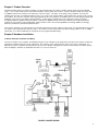
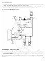
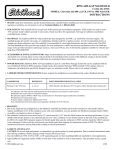
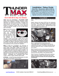
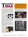
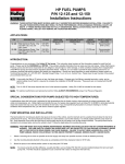
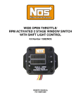
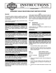
LAUNCHER PROGRESSIVE NITROUS CONTROLLER
P/N’s 15975NOS, 15976NOS, 15977NOS and Upgrade Kits
INSTALLATION AND OPERATION INSTRUCTIONS
199R10466
CONGRATULATIONS on purchasing your NOS Launcher Progressive controller! Your system is composed of the highest quality
components available. It should provide many miles of trouble-free performance when used correctly. If you have any questions regarding
the performance of your system, call NOS Technical Service at 1-866-GOHOLLEY.
NOTICE: Installation of Nitrous Oxide Systems Inc. products signifies that you have read this document and have agreed to the
terms stated within.
It is the purchaser’s responsibility to follow all installation instruction guidelines and safety procedures supplied with the product as it is
received by the purchaser to determine the compatibility of the product with the vehicle or the device the purchaser intends to install the
product on.
Nitrous Oxide Systems Inc. assumes no responsibility for damages occurring from accident, misuse, abuse, improper installation, improper
operation, lack of reasonable care, or all previously stated reasons resulting from incompatibility with other manufacturers’ products.
Nitrous Oxide Systems Inc. assumes no responsibility or liability for damages incurred by the use of products manufactured or sold by
Nitrous Oxide Systems Inc. on vehicles used for competition or racing.
Nitrous Oxide Systems Inc. neither recommends nor condones the use of products manufactured or sold by Nitrous Oxide Systems Inc. on
vehicles, which may be driven on public roads or highways, and assumes no responsibility for damages incurred by such use.
NOS nitrous oxide is legal for use in most states when used in accordance with state and local traffic laws. NOS does not recommend or
condone the use of its products in illegal racing activities.
NOS has not pursued California Air Research Board (CARB) exemptions for these kits, hence, they are not legal for use on pollutioncontrolled vehicles in California. A correctly installed NOS nitrous system should not alter the emission control performance of your vehicle
under standard EPA test cycle conditions.
HAZARDS DEFINED
This manual presents step-by-step instructions that describe the process of installing your NOS Launcher Progressive Nitrous Controller.
These procedures provide a framework for installation and operation of this kit. Within the instructions, you are advised of potential
hazards, pitfalls, and problems to avoid. The following examples explain the various hazard levels:
WARNING! Failure to comply with instructions may result in injury or death.
CAUTION! Failure to comply with instructions may result in damage to equipment.
NOTE: This information is important, needs to be emphasized, and is set apart from the rest of the text.
HINT: These special instructions provide a handy work tip.
NITROUS OXIDE INJECTION SYSTEM SAFETY TIPS
WARNINGS
IT IS NOT LEGAL TO ENGAGE NITROUS OXIDE INJECTION SYSTEMS ON PUBLIC ROADS OR HIGHWAYS. NITROUS OXIDE
INJECTION SYSTEMS ARE ONLY TO BE ENGAGED DURING SANCTIONED COMPETITION OR RACING EVENTS.
Do not attempt to start the engine if the nitrous has been injected while the engine was not running. Disable the ignition system
(consult owner’s manual) and crank the engine with the throttle wide open for several revolutions before attempting to start.
Failure to do so can result in extreme engine damage.
Never permit oil, grease, or any other readily combustible substances to come in contact with bottles, valves, solenoids, hoses,
and fittings. Oil and certain gases (such as oxygen and nitrous oxide) may combine to produce a highly flammable condition.
Never interchange nitrous and fuel solenoids. Failure to follow these simple instructions can result in extreme engine damage
and/or personal injury.
Never drop or violently strike the bottle. Doing so may result in an explosive bottle failure.
Never change pressure settings of safety relief valve on the nitrous bottle valve. Increasing the safety relief valve pressure
settings may create an explosive bottle hazard.
Please note that the NOS bottle label has changed to a two-part assembly. The first label is already located on the bottle. Upon
filling your bottle with nitrous oxide, apply the (second) material information label in the area indicated in the picture to the right.
NOTE: The material information decal is located in the same plastic bag as the bottle.
WARNING! Once the nitrous bottle has been filled, it must be shipped according to the applicable transportation and shipping
regulations!
Do not deface or remove any markings, which are used for content identification.
Nitrous bottle valves should always be closed when the system is not being used.
Notify the supplier of any condition that may have permitted any foreign matter to enter the valve or bottle.
Keep the valves closed on all empty bottles to prevent accidental contamination.
When storing a nitrous bottle, make sure the outlet is capped with a plug so that contaminants don’t get into the fittings.
It is important that all threads on the valves and solenoids are properly mated.
Never force connections that do not fit properly.
2
TABLE OF CONTENTS
Chapter 1 Product Overview ................................................................................................... .4
Chapter 2 Hardware Installation .............................................................................................. 4
2.1 Master Controller Installation and Wiring ..............................................................................................................................4
2.2 Hand-Held Controller and Touchscreen Wiring ....................................................................................................................5
2.3 Slave Controller Wiring .........................................................................................................................................................6
2.4 Wide Band Oxygen Controller Installation and Wiring ..........................................................................................................6
2.5 NOSbus Wiring .....................................................................................................................................................................7
Chapter 3 System Communications………………………………………………………………...8
3.1 System Communications ......................................................................................................................................................8
Chapter 4 PC/Laptop and Touch Screen LCD Software and System Use Overview
..................................................................................................................................................... 8
4.1 Software Installation ..............................................................................................................................................................8
4.2 Software Overview................................................................................................................................................................8
Chapter 5 Touch Screen LCD Function ................................................................................ 14
5.1 Touch Screen LCD Function and Overview........................................................................................................................14
Chapter 6 Hand Held Controller Operation ........................................................................... 16
6.1 Hand Held Controller Operation and Function....................................................................................................................16
Chapter 7 System Operation and Testing ............................................................................. 17
7.1 Initial Testing and Verification.............................................................................................................................................17
Launcher Accessories and Upgrades .................................................................................... 18
3
Chapter 1 Product Overview
The NOS Launcher Progressive Nitrous Controller is a fully featured progressive nitrous controller offering control of up to 4 individual
stages . These features make this the most advanced nitrous control system on the market. A master controller controls two stages and
an additional add-on slave controller can control up to two more stages. All stages can be progressively controlled. The Launcher
controller can also ”talk” to a wide band oxygen sensor. The sensor can be used to shut the system down in the event of a lean or overlyrich condition. The Launcher controller can be fully programmed either via a laptop or an available touchscreen LCD display (a laptop with
USB ports or the touch screen LCD is required for tuning). Certain changes typically done in the staging lanes at the track can be
accomplished with an available hand-held controller. A SD (Secure Digital) memory card reader is built-in on the LCD and hand-held
controller to store programs and for datalogging. Add on modules can be connected using NOSbus technology, NOSbus technology
allows the controllers to communicate with each other.
The Launcher controllers can control progressive solenoid operation based on time, RPM, or engine boost. The programmable nitrous and
fuel ramps can be programmed in any curve shape. The Launcher can be activated based on various voltage inputs as such as a WOT
switch, TPS, etc, as well as RPM and can shut nitrous off at a programmed RPM ceiling.
Chapter 2 Hardware Installation
2.1 Master Controller Installation and Wiring
The master controller, slave controller, and wideband oxygen sensor controller are all designed and constructed in a manner to endure the
typical harsh conditions found in a racing environment. The controllers can be mounted in the engine or passenger comparment. It is
advisable to keep the controllers away from direct heat and severe vibration. Although not required, it is beneficial to use rubber isolators
when mounting the controllers on applications that may see severe tire shake, etc.
FIGURE 1 MASTER WIRING
4
1.
Before mounting the master or slave controller, write down the ID number for them. This number is located on the back of the
unit. It is the upper right-hand number and is indicated by ID#. Find a suitable mounting place for the main controller. Mount it
securely.
2.
Install the 12 ga. black ground cable to a good chassis ground that is ground securely to the engine as well.
3.
Connect the main 8 pin connector to the controller.
4.
Connect the white wire to a +12v fused switched power source. You should install this to a circuit that has a 5A fuse and can
supply two amps to the unit. If this is not available you should install a fuse holder.
5.
Connect the black 18 ga. wire in the 8 pin connector to a good chassis ground.
6.
Connect the green wire to the RPM pickup point. You will define the proper RPM conversion in the software setup. This wire can
go to the typical “tach out” output found on most ignition boxes and some distributors (12v square wave). For DIS equipped
vehicles it can be connected to one of the individual coil signal wires which is typically a ground trigger. For specific applications
consult a factory service manual.
7.
The White/Blue wire is the “Input 1” wire. This is the trigger wire for the system. Connect to either a 12v or ground microswitch
input or it can be connected to the signal output wire on a TPS with either a rising or falling voltage. The signal type is selected in
the software configuration. If you are not sure which wire this is, consult a factory service manual.
8.
The White/Red wire is the “Input 2” wire. It can be used to activate additional stages or disable a stage. Connect to either a 12v
or ground microswitch input or it can be connected to the signal output wire on a TPS with either a rising or falling voltage. If this
wire will not be used, heat shrink the end and secure it tightly out of the way. See section 4.2 in the software on more information
regarding how to active multiple stages.
9.
The Yellow and Orange wires are General Purpose Outputs (GPO’s) that are programmable in the software for various purposes
such as activating a timing retard, etc. These are low current ground outputs. If using to trigger a high current device (over 1
Amp), use them to trigger a relay. If you need a +12v output trigger, use this ground GPO to trigger a relay that will supply +12v.
If these wires will not be used, heat shrink the end and secure it tightly out of the way.
10. The 12 ga Blue and Red wires are the solenoid ground outputs. The system works by providing a ground to the solenoids.
These wires are to be connected directly to the solenoids. Power must be supplied separately to the solenoids by utilizing an
appropriate relay. See figure 1.
11. The three pin connector on the main controller is for an optional nitrous pressure sensor input (PN 15661NOS). This kit includes
the pressure sensor transducer and cable. Install the sensor at the bottle and plug in the harness.
12. The four pin connector is for the USB communications cable. This cable is connected to the laptop computer in order to
communicate.
13. The vacuum line from the controller is to be used if progressive nitrous control based on engine boost is desired. It needs to be
connected to a full manifold vacuum source. It can also be connected to intake manifold vacuum/boost or crankcase vacuum just
for datalogging purposes as well.
14. The orange twisted pair cable coming from the unit is the NOSbus cable. This is the communications cable that the controller
uses to communicate with other devices such as an additional slave controller, wide band oxygen sensor controller, as well as the
hand held and touch screen LCD controllers. NOSbus devices are connected in a serial manner. The short terminator jumper
harness must be connected to the master controller first (short orange wires with a blue lock tab). Orange jumper harnesses are
connected between all the NOSbus devices. The last unit in series must have the NOSbus line capped with a terminator plug.
This is a single plug with a blue lock tab. See section 2.5.
2.2 Hand-Held Controller and Touch Screen LCD Wiring Installation
1.
If the Hand-Held Controller or Touch Screen LCD is used, it should be installed and wired at this time. These units have a power and
ground wire as well as NOSbus connection. Connect the white power wire to a fused switched 12 volt power source. Connect the
black (ground) wire to a good chassis ground. See figure 1. The optional toggle switch can be installed if the user wishes to not have
the LCD and/or main controller powered at all times.
2.
Connect the orange NOSbus wires to the master controller. See section 2.5.
3.
The units should now be recognized and ready for use.
5
2.3 Slave Controller Installation
1.
If the optional slave controller is being used (PN 15978NOS), install it now. The slave controller offers an additional 2 stages of nitrous
capability. Fasten the unit in the same manner that that master controller is installed.
2.
The slave unit wiring and colors are the same as the master controller. The slave unit does not have the USB cable connector,
manifold vacuum/pressure input, or fuel pressure sensor input. Wire it per section 2.1 above. See Figure 2 below.
3.
Connect the orange NOSbus wires. See section 2.5.
FIGURE 2 SLAVE WIRING
2.4 Wide Band Oxygen Sensor Controller Installation
1.
If the optional wide band oxygen sensor controller is being used (PN 15979NOS, requires sensor sold separately, PN 534-194 for NTK
sensor or PN 534-198 for Bosch LSU4, NTK recommended for leaded fuels) mount it now. The controller has a brown wire loop on it.
If the Bosch sensor is being used, this wire MUST be cut. Cut the wire and place heat shrink over both cut ends. If the NTK sensor is
being used, do not cut the wire.
NOTE: Make sure the brown wire loop is cut if using a Bosch sensor. If the wire loop is not appropriate for the sensor, damage
can result.
6
2.
This kit comes with a 5 foot harness to power the controller. The wire colors are black and red. Connect the black wire to a clean,
sound chassis ground. The red wire must be connected to a switched +12v power source capable of supplying at least 5 Amps.
NOTE: The wide band controller MUST be wired so that it is powered on whenever the engine is running, whether or not the
Launcher is being used. If the controller and sensor are not powered when the engine is running, the sensor will be damaged.
3.
Connect the orange NOSbus wires. See section 2.5.
2.5 NOSbus Wiring
Any device that has orange wires has NOSbus communications. This includes the master controller, slave controller, wideband O2
controller, LCD controller, hand held controller, and others. These items must be connected properly to communicate.
1. The following pictures indicate how to connect these devices. For proper communications, the short terminator jumper harness
must be used at the master controller (or end device, the master controller can be in the middle of the chain). At the end of the
devices, the terminator plug must be installed.
7
Chapter 3 System Communications
3.1 System Communications
Depending on what hardware is used, there are a few different scenario’s regarding what device maintains the main configuration file.
These scenario’s are:
1)
System with a Master Controller and Laptop Computer Only – When using only the master controller and a laptop, the master
controller will store the particular configuration file that is being used. This file can be downloaded from the master controller to
the laptop to be used. A new file can be created and saved on the laptop. This file can then be uploaded to the master controller
where it will be the configuration file that drives the system.
2)
System with a Master Controller and LCD or Hand Held Controller – When the hand held or LCD controllers are used, these
devices become the primary holder of the configuration file. Whatever file is resident in the hand held or LCD is automatically
pushed into the master controller and overwrites whatever file might have been on the master controller. Files can be loaded and
saved via the SD Memory card.
3)
System with a Master Controller and LCD or Hand Held Controller with Laptop connected via USB into LCD or Hand Held – The
laptop can be connected via USB into the LCD or Hand Held. Do not connect the laptop directly into the master controller if the
LCD or Hand Held Controllers are being used. This configuration “works” the same as a combination of #1 and #2 above. Files
can be downloaded or uploaded to and from the LCD or Hand Held via the laptop. These files are then pushed automatically into
the master controller.
Chapter 4 PC/Laptop and Touch Screen LCD Software and System Use Overview
NOTE: The following software information is specific when using a laptop only. However, the general settings and other areas are the
same on the touch screen LCD. This section is used when referencing tuning using the touch screen. Touch screen specifics are covered
in section 5.1.
4.1 Software Installation
Software is compatible with Windows 2000, ME, XP, and Vista.
Using the included CD, install the Launcher software in your laptop computer. The file is self executing.
4.2 Software Overview
There are two kinds of files that this system uses. They are Nitrous Configuration Files which have a .nos filename extension and Nitrous
Datalog files which have a .noslog or .log filename extension. The Nitrous Configuation File are the actual “tuneup” files that dictate the
operation of the system. The Nitrous Datalog files are made each time a run is datalogged.
Nitrous Configuration File Creation
To create a new file you go to “file” and “new”. This will open a new file. Go to “File” and “Save As” to save it to any directory and new
name. Created files can be opened by going to “File” and “Open”.
Communicating with the Laptop and Controller
To communicate with the controller, connect the USB cable to the controller and to a USB port on the laptop. When the cable is connected
and the unit powered, the icon in the top middle of the screen should say “Connected”. If communcation is not present, it will say
“Disconnected”.
8
IMPORTANT NOTE: In order for proper communication, the file that is in the controller must have the proper “Master Serial Number”
entered. See section “General Settings”. The master serial number is located on the back of the controller. You must first create a file that
has the proper master number and Upload that file before you can actually have connection. See Uploading/Downloading (next section).
Uploading/Downloading files to and from the controller and Laptop
To send a new Configuration File to the controller, first open a file on the laptop. Then with the unit powered and USB cable connected, hit
the “Upload” Icon at the top left. This will send the file to the controller. You should get a verification message. To retrieve and view a
file that is already in the controller, hit the “Download” Icon at the top left. Initially, there will no files to download. A new file must be
created and saved.
NOTE: In order to “Download” a file from the controller, there must be a configuration file already open, or the software won’t
give you the option of downloading. If a file is not open, simply go to “File” and “New”. Then “Download” the file.
GENERAL SETTINGS
GENERAL SETTINGS
NOTE: This section overviews all of the controller functions. They are the same in the PC software as well as the Touch Screen
LCD. Use this section for either device.
General
Master Serial Number – This number must be entered for the laptop to see the controller. This number is printed on the back of the
controller. Example – 31
Slave Serial Number – This number must be entered if using a slave controller. If no slave is used, enter 0
RPM Multiplier – Number is dependent on the tach wire pickup location. This number is used to convert the number of inputs per
revolution to proper montoring RPM. For a typical tach out on an MSD box use ÷4 for a V8 engine. If the engine has a distributorless
ignition system (DIS) you will most likely have to enter a x4 or x8 depending on if the igntition is a waste fire setup or not. If not certain,
simply pick a number and note what the Launcher is reading and compare it to the actual engine speed at idle. If they do not match pick a
different number until they do. For example, if you pick x8 and the Launcher is showing an RPM reading two times higher, than selecting
x4 should correct the reading.
9
IMPORTANT NOTE: Make sure you verify that the controller is showing the correct engine RPM or the system will not operate
correct and engine damage or failure may result. Go to the “Monitor” screen when the engine is running to make sure the
monitor shows actual engine RPM. See “Monitor Screen” section.
AFR – If wide band O2 input is used, the unit can automatically disable nitrous operation if the A/F is too lean or too rich. The “cutoff delay”
is the time that the unit will wait until it looks for this A/F ratio. In other words, if you enter .5 seconds, the unit will wait .5 seconds after
activation before it will truly turn the system off due to the target lean condition. This allows the sytsem to ignore the quick lean spike that
typically occurs with the initial “hit”.
INPUTS
If using two stages, you can use either one or two inputs to activate each stage or stages. Input 1 or 2 can activate both stages 1 and
stage 2 or input 1 and 2 can be used to individually activate stages 1 and 2.
Input #1 – Select from “Disabled”, “ TPS Rising”, “TPS Falling”, “12 v Switch”, or “Ground Switch”. The last two would be a constant 12v or
ground such as from a microswitch. If a TPS is used, select the voltage that activation will occur at. Make sure you know whether your
TPS has a rising (0-5v) or falling (5-0v) voltage pattern. EXAMPLE?
Input #2 – Select from “Disabled”, “ TPS Rising”, “TPS Falling”, “12 v Switch”, or “Ground Switch”. The last two would be a constant 12v or
ground such as from a microswitch. If a TPS is used, select the voltage that activation will occur at. Make sure you know whether your
TPS has a rising (0-5v) or falling (5-0v) voltage pattern.
Master Stage 1
MASTER STAGE 1
Present – “click” box if using stage 1
Pause Enabled – “click” box for pause enabled. If selected, when nitrous is activated, and the driver has to lift off the throttle causing the
system to deactivate momentarily, and then gets back on the throttle, the system will resume the “ramp” in the same spot when
it was deactivated. If this is not enabled, the nitrous/fuel ramp will start at the beginning if this occurs.
First Gear Lockout – This is a method that can allow for the system to not be engaged in low gear. It operates only when the driver hits
the RPM Nitrous Cutoff point. After this occurs, the system will activate as programmed. If the RPM Nitrous Cutoff point is not
hit at all, the system will not turn on. As an example, set the nitrous RPM cutoff point to 6800 RPM. The driver needs to shift at
10
6900+ RPM in low gear. When the 1-2 gear change is made, the system will then activate as programmed from that point on.
In other words the controller must see 6800 RPM 1 time before it will activate the system.
Input #1 Will – Select “Be Ignored By”, “Enable”, or “Disable” for this stage for Input #1
Input #2 Will - Select “Be Ignored By”, “Enable”, or “Disable” for this stage for Input #2
Strategy Type – Select from “Time Based”, “RPM Based”, “MAP Based”, or “Purge”.
Time Based – Allows user to program nitrous/fuel percentage vs. time
RPM Based – Allows user to program nitrous/fuel percentage vs. engine RPM
MAP Based – Allows user to program nitrous/fuel percentage vs engine manifold pressure. This would typically be used with a
turbocharged application. This can be used to spool the turbo on the starting line.
Purge – Allows user to program as a “progressive purge” function
Map Nitrous Cutoff – Automatically shuts the system off at a programmed boost pressure. Set to “20” if not using.
NOTE: MAKE SURE THIS IS SET TO 20, if set to 0, the system may deactivate at WOT as it will sense 0 as atmospheric, WOT
pressure!! 20 is not a “special” number, just a higher number so it won’t deactivate due to atmospheric pressure. If truly using
for a boost shutoff, enter the intended number.
RPM Nitrous Cutoff – Automatically shuts the system off at a programmed RPM. Same function as the upper limit of a window switch.
Start % - Allows for the start percentage to be typed in.
Final % - Allows for the end percentage to be typed in.
Frequency – Frequency the solenoids will be pulsed at. 15-22 Hz is the typical range. NOS recommends 20 Hz for their solenoids.
RPM Trigger – RPM at which the system will activate at. Same as the lower limit on a window switch.
Delay – (Time based only) Time delay that can be added after system is triggered for activation. This is used for fine tuning or delayed
activation of a second stage when the same input is used.
Ramp Time - (Time based only) Ramp time from activation to final %
RPM End – (RPM based only) End RPM for final nitrous/fuel %. At RPM higher than this, % stays the same.
MAP Trigger - (MAP based only) Manifold Pressure that activates ramp.
MAP End - (MAP based only) End Manifold pressure for final nitrous/fuel %. At RPM higher than this, % stays the same.
Graph Features
“Reset to Straight Line” – Will create a linear, straight line between the Start % and Final %
“Smooth Points” – Each time this is hit, it performs a smoothing function to the curve.
“Undo” – Undoes the last smoothing function
“Smooth When Dragging” – Will “pull” and smooth surrounding points when modifying the curve.
Master Stage 2
Operates the same as “Master Stage 1” above except this operates a second stage. Be aware that you can use input 1 to trigger both
stages and delay Stage 2 using the “Delay” time. This eliminates the need for any separate delay timers.
11
Master GPO
MASTER GPO
GPO = General Purpose Outputs
GPO’s are low current ground outputs (1 Amp max) that the user programs to occur based on selectable variable. They can trigger items
such as ignition retards, water injection, etc. If the device is over 1 Amp, use the GPO to trigger a relay. If you need a +12v
trigger, use this ground output to activate a relay with a +12v output.
To have an output occur when a particular stage of nitrous is activated, select “Turn on based on nitrous %” If you select 0%, it will activate
as soon as the nitrous is triggered. Setting it to a higher percent will delay activation of that GPO until that nitrous percentage is met.
12
MONITOR SCREEN
The monitor screen (below) is opened by clicking on the “monitor” tab. When the controller is powered, you can see (if
connected) Engine RPM (view this to make sure you have the proper RPM Multiplier selected), Input Trigger information, wide
band A/F, nitrous pressure, MAP reading, and monitor the status of all nitrous stages. You can watch them operate on the slide
bar.
MONITOR SCREEN
DATA LOGGING
Recording Data
To record data, simply push the “Logging Off” Icon at the top. It should change to “Logging On” and automatically record data.
Hit it again to stop logging. A log file will be automatically named with the following nomenclature: Date-Time. For example
20070315-130035 = March 15, 2007 1:00:35
There are two ways to view data which are “Playback Mode” and Graphical Analysis.
To view a log file that was just saved, go to “File” and you should see the last saved file listed. Click on it once and it will appear
and look like the monitor screen, except the “Play”, “Stop”, and other buttons will appear active at the top of the screen. This is
helpful to view what is occurring. You can make sure that the various stages are arming and operating properly.
Files will be stored to the following directory: C:\Program Files\NOS\Launcher. Files can be moved from that location afterwards if
desired.
To view the data graphically, have the log file open and hit the “Analysis” button which should be active. This will bring up a
graph as shown below. To add a graph line for a particular channel, click in the box next to the channel you’d like, and if that
data was logged, it will appear on the graph. You can take the mouse cursor and put it on a line on the graph. It should turn
into a “hand”. Click and cursor will appear on that line. You can then use the arrow keys to move forward and backward on the
data. Values for each channel will appear at the top for all channels. You can also zoom into data on the graph. Click and hold
the left button and scroll the mouse around an area to zoom into it.
13
DATA LOG GRAPH
Chapter 5 Touch Screen LCD Operation
5.1 Touch Screen LCD Operation and Function
The Touch Screen LCD can basically do everything that a laptop computer can do. The only real difference is that there is better visibility
of a complete datalog trace on a laptop computer. The LCD allows viewing of datalogs, but due to the smaller screen size, the data must
be viewed in separate screens if the file size is very large. If the LCD is used, all functions of the controller can be programmed without a
laptop computer.
Because of this, the touch screen can be permanently mounted in a vehicle, and be used to control all functions of the Launcher. A stylus
is included that can safely be used to “touch” the screen.
The following icons appear on the main screen. Their functions are described below.
Launcher – Provides all the functions for the Launcher Controller (described in more detail below)
Setup – Offers the following functions:
Update FW - Used to update firmware. Newer LCD firmware can be loaded on the SD card and loaded via this method.
Files – Allows files to be deleted from the SD card
Brightness – Allows for the LCD brightness to be dimmed or brightened
Slide Show – Allows for a generic slide show to be viewed. You can put your own images on the SD card and they can be displayed on the
LCD. Images must be a 24 bit, 320 x 240 pixel .bmp format, or they will not be recognized.
Help Menu - Offers information for technical assistance
About Menu – Shows firmware versions for the LCD display
14
Launcher Functions – The following overviews the Launcher Functions
Configure – Allows for all programming of the actual nitrous controller. Programs all functions for the 1-4 stages of nitrous that can be
controlled. A full overview of this follows below.
Purge – If a stage has been configured as a purge function, this icon can be pressed to activate the purge, rather than hard-wiring a button.
Monitor – Shows a “gauge panel” showing engine RPM, A/F ratio, Nitrous pressure, MAP pressure, and the status of each stage. There
are four indicators showing Armed/Active/RPM/Map. When the trigger input is set, the “Armed” will show a green indicator. When the
system is activated, the “Active” will show a green indicator. If the high side RPM cutoff is reached, the “RPM” indicator will turn red. If the
“Map” pressure cutoff point is reached, the indicator will turn red. If any indicator is red, the unit will not activate the nitrous. Also shown
are rich/lean cutoff indicators on the monitor.
Logging – Allows for logging of data to an SD card. This data can then be reviewed on the LCD or a computer. The user must hit the
“start” and “stop” to start and stop logging. An SD card must be inserted to capture the data to.
Controller Information (CtlrInfo) – Shows the firmware version of the controller and other devices.
Analysis – Allows for a datalog to be selected from a SD card and viewed. You will be asked to select a log file from the SD card. After
selecting the file, the file will be shown on the screen. About 4 seconds of data is shown at one time on the screen. Use the forward and
backward arrow buttons (double arrows) to move back and forth between screens. The →│ and │← buttons will take you to the beginning
and end of the data. In order to not clutter the screen, all of the data (RPM, A/F ratio, trigger, etc) is not shown all at one time. It can be
viewed separately (for the same time period) by hitting the “style” button on the bottom of the screen. At the top of the screen, whatever
data shown is indicated. Data is differentiated by color as shown.
Help Menu – Offers information for technical assistance.
Launcher Configuring
The following takes you through the “Configure” portion with the LCD.
The first function that shows up are files on the SD card. You can select one of them and then load it to the LCD display which will
automatically download it to the controller. If you don’t want to download a file, but just modify the current program, select the “X”. If there
are no setup files which will initially be the case on a new unit, select the “X”.
The following options are the same on the LCD as they are in the PC software. These options are described in detail in section 4.2.
Please review this section to understand these options.
The following buttons are available on most screens:
EXIT – Exits out of the configuration
Next – Moves to the next configuration screen
Prev – Moves back to the previous screen
GoTo – Allows quick movement to other areas without having to move through all the screens
Areas that are “active” in the touch screen are typically “white boxes” and white “check boxes”. Touching them will either show available
selection options or activate that feature. There may be arrow keys that allow you to view options. Numerical values can be adjusted with
+ and – keys.
The following is additional information that is different on the LCD than the PC software:
“Set Linear” – The “Set Linear” can be used when defining the nitrous ramp to quickly enter a linear ramp. First enter the start and final
percentages, then select the “Set Linear” button. This will create a linear ramp between the start and final percentages.
Once the initial ramp is made, it can be modified in the following ways:
-
“Smooth” – used to smooth the curve
Grab individual points (same as with the PC software) and drag them individually
The second graph for a stage is similar to the first, except that it automatically moves through each point, making it easier to
move an exact location
15
Chapter 6 Hand Held Controller Operation
6.1 Hand Held Controller Operation and Function
The Hand Held Programmer is designed as an aid for programming when the laptop can not be used in a vehicle (laptops are not
allowed in vehicles by many racing sanctioning bodies as well as you usually don’t want a laptop inside a fast race car). It can not create
or modify configuration files, but can do the following:
-
Allows you load a configuration file from the SD card. This is useful when making a final tune-up decision in the staging lanes
from pre-programmed configuration files
Allows you to datalog a pass to the SD card and view it later on the laptop or PC
Allows you to monitor the following:
- Engine RPM and MAP Reading
- Nitrous Pressure
- Trigger 1 and Trigger 2 voltages
- # AFR Channels
- Air/Fuel Ratio’s
- % Nitrous Activation for each Channel
When the handheld is first opened, it will show the status of the system as indicated by the word “STATUS”. There are 8 digits below that
indicate the following:
The first two letters shown indicate the status Input Trigger #1 and #2. These first two letters could be any of the following:
T
t
.
=
=
=
Trigger enabled and currently triggered
Trigger enabled but not currently triggered
Trigger disabled
The third and fourth letters indicate the status of a lean or rich shutoff. These letters could be any of the following:
L
l
.
R
r
=
=
=
=
=
Lean cutoff just occurred (which shut the nitrous activation off)
Lean cutoff enabled, but not activated
Lean or Rich cutoff not enabled
Rich cutoff just occurred (which shut the nitrous activation off)
Rich cutoff enabled, but not activated
The last four letters reference nitrous stages 1 though 4. These letters could be any of the following:
A =
Stage is enabled and is active (All conditions met for activation and solenoid is being triggered)
a =
Stage is enabled, currently armed, but not active (Input trigger is met, but system is not active due to time or RPM
so solenoid is not being triggered)
- =
Stage is enabled, but not armed or active
. =
Stage is not enabled
conditions
Two Examples:
T . l . A a . . This example means that trigger #1 (TPS or microswitch) is enabled and triggered (T), Trigger #2 is disabled(.), there is a lean
cutoff enabled, but not active (l), there is no rich cutoff enabled (.), Stage #1 is enabled and activated (A), stage #2 is enabled and armed,
but not active (a), and stages #3 and #4 are not enabled (. .)
T t . r A A - - This example means that both trigger #1 is enabled and triggered (T), Trigger #2 is enabled, but not activated (t), there is no
lean cutoff enabled (.), there is a rich cutoff enabled, but not activated (r), Stages #1 and #2 are enabled and activated (A A), and stages 3
and 4 are enabled, but not armed or activated (- -)
Navigation
The following instructions are how to navigate through the functions the hand-held offers.
Starting with the main STATUS SCREEN you can perform the following…
Select “↓MENU” – This brings up the monitoring . After this is selected, hit the “Next” and “Prev” buttons to scroll through the following:
- Ramp Percentage Levels for each stage
- Engine RPM and MAP reading
- Nitrous Pressure
- Trigger 1 and Trigger 2 voltages
16
- # AFR Channels
- Air/Fuel Ratio’s
Select “Next” and “Prev” - This scrolls between CONFIG (configuration files), LOGGING (data log files) and SETUP (changes contrast).
The following describes how to operate these choices:
1) CONFIG – Will load a configuration file off the SD card. Press the SELECT button. This will show the number of files on the SD card.
Use the NEXT and PREV buttons to scroll through them. To load any of these files hit the SELECT button. It will load that configuration
file and indicate “sending” and “success”. The config files must be loaded onto the SD card via a laptop or PC.
2) LOGGING – This is used to perform a datalog. Hit the SELECT button. This will start the datalog (it will take a couple of seconds to
start). Then hit the SELECT button to stop. The file is logged to the SD card and can be viewed on a PC or the LCD.
3) SETUP – Hit the SELECT button. This will bring up the contrast which can be changed by using the NEXT and PREV buttons.
4) STATUS – Brings up the monitoring described above. Use the “Next” and “Prev” buttons to view.
5) PURGE – Allows you to purge if a stage is set up as a purge. Hit the SELECT button to purge.
Chapter 7 System Operation and Testing
7.1 Initial Testing and Verification
NOTE: Make sure that all testing is performed in a safe and controlled environment such as at the race track.
It is highly recommended that all features and functions are verified for proper operation before nitrous oxide is actually introduced into the
engine. During all of this testing, it is recommended that the nitrous bottle is left closed/unhooked. This will prevent nitrous from being
introduced into the engine by accident if the configuration is incorrectly set up. Part of this testing will require that the fuel solenoid be
activated. To prevent excess fuel from entering the engine, it is recommended that the fuel inlet supply, to the solenoid, be blocked off.
Excess fuel entering the engine, while not running, may cause a hydro-lock condition. This may result in internal engine damage.
First, ensure that proper engine speed and trigger inputs are occurring. Do this by viewing the monitor screen. With the engine running,
ensure that the engine speed shown on the monitor matches the actual engine speed of the engine as verified by a tachometer, etc. Next
verify that the defined and wired triggers are activating as programmed. This is shown at the top of the screen (Trigger #1, Trigger #2 if
used).
If the wideband A/F ratio sensor is connected, make sure that it is showing a proper reading when the engine is running (should show 1215:1 A/F at idle for most engine). It will take a couple of minutes for the sensor to heat up after the engine starts before it will report the A/F
ratio.
Once the information above is verified, it is then recommended to make a “dry run” of the system. This should be done with the nitrous
disconnected as well as the fuel supply. To do this, shut off the nitrous bottle. To disarm the fuel, remove power to the solenoid. Power
can be removed from the nitrous solenoid as well. If at a race track, then make a pass while logging data. After the pass, review the data.
The monitor screen can be used to review that the various stages of nitrous are activating and deactivating as they should. The Analysis
screen will show this as well.
Once a dry run is performed, the system can be activated with the nitrous and fuel solenoids hooked up. The following are some basic
guidelines for tuning. Every engine will be slightly different:
-
Nitrous typically should not be activated below 3000 RPM or possibly higher depending on the engine. If activated below
3000 RPM, use the progressive controller to meter less amounts of nitrous/fuel as to not create excessive cylinder pressure
causing detonation.
Nitrous should only be activated at wide open throttle (WOT)
If using a wideband A/F sensor, use the lean cutoff feature. A delay of approximately .5 seconds should be past the typical
lean spikes seen from nitrous activation. The leanest it is recommended to run an engine at with nitrous would be between a
12-12.5:1 A/F ratio. A/F ratio’s in the 11’s are typical with nitrous when trying to get a safe tune.
Use the RPM cutoff to help shut the nitrous off when using a manual transmission.
On race engines that use a vacuum pump and sealed crankcase, connect the vacuum port to the crankcase. This can be
used to monitor the vacuum and detect any detonation by showing vacuum fluctuations in the crankcase.
17
Launcher Accessories and Upgrades
The following are Part Numbers for Launcher Systems and upgrades.
15975NOS
15976NOS
15977NOS
15978NOS
15979NOS
534-194
534-198
15980NOS
15981NOS
15661NOS
15662NOS
15663NOS
15664NOS
15665NOS
15666NOS
15667NOS
Launcher with LCD Display
Launcher with Handheld Display
Launcher Nitrous Controller
rd
th
Launcher Slave Controller (adds 3 and 4 stages progressively controlled), includes NOSbus cable
Launcher Wide Band (Controller only, requires sensor below, allows datalogging of A/F and rich/lean cutoff)
includes NOSBUS cable
NTK Wide Band Oxygen Sensor (recommended for leaded fuels)
Bosch LSU4 Oxygen Sensor
Launcher, Hand held Upgrade – Includes Hand held controller and NOSbus cable
Launcher, LCD Upgrade – Includes LCD and NOSbus cable
Launcher, Nitrous Pressure Sensor Upgrade (Includes transducer and cable)
Launcher, 6 FT USB PC Communications Cable
Launcher, NOSbus Cable, 1 FT
Launcher, NOSbus Cable, 12 FT
Launcher, NOSbus Cable, 4 FT
Launcher, NOSbus Cable, 8 FT
Launcher, NOSbus Terminator Kit
NOS Technical Support
Toll-Free Phone: 1-866-GOHOLLEY
Phone: 1-270-781-9741
Fax: 1-270-781-9772
For online help, please refer to the Tech Service section of our website: www.holley.com
For bottle refill information: 1-800-99-REFILL
199R10466
Date: 08-7-07
18