1
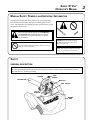
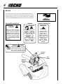
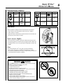
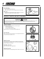
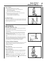
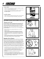
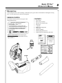
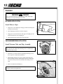
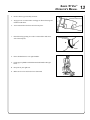
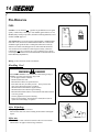
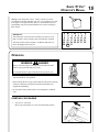
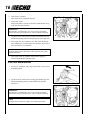
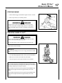
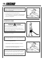
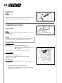
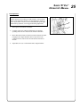
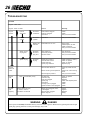
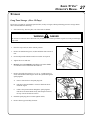
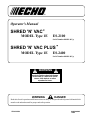
Operator's Manual
SHRED 'N' VAC®
MODEL Type 1E
ES-2100
Serial Number 001001 & Up
SHRED 'N' VAC PLUS™
MODEL Type 1E
ES-2400
Serial Number 001001 & Up
WARNING
The engine exhaust from this
product contains chemicals known
to the State of California to cause
cancer, birth defects or other
reproductive harm.
WARNING
DANGER
Read rules for safe operation and all instructions carefully. ECHO provides this Operator's Manual which
must be read and understood for proper and safe operation.
X7501135201
89861009662
10/99
2
INTRODUCTION
Welcome to the ECHO family. This ECHO product was designed and manufactured to provide long life and on-the-jobdependability. Read and understand this manual. You will find it easy to use and full of helpful operating tips and
SAFETY messages.
THE OPERATOR'S MANUAL
Read and understand this manual before operation. Keep it in a safe
place for future reference. It contains specifications and information for
operation, starting, stopping, maintenance, storage and assembly
specific to this product.
TABLE OF CONTENTS
Introduction ............................................................... 2
- The Operator's Manual ....................................... 2
Manual Safety Symbols and Important Information .. 3
Safety ......................................................................... 3
- General Description ............................................ 3
- Decals ................................................................. 4
- International Symbols ......................................... 5
- Equipment ........................................................... 5
- Fuel ..................................................................... 5
- Personal Condition and Safety Equipment ......... 6
- Safe Operation .................................................... 7
- Extended Operation/Extreme Conditions ............ 8
Description ................................................................ 9
- Emission Control ................................................. 9
- Contents ............................................................. 9
- ES-2100/2400 Major Components ..................... 10
Specifications ........................................................... 11
Assembly ................................................................. 12
- Blower Application ........................................... 12
- Vacuum/Shredding Application ....................... 12
Pre-Operation ........................................................... 14
- Fuel ................................................................... 14
Operation ................................................................. 15
- Starting Cold Engine ......................................... 15
- Starting Warm Engine ....................................... 16
Copyright© 2003 By Echo, Incorporated
All Rights Reserved.
- Stopping Engine ............................................... 17
- Operating SHRED 'N' VAC® .................................................... 17
- Operating Blower .............................................. 18
Maintenance ............................................................ 19
- Skill Levels ........................................................ 19
- Maintenance Intervals ...................................... 20
- Air Filter ............................................................ 21
- Fuel Filter .......................................................... 21
- Spark Plug ......................................................... 22
- Cooling System ................................................. 22
- Exhaust System ................................................. 23
- Shredder Blade .................................................. 23
- Debris Bag ........................................................ 24
- Carburetor Adjustment ..................................... 24
Troubleshooting ...................................................... 26
Storage ..................................................................... 27
Servicing Information ............................................... 28
- Parts .................................................................. 28
- Service .............................................................. 28
- ECHO Consumer Product Support .................... 28
- Warranty Card .................................................. 28
- Additional or Replacement Manuals ................ 28
- SUP22203474 Supplement ................................. 29
Specifications, descriptions and illustrative material in this
literature are as accurate as known at the time of publication, but are subject to change without notice. Illustrations
may include optional equipment and accessories, and may
not include all standard equipment.
SHRED 'N' VAC®
OPERATOR'S MANUAL
MANUAL SAFETY SYMBOLS AND IMPORTANT INFORMATION
Throughout this manual and on the product itself, you will find safety
alerts and helpful, information messages preceded by symbols or key
words. The following is an explanation of those symbols and key words
and what they mean to you.
This symbol accompanied by the words WARNING
and DANGER calls attention to an act or condition
that can lead to serious personal injury to operator
and bystanders.
IMPORTANT This enclosed message
provides information necessary for the
protection of the unit.
The circle with the slash symbol means whatever is shown
within the circle is prohibited.
NOTE This enclosed message provides tips
for use, care and maintenance of the unit.
SAFETY
GENERAL DESCRIPTION
IMPORTANT
See Description and Specification sections and Decals in this section for full description and illustration of power
head, Shred 'N' Vac® and blower assembly.
HANDLE
STOP
SWITCH
VACUUM PIPE
MUFFLER
SIDE HANDLE
RECOIL
STARTER
DEBRIS
BAG
3
4
DECALS
Locate these safety decals on your unit. Make sure the decals are
legible and that you understand and follow the instructions on them.
If a decal cannot be read, a new one can be ordered from your ECHO
dealer. See PARTS ORDERING instructions for specific information.
General Warning Decal
SPANISH
-WARNING-DANGER-
ADVERTENCIA
PELIGRO
Read and follow all safety
precautions in the operator's
manual. Operators, helpers &
bystanders can be severely
injured by blown objects and
must wear specified ANSI
Z87.1 eye protection. Always
wear hearing protection when
operating.
WARNING
Esta unidad puede ser
peligrosa y producir
lesiones
personales
graves si no se usa
en forma adecuada. Para
reducir el riesgo
delesionarse, los
operadores,
los
ayudantes y los
espectadores deben
leer y comprender el
Manual Del Operador
que se entrega
escrito en
español.
ENGLISH TRANSLATION
WARNING
DANGER
This unit can be
dangerous and cause
serious injury if
improperly used. To
reduce injury risk to
operator, helpers and
bystanders, read and
understand the
Operator's Manual,
which is provided in
Spanish.
DANGER
Rotating Blades. Interlock switch
must be operational. Vacuum
tubes and bag must be in place.
When used as a blower, housing
cover must be closed and secured.
SPANISH
DECAL
HOT
DECAL
GENERAL
WARNING
DECAL
SHRED 'N' VAC®
OPERATOR'S MANUAL
INTERNATIONAL SYMBOLS
Symbol form/shape
Symbol
description/application
Symbol form/shape
Symbol
description/application
"WARNING, SEE
OPERATOR'S
MANUAL
Hot
Surface
Wear eyes, ears and
head protection
Fuel and oil mixture
Finger Severing
Symbol form/shape
Symbol
description/application
Carburetor adjustment
- High speed mixture
Carburetor adjustment
- Idle speed
Emergency stop
Symbol form/shape
Symbol
description/application
Primer Bulb
Ignition
ON/OFF
Carburetor adjustment
- Low speed mixture
EQUIPMENT
Before operation a complete check of the unit must be performed:
- Check unit for loose/missing nuts, bolts and screws. Tighten
and/or replace as needed.
- Inspect fuel lines, tank and area around carburetor for fuel leaks. DO
NOT operate unit if leaks are found.
Spark Arrestor Muffler
- The spark arrestor muffler controls the exhaust noise and prevents
hot, glowing particles of carbon from leaving the muffler. Make sure
the spark arrestor screen is in good repair and properly seated in the
muffler.
Parts
- Do not use Shred 'N' Vac® if any part is missing or damaged.
- Have repairs done only by an authorized ECHO Service dealer.
- Do not use any attachment, accessory or replacement part unless it is
recommended in this Operator's Manual.
FUEL
WARNING
DANGER
Fuel is VERY flammable. Use extreme care when mixing, storing or
handling or serious personal injury may result.
- Use an approved fuel container.
- DO NOT smoke near fuel.
- DO NOT allow flames or sparks near fuel.
- Fuel tanks/cans may be under pressure. Always loosen fuel caps
slowly allowing pressure to equalize.
- NEVER refuel a unit when the engine is HOT!
- NEVER refuel a unit with the engine running.
- DO NOT fill fuel tanks indoors. ALWAYS fill fuel tanks
outdoors over bare ground.
- Securely tighten fuel cap after refueling.
- Inspect for fuel leakage. If fuel leakage is found, do not start or
operate unit until leakage is repaired.
ATTACHMENTS
AND
ACCESSORIES
5
6
After Refueling;
-
Wipe any spilled fuel from the unit.
Move at least 3 M (10 ft.) from refueling location before starting.
After Use;
-
DO NOT store a unit with fuel in its tank. Leaks can occur. Return
unused fuel to an approved fuel storage container.
3M (10 FT.)
PERSONAL CONDITION AND SAFETY EQUIPMENT
WARNING
DANGER
®
Power blower/Shred 'N' Vac users risk injury to themselves and others if the power blower/Shred 'N' Vac® is used
improperly and/or safety precautions are not followed. Proper clothing and safety gear must be worn when
operating a blower/Shred 'N' Vac®.
Physical Condition
Your judgment and physical dexterity may not be good:
- if you are tired or sick,
- if you are taking medication,
- if you have taken alcohol or drugs.
Operate unit only if you are physically and mentally well.
Eye Protection
Wear eye protection meeting ANSI Z87.1 or CE requirements whenever
you operate the blower/Shred 'N' Vac®.
Hand Protection
Wear no-slip, heavy duty work gloves to improve your grip on the
blower/Shred 'N' Vac® handle. Gloves also reduce the transmission of
machine vibration to your hands.
Breathing Protection
Wear a face mask to protect against dust.
Hearing Protection
ECHO recommends wearing hearing protection whenever unit is used.
SHRED 'N' VAC®
OPERATOR'S MANUAL
Proper Clothing Wear snug fitting, durable protective clothing;
• Pants should have long legs, shirts with long sleeves.
• DO NOT WEAR SHORTS,
• DO NOT WEAR TIES, SCARVES, JEWELRY.
Wear sturdy protective safety shoes or boots with non-skid soles;
• DO NOT WEAR OPEN TOED SHOES,
• DO NOT OPERATE UNIT BAREFOOTED.
Hot Humid Weather Heavy protective clothing can increase operator fatigue which may lead
to heat stroke. Schedule heavy work for early morning or late afternoon
hours when temperatures are cooler.
SAFE OPERATION
Determine Operation Area
- Provide all operators of this equipment with the Operator's Manual,
and instructions for safe operation.
- Review area to be cleared. Look for potential hazards such as stones
or metal objects.
- Spectators and fellow workers must be warned, and children and
animals prevented from coming nearer than 15M (50 ft.) while the
blower/Shred 'N' Vac® is in use.
- Do not operate this product indoors or in inadequately ventilated
areas.
- Take wind conditions into account: avoid open doors and windows.
- Start unit on ground with throttle at idle. Check that vacuum tube or
blower pipe is not blocked by the ground or by any objects.
- Do not point blower or vacuum tube at people or animals.
Use Proper Clothing & Equipment
- Before starting the unit, equip yourself and any other person working
within the 15M (50 ft.) Safety Zone with the required Protective
Equipment and clothing.
Keep A Firm Grip
- Hold handle with fingers together encircling the handle.
Keep A Solid Stance
- Maintain footing and balance at all times. Do not stand on slippery,
uneven or unstable surfaces. Do not work in odd positions or on
ladders. Do not overreach.
- Do not perform Maintenance or Assembly procedures with engine
running.
- Material fed into this machine must be shreddable - metal, rocks,
bottles or other non-shreddable material will damage the machine and
can result in serious personal injury.
15 m (50 ft.)
7
8
Noise Control
- Follow local noise regulations on sound levels and hours of operations. Use only during appropriate hours.
- Never use a higher speed setting then necessary to perform a task.
The higher the engine speed the louder the blower noise.
- Be a good neighbor.
Avoid Hot Surfaces
- During operation, the exhaust area may become very hot, too hot to
touch. Avoid contact during and immediately after operation.
EXTENDED OPERATION/EXTREME CONDITIONS
Vibration and Cold
It is believed that a condition called Raynaud’s Phenomenon, which
affects the fingers of certain individuals may be brought about by
exposure to vibration and cold. Exposure to vibration and cold may
cause tingling and burning sensations followed by loss of color and
numbness in the fingers. The following precautions are strongly
recommended because the minimum exposure which might trigger the
ailment is unknown.
• Keep your body warm, especially the head, neck, feet, ankles,
hands and wrists.
• Maintain good blood circulation by performing vigorous arm
exercises during frequent work breaks and also by not smoking.
• Limit the hours of operation. Try to fill each day with jobs where
operating the trimmer or other hand-held power equipment is not
required.
• If you experience discomfort, redness and swelling of the fingers
followed by whitening and loss of feeling, consult your physician
before further exposing yourself to cold and vibration.
Repetitive Stress Injuries
It is believed that overusing the muscles and tendons of the fingers,
hands, arms and shoulders may cause soreness, swelling, numbness,
weakness and extreme pain in those areas. Certain repetitive hand
activities may put you at a high risk for developing a Repetitive Stress
Injury (RSI). An extreme RSI condition is Carpal Tunnel Syndrome
(CTS), which could occur when your wrist swells and squeezes a vital
nerve that runs through the area. Some believe that prolonged exposure
to vibration may contribute to CTS. CTS can cause severe pain for
months or even years. To reduce the risk of RSI/CTS, do the following:
• Avoid using your wrist in a bent, extended or twisted position.
Instead try to maintain a straight wrist position. Also, when grasping,
use your whole hand, not just the thumb and index finger.
• Take periodic breaks to minimize repetition and rest your hands.
• Reduce the speed and force with which you do the repetitive
movement.
• Do exercises to strengthen the hand and arm muscles.
• Immediately stop using all power equipment and consult a doctor if
you feel tingling, numbness or pain in the fingers, hands, wrists or
arms. The sooner RSI/CTS is diagnosed, the more likely permanent
nerve and muscle damage can be prevented.
SHRED 'N' VAC®
OPERATOR'S MANUAL
DESCRIPTION
After opening the carton, check for damage. Immediately notify your retailer or ECHO Dealer of damaged or missing
parts. Use the contents list to check for missing parts.
EMISSION CONTROL
The emission control system for this engine is EM
(Engine Modification).
IMPORTANT ENGINE INFORMATION
ENGINE FAMILY : TEH021UB24RA
DISPLACEMENT : 21.2cc
THIS ENGINE MEETS U.S. EPA PHI AND 1995 1999 CALIFORNIA EMISSION REGULATIONS FOR
ULGE ENGINES. REFER TO OWNER’S MANUAL
FOR MAINTENANCE SPECIFICATIONS AND
ADJUSTMENTS.
Emission Control Label located on the engine.
(EXAMPLE ONLY, information on label varies by
engine FAMILY).
ELBOW
CONTENTS
1111111111-
Power Head
Blower Pipe Assembly
Shred 'N' Vac® Suction Tube
Elbow, Pipe
T-Wrench
Bottle 2-Cycle Engine Oil
Debris Bag
Operator's Manual
Warranty Registration Card
ECHO Emissions and Warranty Statement
9
10
1
ES-2100/2400 MAJOR COMPONENTS
15
14
1
13
2
16
3
4
17
12
5
11
6
10
8
9
11
7
10
1.
2.
3.
4.
5.
6.
7.
8.
9.
10.
11.
12.
13.
14.
15.
16.
17.
STOP SWITCH - "SLIDE SWITCH" mounted on top of handle. Push forward to start and run. Slide back to stop.
SPARK PLUG - Provides spark to ignite fuel mixture.
MUFFLER/SPARK ARRESTOR - The spark arrestor muffler controls the exhaust noise while the spark arrestor
prevents hot, glowing particles of carbon from leaving the muffler where they could possibly start a fire.
VACUUM ELBOW - Discharges shredded material.
RECOIL STARTER HANDLE - Pull handle slowly until starter engages, then quickly and firmly. When engine starts,
return handle slowly. DO NOT let handle snap back or damage to unit will occur.
SIDE HANDLE - Provides grip for right hand.
DEBRIS BAG - Collects shredded material.
SHOULDER STRAP - Secures debris bag to shoulder.
FUEL TANK CAP - Covers and seals fuel tank.
PRIMER BULB - Pumping primer bulb before starting engine draws fresh fuel from fuel tank priming the carburetor
for starting. Pump the bulb 10 times until fuel is visible in clear fuel return line.
CHOKE - Choke is located on right side of the air cleaner. Move choke to starting position (close choke). Move
choke to run position (open choke).
AIR CLEANER - Contains replaceable filter element.
VACUUM PIPE - Sucks in materials to be shredded.
BLOWER PIPES - Twist lock design.
THROTTLE POSITION KNOB - Pull back to increase engine speed. Friction washers maintain throttle lever setting.
THROTTLE TRIGGER - Spring loaded to return to idle when released. During acceleration, press trigger gradually
for best operating technique.
HOUSING COVER - Covers blade area and activates safety interlock switch when closed. Engine will not run if
safety switch is not activated.
SHRED 'N' VAC®
OPERATOR'S MANUAL
11
SPECIFICATIONS
MODEL
ES-2100
ES-2400
330 mm (13.0 in.) (w/o vacuum attachment)
Length
Width (w/rear handle)
Height
Weight (dry)
(w/side handle)
Engine Type
290 mm (11.42 in.)
340 mm (13.37 in.) (in blower configuration w/side handle)
4.3 kg (9.5 lb.) (in blower configuration)
5.15 kg (11.35 lb.) (in vacuum configuration)
4.5 kg (9.9 lb.) (in blower configuration)
5.21 kg (11.49 lb.) (in vacuum configuration)
Air cooled, two-stroke, single cylinder gasoline engine
Displacement
21.2 cc (1.29 cu. in.)
23.6 cc (1.44 cu. in.)
Bore
32.2 mm (1.268 in.)
34.0 mm (1.34 in.)
26.0 mm (1.024 in.)
Stroke
Carburetor
Ignition System
Zama Diaphragm, model C1U w/primer bulb
Flywheel Magneto, capacitor discharge ignition type
NGK BPM-7Y Gap 0.65 mm (0.026 in.)
Spark Plug
Exhaust System
Spark Arrestor Muffler
Fuel
Fuel/Oil Ratio
Gasoline
Oil
Mixed (Gasoline and Two-stroke Oil)
50:1 ECHO High Performance, two-stroke air cooled engine oil
89 Octane unleaded. DO NOT use fuel containing methyl alcohol, more
than 10% ethyl alcohol or 15% MTBE.
50:1 ECHO High Performance, two-stroke air cooled engine oil
0.5 lit. (17.0 US fl. oz.)
Fuel Tank Capacity
Recoil Starter System
Wide Open Throttle Speed (RPM)
Automatic Recoil Starter Centrifugal Type
7500
Idle Speed (RPM)
Maximum Air Volume
Maximum Air Speed w/pipes (MPH)
8000
2500 - 3000
8.49 cu. m/min. (300 cu. ft./min.)
8.91 cu. m/min. (315 cu. ft./min.)
217 KM/H (135 mph)
225 KM/H (140 mph)
Specifications, descriptions and illustrative material in this literature are as accurate as known at the time of publication,
but are subject to change without notice. Illustrations may include optional equipment and accessories, and may not
include all standard equipment.
12
ASSEMBLY
WARNING
DANGER
Never perform maintenance or assembly procedures with engine
running or serious personal injury may result.
BLOWER APPLICATION
Install Blower Pipes
1.
Align grooves in straight pipe with pegs on blower housing and
slide pipe onto housing.
2.
Turn straight pipe clockwise to lock it into place.
3.
Align grooves in fan head nozzle with pegs on straight pipe and
slide fan head nozzle onto straight pipe.
4.
Turn fan head nozzle clockwise to lock it into place.
VACUUM/SHREDDING APPLICATION
Install Vacuum Tube and Bag Assembly
A
IMPORTANT
Never operate unit without either housing cover or vacuum tube
installed securely on unit.
1.
Turn knob (A) counter clockwise until hinged housing cover is
free to open for vacuum tube installation.
2.
While holding housing cover open, install vacuum tube into
blower housing with bevel end facing downward. Vacuum tube
will activate safety interlock switch (B) when housing cover is
open.
3.
Secure vacuum tube with clamp (C).
NOTE
Clamp fits under slotted guides (D).
C
B
D
SHRED 'N' VAC®
OPERATOR'S MANUAL
4.
Remove blower pipe assembly from unit.
5.
Align grooves in vacuum elbow with pegs on blower housing and
install vacuum elbow.
6.
Turn vacuum elbow clockwise to lock it into place.
7.
Place debris bag opening over end of vacuum elbow and secure
with velcro strap (E).
E
8.
Place shoulder harness over right shoulder.
9.
Firmly grip top handle with left hand and side handle with right
hand.
10.
Keep unit to your right side.
11.
Make sure bevel at end of tube faces downward.
13
14
PRE-OPERATION
FUEL
R+M
Gasoline - Use 89 Octane [ 2 ] gasoline or gasohol known to be good
quality. Gasohol may contain up to 10% Ethanol (grain alcohol) or 15%
MTBE (methyl tertiary-butyl ether). Gasohol containing methanol (wood
alcohol) is NOT approved.
Two-Stroke Oil - A two-stroke engine oil meeting ISO-L-EGD Standard
(ISO/CD 13738), must be used. Echo brand Premium 50:1 oil meets this
standard. Engine problems due to inadequate lubrication caused by
failure to use an ISO-L-EGD approved oil, such as Echo Premium 50:1
Two-stroke Oil, will void the two-stroke engine warranty. (Emission
related parts only are covered for two years, regardless of two-stroke
oil used, per the statement listed in the EPA Phase I/California Emission
Defect Warranty Explanation.)
Mixing - Follow directions on the oil container.\
Handling Fuel
WARNING
DANGER
Fuel is VERY flammable. Use extreme care when mixing, storing or
handling or serious personal injury may result.
- Use an approved fuel container.
- DO NOT smoke near fuel.
- DO NOT allow flames or sparks near fuel.
- Fuel tanks/cans may be under pressure. Always loosen fuel
caps slowly allowing pressure to equalize.
- NEVER refuel a unit when the engine is HOT!
- NEVER refuel a unit with the engine running.
- DO NOT fill fuel tanks indoors. ALWAYS fill fuel tanks outdoors
over bare ground.
- Securely tighten fuel cap after refueling.
- Inspect for fuel leakage. If fuel leakage is found, do not start or
operate unit until leakage is repaired.
After Refueling;
- Wipe any spilled fuel from the unit.
- Move at lease 3M (10 ft.) from refueling location before starting the
engine.
After use;
- DO NOT store a unit with fuel in its tank. Leaks can occur. Return
unused fuel to an approved fuel storage container.
3M (10 FT.)
SHRED 'N' VAC®
OPERATOR'S MANUAL
Storage - Fuel storage laws vary by locality. Contact your local
government for the laws affecting your area. As a precaution, store fuel
in an approved, air tight container. Store in a well ventilated, unoccupied building, away from sparks and flames. Do not store fuel longer
than 30 days.
IMPORTANT
Stored fuel ages. Do not mix more fuel than you expect to use in
thirty (30) days, ninety (90) days when a fuel stabilizer is added.
Stored two-stroke fuel may separate. ALWAYS shake fuel container thoroughly before each use.
OPERATION
WARNING
DANGER
Always wear safety glasses, hearing protection and a face filter
mask or serious personal injury may result.
Do not point the blower pipe in the direction of people or pets.
• Provide all operators of this equipment with the Operator's Manual
and instructions for safe operation.
• Before starting the unit, equip yourself and any other person working
within the 15M (50 ft.) Safety Zone with the required Protective
Equipment and clothing.
• Do not operate this product indoors or in inadequately ventilated
areas.
STARTING COLD ENGINE
1.
Stop Switch - Start/Run.
Move stop switch button (A) away from the STOP position.
S M T
1 2 3
8 9 10
15 16 17
22 23 24
29 30 31
W
4
11
18
25
T F S
5 6
7
12 13 14
19 20 21
26 27 28
15
16
2.
Close Choke - Cold Start.
Move choke (B) to "Cold Start" Position.
3.
Primer Bulb -Prime.
Pump primer bulb (C) 10 times. Fuel will be visible and flow freely
in the clear fuel tank return line.
IMPORTANT
Recoil starter: Use short pulls - only 1/2-2/3 of rope for starting.
Do not allow the rope to snap back in. Always hold the unit firmly.
4.
Lay the blower on a flat clear area. Firmly grasp throttle grip with
left hand and rapidly pull starter handle/rope (D) until engine fires.
5.
After engine fires, move choke lever to “Run” position and pull
starter handle/rope (D) until engine starts and runs. Allow unit to
warm up at idle for several minutes.
NOTE
If engine does not start with choke in “Run” position after 4 pulls,
repeat instructions.
6.
After engine warm up, gradually depress throttle trigger to
increase engine RPM to operating speed.
STARTING WARM ENGINE
1.
Stop Switch - Start/Run. Move stop switch button (A) away from
the STOP position.
2.
Lay the blower on a flat clear area. Firmly grasp throttle grip with
left hand and rapidly pull recoil starter handle/rope (D) until
engine fires.
IMPORTANT
Recoil starter: Use short pulls - only 1/2-2/3 of rope for starting.
Do not allow the rope to snap back in. Always hold the unit firmly.
NOTE
If engine does not start after 4 pulls, use Cold Start Procedure.
B
C
D
SHRED 'N' VAC®
OPERATOR'S MANUAL
STOPPING ENGINE
1.
Release throttle trigger (E) and allow engine to idle for a minute.
2.
Move stop switch (A) to "STOP" position.
WARNING
DANGER
If engine does not stop when stop switch is moved to STOP
position, close choke - COLD START position - to stall engine.
Have your ECHO dealer repair stop switch before using blower
again.
OPERATING SHRED 'N' VAC®
WARNING
DANGER
Always wear safety glasses, hearing protection and a face filter
mask or serious personal injury may result.
Do not point the blower pipe in the direction of people or pets.
Read the safety section carefully.
IMPORTANT
To avoid engine damage due to over revving, do not block vacuum
pipe.
1.
Use only during appropriate hours. Check your local ordinances.
2.
Make sure bevel at the end of tube faces downward.
3.
Allow the engine to warm up at a fast idle for a few minutes.
NOTE
The vacuum can easily be controlled from a mild vacuum for small
leaves to maximum suction for larger leaves and twigs. For maximum
shredding a higher speed setting is required.
The ECHO ES-2100 can be run at any speed from 2500 RPM to 7500
RPM once the engine has broken in (approximately after 3 fuel
tanks).
The ECHO ES-2400 can be run at any speed form 2500 RPM to 8000
RPM once the engine has broken in (approximately after 3 fuel
tanks.)
17
18
NOTE
Never use a higher speed setting than necessary to perform a task.
Remember, the higher the engine speed, the louder the blower noise.
Be Smart - be a good neighbor.
4.
Set engine speed with throttle position knob (F).
5.
Place shoulder harness over right shoulder. Hold and guide Shred
'N' Vac® with both hands clasped firmly on side and top handles.
Keep unit to your right side.
OPERATING BLOWER
WARNING
DANGER
Always wear safety glasses, hearing protection and a face filter
mask or serious personal injury may result. .
Do not point the blower pipe in the direction of people or pets.
Never operate unit without housing cover grill secured by thumb
nut otherwise bodily harm may result.
Read the Safety Section carefully.
IMPORTANT
To avoid engine damage due to over revving, do not block blower
pipe.
1.
Use only during appropriate hours.
2.
Allow the engine to warm up at a fast idle for a few minutes.
3.
Set engine speed with throttle position knob (F). Rotate lever
forward for lower speed; back for higher speed.
NOTE
The ES-2100 can be run at any speed from 2500 RPM to 7500 RPM
once the engine has broken in (approximately after 3 fuel tanks).
The ES-2400 can be run at any speed from 2500 RPM to 8000 RPM
once the engine has broken in (approximately after 3 fuel tanks.)
SHRED 'N' VAC®
OPERATOR'S MANUAL
19
NOTE
Use lower speed to blow dry leaves from a lawn or flower bed.
Additional speed may be necessary to clean grass and leaves from
walks, patios and drives or to move gravel, dirt, snow, bottles or
cans from a driveway, street, parking lot or stadium.
NOTE
Never use a higher speed setting than necessary to perform a task.
Remember, the higher the engine speed, the louder the blower noise.
Minimize dust by using blower at lower speeds. Keep debris on
your property.
Be Smart - be a good neighbor.
MAINTENANCE
Your ECHO blower/SHRED 'N' VAC® is designed to provide many hours of trouble free service. Regular scheduled
maintenance will help your blower/SHRED 'N' VAC® achieve that goal. If you are unsure or are not equipped with the
necessary tools, you may want to take your unit to an ECHO Service Dealer for maintenance. To help you decide whether
you want to DO-IT-YOURSELF or have the ECHO Dealer do it, each maintenance task has been graded. If the task is not
listed, see your ECHO Dealer for repairs.
SKILL LEVEL
Level 1 =
Easy to do. Most required tools come with unit.
Level 2 =
Moderate difficulty. Some specialized tools may be required.
Level 3 =
Experience required. Specialized tools are required.
ECHO offers REPOWERTM Maintenance Kits and Parts to make your maintenance job easier. Just below each task
heading are listed the various part numbers required for that task. See your ECHO dealer for these parts.
20
MAINTENANCE INTERVALS
Component/System
Maintenance
Procedure
Before
Use
Air Filter
Inspect/Replace
Fuel Strainer
Clean/Replace
Fuel Line
Inspect/Replace
Carburetor
Inspect/Rebuild/Replace
Choke System
Inspect/Clean/Replace
Cooling System
Inspect/Clean
Muffler Spark Arrestor
Inspect/Clean
Vacuum Bag
Inspect/Replace
I
Recoil Starter Rope
Inspect/Clean
I
Fuel Leaks
Inspect/Replace
I
Spark Plug
Clean/Replace
Ignition System
Clean/Replace
Screws/Nuts/Bolts
Inspect/Tighten/Replace
Every
Refuel
I
Daily
or
Every
4
Hours
3
Months
or 100
Hours
I
R
6
Months
or 300
Hours
I
I
Yearly
or
600
Hours
Date
Maintenance
Performed
R
I
I
R(1)
I
I
I
I
I
I
R
No Maintenance required for coil and flywheel
I
I = Inspect, R = Replace
IMPORTANT
Time intervals shown are maximum. Actual use and your experience will determine the frequency of required maintenance.
(1) Replacement will be required for Commercial use after 600 hours. For Consumer use, cleaning every 6 months is required.
Cleaning includes Rebuild Kits.
SHRED 'N' VAC®
OPERATOR'S MANUAL
AIR FILTER
Level 1.
Tools required: 25-50 mm (1 in. or 2 in.) medium bristle paint brush.
Parts required: 90008 REPOWERTM AIR & FUEL FILTER KIT.
1.
Close choke (Cold Start Position). This prevents dirt from
entering the carburetor throat when the air filter is removed.
Brush accumulated dirt from the air cleaner area.
2.
Remove the air cleaner cover. Clean and inspect the element for
damage. If element is fuel soaked and very dirty, replace.
3.
If element can be cleaned and reused, be certain it:
• still fits the cavity in the air cleaner cover.
• is installed with the original side out.
NOTE
Carburetor adjustment may be needed after air filter cleaning/
replacement.
FUEL FILTER
Level 1.
Tools required: Fuel line hook. 203-254mm (8in.-10in.) length of wire
with one end bent into a hook. Clean rag, funnel, and an approved fuel
container.
Parts required: 90008 REPOWERTM AIR & FUEL FILTER KIT.
WARNING
DANGER
Fuel is VERY flammable. Use extreme care when mixing, storing or
handling.
1.
Use a clean rag to remove loose dirt from around fuel cap and
empty fuel tank.
2.
Use the “fuel line hook” to pull the fuel line and filter from the
tank.
3.
Remove the filter from the line and install the new filter.
21
22
SPARK PLUG
Level 2.
Tools required: 13 x 19 mm (1/2 x 3/4 in.) T-Wrench, Feeler gauge
(preferably a wire gauge), Brush
Parts Required: Spark Plug, NGK BPM-7Y, P/N 99944500071
1.
Remove spark plug and check for fouling, worn and rounded
center electrode.
2.
Clean the plug or replace with a new one. DO NOT sand blast to
clean. Remaining sand will damage engine.
3.
Adjust spark plug gap by bending outer electrode.
4.
Tighten spark plug to 145-155 kg/cm (125-135 in. lb.).
0.65 mm
(0.026 in.)
COOLING SYSTEM CLEANING
Level 3.
Tools required: 13 x 19 mm (1/2 x 3/4 in.) T-Wrench, 3mm Hex Wrench,
Cross Head Screwdriver, Pointed Wood Stick, 25-50 mm (1 in. or 2 in.)
medium bristle paint brush
Parts Required: None if you are careful.
IMPORTANT
To maintain proper engine operating temperatures, cooling air must
pass freely through the cylinder fin area. This flow of air carries
combustion heat away from the engine.
Overheating and engine seizure can occur when:
• Air intakes are blocked, preventing cooling air from reaching the
cylinder.
• Dust and grass build up on the outside of the cylinder. This build up
insulates the engine and prevents the heat from leaving.
Removal of cooling passage blockages or cleaning of cooling fins is
considered “Normal Maintenance”. Any failure attributed to lack of
maintenance is not warranted.
Cleaning Grill
Remove accumulated debris from crankcase intake grille (A) above the
fuel tank.
Cleaning Cylinder Fins
1.
2.
Remove spark plug.
Remove engine cover (seven screws) and clean cylinder fins to
allow cooling air to pass freely.
A
SHRED 'N' VAC®
OPERATOR'S MANUAL
EXHAUST SYSTEM
Spark Arrestor Screen
Level 2.
Tools required: 13 x 19 mm (1/2 x 3/4 in.) T-Wrench, Cross Head
Screwdriver, Soft metal brush
Parts Required: Screen P/N 14586240630, Gasket Lid P/N 14586642031
1.
Remove engine cover (A). See “Cleaning Cooling System” page
22 for step by step instructions.
2.
Place piston at Top Dead Center (TDC) to prevent carbon/dirt
from entering cylinder.
3.
Remove spark arrestor screen cover (B), screen holder (C),
gasket (D) and screen (E) from muffler body.
4.
Clean carbon deposits from screen and muffler components.
5.
Replace screen if it is cracked, plugged or has holes burned
through.
6.
Assemble components in reverse order.
E
D
C
B
NOTE
When installing the engine cover, be certain the tab of the metal
deflector shield is in the slot of the cover.
SHREDDER BLADE
Level 1.
WARNING
DANGER
Never remove vacuum tube or open fan guard when SHRED 'N'
VAC® is running or serious personal injury may result.
1.
2.
With engine stopped, remove spark plug wire, loosen clamp and
pull vacuum tube from unit.
Remove accumulated debris from blade and inspect for damage.
IMPORTANT
Do not operate SHRED 'N' VAC® if shredder blade is damaged or
broken. Keep retaining nut on blade securely tightened.
3.
Refer to "Installing Vacuum Tube" (page 12) in assembly section
for correct assembly procedures.
23
24
DEBRIS BAG
Level 1.
Parts Required: none
Shake dust from bag and inspect for hole or tears. Inspect zipper and
clean debris from teeth to assure complete closing of zipper.
CARBURETOR ADJUSTMENT
Emission Models
Level 2.
Tools required: Screwdriver with 2mm blade width, ECHO Tachometer
P/N 99051130017
Parts required: none.
NOTE
Do not adjust carburetor unless necessary. If you have difficultly,
see your ECHO dealer. Always adjust carburetor with pipes
assembled to unit.
Adjustment Screws
Idle Speed (A)
Low (LO) Speed (B)
Hi (HI) Speed (C)
Control throttle opening at idle.
Controls amount of fuel at low speed and
supplementary fuel for smooth progression from
idle to high speed.
Controls amount of fuel at full throttle
Before Adjustment
Check that:
- Air filter is clean and properly installed.
- Spark arrestor screen and exhaust port are free of carbon.
- Blower pipes are installed.
Initial Adjustment
1. With engine off, turn HI speed screw (C) counterclockwise to
stop.
2.
Turn LO speed screw (B) midway between stops.
3.
Turn idle screw (A) until tip of screw just touches throttle plate;
then turn three (3) turns clockwise.
C
A
B
SHRED 'N' VAC®
OPERATOR'S MANUAL
25
Final Adjustment
IMPORTANT
Limiter caps prevent exceeding C.A.R.B. and E.P.A. emission limits
and over rich adjustment, but not over lean adjustment, which can
cause engine failure: Do not exceed recommended HI speed engine
R.P.M. during operation, or for long periods during adjustment.
1.
Start engine, run at idle for one minute.
2.
Complete warm up by running at full throttle for 5 minutes,
operating choke twice to clear air from carburetor chambers.
3.
Run at idle and accelerate to check for smooth transition from idle
to high speed; if engine hesitates, turn LO speed screw (B)
counterclockwise 1/8th of a turn at a time until acceleration is
smooth.
4.
Adjust idle screw (A) to 2500-3000 R.P.M., using tachometer.
B
A
26
TROUBLESHOOTING
P roblem
E ngine - starts hard
E ngine - does not start
E ngine
C ranks
E ngine
runs
properly
R emedy
Fuel at
carburetor
No fuel at
carburetor
Fuel strainer clogged
Fuel line clogged
C arburetor
C lean
C lean
S ee your E C HO dealer
Fuel at
cylinder
No fuel at
cylinder
C arburetor
S ee your E C HO dealer
Muffler wet
with fuel
Fuel Mixture is too rich
Open choke
C lean/replace air filter
A djust carburetor
S ee your E C HO dealer
S park at end
of plug wire
No spark
at end of
plug wire
S top switch off
E lectrical problem
Interlock switch
Turn switch on
S ee your E C HO dealer
S ee your E C HO dealer
S park at plug
No spark
at plug
S park gap incorrect
C overed with carbon
Fouled with fuel
S park plug defective
A djust 0.65mm (0.026in.)
C lean or replace
C lean or replace
Replace plug
Vaccum tube switch on
Internal engine problem
C orrectly install vacuum
tube
Tighten fan case housing
cover
S ee your E C HO dealer
A ir filter dirty
Fuel filter dirty
Fuel vent plugged
S park plug
C arburetor
C ooling system plugged
S park arrestor screen plugged
C lean or replace
Replace
Replace
C lean and adjust/replace
A djust
C lean
C lean
B lower pipe clogged, loose,
or damaged.
Vacuum tube clogged.
D ebris bag full.
Unclog
Tighten
Replace
E mpty
E ngine
does not
crank
E ngine
runs
C ause
B lower housing not depressed
D ies or accelerates poorly
B lower does not work,
is weak or uneven.
Unit does not vacuum
WARNING
DANGER
Fuel vapors are extremely flammable and may cause fire and/or explosion. Never test for ignition spark near an open
spark plug opening, otherwise serious personal injury may result.
SHRED 'N' VAC®
OPERATOR'S MANUAL
27
STORAGE
Long Term Storage (Over 30 Days)
Do not store your unit for a prolonged period of time (30 days or longer) without performing protective storage maintenance which includes the following:
1.
Store unit in a dry, dust free place, out of the reach of children.
WARNING
DANGER
Do not store in enclosure where fuel fumes may accumulate or reach an open flame or spark or serious personal injury
may result.
2.
Place the stop switch (A) in the "STOP" position.
3.
Remove accumulation of grease, oil, dirt and debris from exterior of
unit.
4.
Perform all periodic lubrication and services that are required.
5.
Tighten all screws and nuts.
6.
Drain the fuel tank completely and pull the recoil starter handle
several times to remove fuel from the carburetor.
7.
Remove the spark plug and pour 7 cc (1/4 oz.; 1/2 tablespoon) of
fresh, clean ECHO 2-stroke engine oil into the cylinder through the
spark plug hole.
A.
Place a clean cloth over the spark plug hole.
B.
Pull the recoil starter handle 2-3 times to distribute the oil
inside the engine.
C.
Observe the piston location through the spark plug hole.
Pull the recoil starter handle slowly until the piston reaches
the top of its travel and leave it there.
8.
Install the spark plug (do not connect ignition cable).
9.
Remove blower pipe assembly from unit.
SERVICING INFORMATION
PARTS
Genuine ECHO Parts and ECHO REPOWERTM Parts and Assemblies for
your ECHO products are available only from an Authorized ECHO
Dealer. When you do need to buy parts always have the Model
Number, Type number and Serial Number of the unit with you. You can
find all three numbers on the engine housing. For future reference, write
them in the space provided below.
Model No. _____________Type No. _________SN. _____________
SERVICE
Service of this product during the warranty period must be performed
by an Authorized ECHO Service Dealer. For the name and address of
the Authorized ECHO Service Dealer nearest you, ask your retailer or
call: 1-800-432-ECHO. When presenting your unit for Warranty
service/repairs, proof of purchase is required.
DEALER?
Call
1-800-432-ECHO
1-800-432-3246
ECHO CONSUMER PRODUCT SUPPORT
If you require assistance or have questions concerning the application,
operation or maintenance of this product you may call the ECHO
Consumer Product Support Department at 1-800-673-1558 from 8:00 am
to 5:00 pm (Central Standard Time) Monday through Friday. Before
calling, please know the model and serial number of your unit to help
your Consumer Product Support Representative.
Consumer Product
Support
1-800-673-1558
8 - 5 Mon - Fri C.S.T.
WARRANTY CARD
This card is our means of registering all original owners of ECHO
equipment. The card plus proof of purchase provides you the assurance that authorized warranty work will be done. It also provides a
direct link between you and ECHO if we find it necessary to contact
you.
ADDITIONAL OR REPLACEMENT MANUALS
Operator's and Parts Manuals are available for purchase from your
ECHO dealer or directly from ECHO. [See ordering instructions at the
end of this manual.]
ECHO Incorporated
400 Oakwood Road
Lake Zurich, IL 60047
Technical Publications Orders
ORDERING INSTRUCTIONS
To obtain a Parts Catalog or Operator's Manual send a check or money order for $2.00 per Parts Catalog or $1.50 per
Operator's Manual made payable to ECHO, INCORPORATED. State on a sheet of paper model number and serial number
of the ECHO unit you have, part number of the manual (if known), your name and address and mail to address above:
Available Parts Lists
ES-2100 Type 1E S/N 001001 & UP
ES-2400 Type 1E S/N 001001 & UP
Part Number 99922202805
Part Number 99922202806
ECHO, INCORPORATED
400 Oakwood Road
Lake Zurich, IL 60047
SUPPLEMENT TO OPERATOR'S MANUAL
PART NUMBER X7501135201 (89861009662)
FOR MODEL: ES-2100 S/N 624001 & UP
DESCRIPTION Page 9
Please use this Operator Manual Supplement when
assembling and maintaining your ES-2100.
EMISSION CONTROL
IMPORTANT ENGINE INFORMATION
ENGINE FAMILY : 2EHXS.0214RA DISPLACEMENT : 21.2cc
EMISSION COMPLIANCE PERIOD : 300 HRS.
THIS ENGINE MEETS U.S. EPA PHASE 2 EMISSION
REGULATIONS FOR SMALL NONROAD ENGINES. REFER
TO OWNER'S MANUAL FOR MAINTENANCE SPECIFICATIONS AND ADJUSTMENTS.
PRODUCT EMISSION DURABILITY
The 300 hour emission durability compliance period is the time span selected by
the manufacturer certifying the engine emissions output meets applicable U.S.
EPA emissions regulations, provided that approved maintenance procedures
are followed as listed in the Maintenance Section of this manual.
PRE-OPERATION Page 14
FUEL
Two Stroke Oil - A two-stroke engine oil meeting ISO-L-EGD (ISO/CD 13738) and J.A.S.O. FC Standards, must be used. Echo brand
Premium 50:1 oil meets these standards. Engine problems due to inadequate lubrication caused by failure to use an ISO-L-EGD and
J.A.S.O. FC certified oil, such as Echo Premium 50:1 Two-stroke Oil, will void the two-stroke engine warranty. (Emission related parts
only are covered for two years, regardless of two-stroke oil used, per the statement listed in the EPA Phase II Defect Warranty Explanation.)
SUPLEMENTO DEL MANUAL DEL OPERADOR
NÚMERO DE PIEZA X7501135201 (89861009662)
PARA LOS MODELO: ES-2100 Serie Número 624001 y Superior
Utilice por favor este suplemento manual del operador al ensamblar y manteniendo su PPF-2100
DESCRIPCIÓN Page 9
CONTROL DE EMISIONES
INFORMACIÓN IMPORTANTE SOBRE EL MOTOR
FAMILIA DE MOTORES: 2EHXS.0214RA CILINDRADA: 21.2 cc
PERIODO DE LA CONFORMIDAD PARA LA EMISIONES : 300
HORAS.
ESTE MOTOR RESUELVE LOS E.E.U.U. REGULACIONES DE
LA EMISIÓN DE EPA PH2 PARA EL MOTOR PEQUEÑO DEL
NONROAD. CONSULTE EN EL MANUAL DEL PROPIETARIO
LAS ESPECIFICACIONES Y AJUSTES DE MANTENIMIENTO.
DURABILIDAD DE LAS EMISIONES DEL PRODUCTO
El período de durabilidad de comformidad para la emisiones de 300 horas
es el tiempo seleccionado por el fabricante certificando que las emisiones
de salida del motor cumplen con las regulaciones de emisiones aplicables
de EPA de EE,UU, siempre que se sigan los procedimientos de
mantenimiento aprobados según se indican en la sección de
mantenimiento de este manual.
OPERACIÓN PRELIMINAR Page 14
COMBUSTIBLE
Aceite de dos tiempos - Se debe usar un aceite de motor de dos tiempos que cumpla con las normas ISO-L-EGD (ISO/CD. 13738) y
J.A.S.O. FC. El aceite de calidad Echo 50:1 cumple con estas normas. Los problemas del motor debidos a una lubricación inadecuada
por no usar un aceite certificado ISO-L-EGD y J.A.S.O.FC, tal como aceite de dos tiempos 50:1 de calidad óptima de Echo, anulará la
garantía del motor de dos tiempos. (Las piezas relacionadas con las emisiones sólo están cubiertas durante dos años, sea cual sea el
aceite de dos tiempos usado, según la declaración indicada en la explicación de garantía de defectos de emisiones de la Fase II de la
EPA).
SUP22203474
99922203474
01/02
1