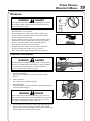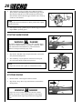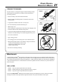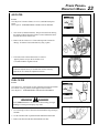
1
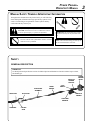
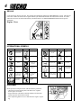
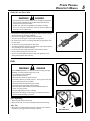
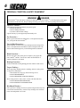
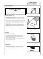
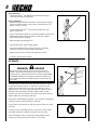
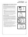
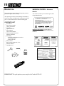
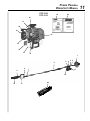
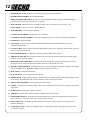
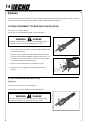
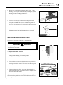
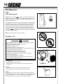
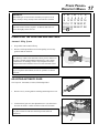
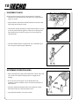
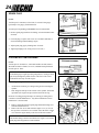
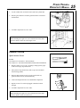
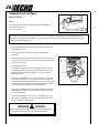
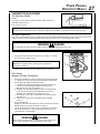
POWER PRUNERTM
OPERATOR'S MANUAL
1
Power PrunerTM
Operator's Manual
MODELS:
PPF-2100 TYPE 1/1E
Serial Number 001001 - 001162
PPF-2110 TYPE 1/1E
Serial Number 001001 - 001016
WARNING
The engine exhaust from this
product contains chemicals known
to the State of California to cause
cancer, birth defects or other
reproductive harm.
WARNING
DANGER
Read rules for safe operation and instructions carefully. ECHO provides an Operator's Manual and a
Safety Manual. Both must be read and understood for proper and safe operation. Failure to do so could
result in serous injury.
X7502302302
89861022662
06/99
2
INTRODUCTION
Welcome to the ECHO family. This ECHO product was designed and manufactured to provide long life and on-the-jobdependability. Read and understand this manual and the SAFETY MANUAL you found in the same package. You will
find both easy to use and full of helpful operating tips and SAFETY messages.
WARNING
DANGER
Read rules for safe operation and instructions carefully. ECHO provides an Operator's Manual and a Safety Manual.
Both must be read and understood for proper and safe operation.
THE OPERATOR'S MANUAL
--
contains specifications and information for operation, starting,
stopping, maintenance, storage and assembly specific to this product.
THE SAFETY MANUAL –
explains possible hazards involved with the use of Power PrunerTM and
what measures you should take to make their use safer.
TABLE OF CONTENTS
Introduction ............................................................... 2
- The Operator's Manual ........................................ 2
- The Safety Manual ............................................. 2
Manual Safety Symbols & Important Information ..... 3
Safety ......................................................................... 3
- General Description ............................................ 3
- Decals ................................................................. 4
- International Symbols ......................................... 4
- Equipment ........................................................... 4
- Fuel ..................................................................... 5
- Personal Condition & Safety Equipment ............ 6
- Safe Operation .................................................... 7
- Kickback ............................................................. 8
- Extended Operation/Extreme Conditions ............ 9
Description .............................................................. 10
- Contents ........................................................... 10
- Emission Control ............................................... 10
Specifications ........................................................... 13
Assembly ................................................................. 14
- Cutting Attachment to Drive Shaft Installation 14
- 3' Extension Installation .................................... 14
- Saw Chain Tension Adjustment ....................... 15
Pre-Operation ........................................................... 16
- Fuel ................................................................... 16
- Lubricating the Guide Bar and Saw Chain ........ 17
- Adjusting Automatic Oiler ................................ 17
- Equipment Check .............................................. 18
- Determine Operation Area ................................ 18
Operation ................................................................. 19
- Starting Cold Engine ......................................... 19
- Starting Warm Engine ....................................... 20
- Stopping Engine ............................................... 20
- Pruning Techniques ......................................... 21
Maintenance ............................................................ 21
- Skill Levels ........................................................ 21
- Maintenance Intervals ...................................... 22
- Air Filter ............................................................ 23
- Fuel Filter .......................................................... 23
- Spark Plug ......................................................... 24
- Cooling System Cleaning .................................. 24
- Exhaust System ................................................. 25
- Carburetor Adjustment Emissions ................... 26
- Carburetor Adjustment Non Emissions ............ 27
- Guide Bar and Saw Chain Replacement ............ 28
- Filing Saw Chain ............................................... 29
Troubleshooting ...................................................... 30
Storage ..................................................................... 31
Servicing Information ............................................... 32
- Parts .................................................................. 32
- Service .............................................................. 32
- ECHO Consumer Product Support .................... 32
- Warranty Card .................................................. 32
- Additional or Replacement Manuals ................ 32
- Manual Ordering Instructions .......................... 32
Specifications, descriptions and illustrative material in
this literature are as accurate as known at the time of
publication, but are subject to change without notice.
Illustrations may include optional equipment and
accessories, and may not include all standard
equipment.
POWER PRUNERTM
OPERATOR'S MANUAL
3
MANUAL SAFETY SYMBOLS & IMPORTANT INFORMATION
Throughout this manual and on the product itself, you will find safety
alerts and helpful, information messages preceded by symbols or key
words. The following is an explanation of those symbols and key
words and what they mean to you.
This symbol accompanied by the words WARNING and
DANGER calls attention to an act or condition that can lead
to serious personal injury to operator and bystanders.
The circle with the slash symbol means whatever is shown
within the circle is prohibited.
IMPORTANT The enclosed message provides
information necessary for the protection of the
unit.
NOTE This enclosed message provides tips for
use, care and maintenance of the unit.
SAFETY
GENERAL DESCRIPTION
IMPORTANT
See Description and Specification sections for full description and illustration of model variation in power head,
and handle type.
THROTTLE
TRIGGER
LOCKOUT
SHAFT TUBE
ASSEMBLY
SAW CHAIN
FRONT
HANDLE
STOP
SWITCH
AUTO OILER
THROTTLE
TRIGGER
SHOULDER
HARNESS
GUIDE BAR
CUTTING
SHOE
POWER
HEAD W/
DECAL
4
DECALS
Locate this safety decal on your unit. The complete unit illustration found in the "DESCRIPTION" section, will help you
locate them. Make sure the decals are legible and that you understand and follow the instructions on them. If a decal
cannot be read, a new one can be ordered from your ECHO dealer. See PARTS ORDERING instructions for specific
information.
Engine Cover
INTERNATIONAL SYMBOLS
Symbol form/shape
Symbol
description/application
Symbol form/shape
Symbol
description/application
Symbol form/shape
Symbol
description/application
DO NOT allow
flames or sparks
near fuel.
Read and understand
Operator's Manual.
Fuel and oil mixture
Wear eyes, ears and
head protection
Finger Severing
Engine choke
control.
Wear hand
protection. Use
two handed.
Emergency stop
Hot
Surface
Safety/Alert
Avoid all power
lines. This unit is not
insulated against
electrical current.
Keep bystanders at
least 15 meters
(50 feet) away.
DO NOT smoke
near fuel.
Do not operate closer than 15 M (50 ft.)
from electrical
hazards.
Plan retreat path
from falling
objects.
EQUIPMENT
Before operation a complete check of the unit must be performed;
• Check unit for loose/missing nuts, bolts and screws. Tighten
and/or replace as needed.
• Inspect fuel lines, tank and area around carburetor for fuel leaks.
DO NOT operate unit if leaks are found.
• Never adjust the guide bar or saw chain when the engine is operating.
Chain lubrication
Carburetor adjustment
- Low speed mixture
Symbol form/shape
Symbol
description/application
Wear slip resistant
foot wear.
Ignition
ON/OFF
Primer bulb
Carburetor adjustment
- High speed mixture
Carburetor adjustment
- Idle speed
POWER PRUNERTM
OPERATOR'S MANUAL
Guide Bar and Saw Chain
WARNING
DANGER
• Serious injury may result from the use of non approved guide bar
and saw chain combinations. Read and comply with all safety
instructions listed in this manual.
• ECHO, INC. will not be responsible for the failure of cutting
devices or accessories which have not been tested and approved
by ECHO for use with this unit.
• Check that the cutting attachment, guide bar and saw chain is firmly
attached and in safe operating condition.
• Only use ECHO approved guide bar and saw chain.
• Only use one ECHO approved extension on the pruner.
• Do not hit rocks, stones, tree stumps and other foreign objects with
the saw chain.
• Do not cut into the ground with the saw chain.
• If cutting attachment end strikes an obstruction, stop engine immediately and inspect saw chain for damage.
• Do not operate with a dull, fractured or discolored saw chain.
• Remove all foreign objects from work area.
• Always cover the guide bar and saw chain with guide bar cover
during transportation and in storage.
FUEL
WARNING
DANGER
Fuel is VERY flammable. Use extreme care when mixing, storing or
handling, or serious personal injury may result.
• Use an approved fuel container.
• DO NOT smoke near fuel.
• DO NOT allow flames or sparks near fuel.
• Fuel tanks/cans may be under pressure. Always loosen fuel caps
slowly allowing pressure to equalize.
• NEVER refuel a unit when the engine is HOT!
• NEVER refuel a unit with the engine running.
• DO NOT fill fuel tanks indoors. ALWAYS fill fuel tanks out
doors over bare ground.
• Securely tighten fuel cap after refueling.
• Inspect for fuel leakage. If fuel leakage is found, do not start or
operate unit until leakage is repaired.
After Refueling;
• Wipe any spilled fuel from the unit.
• Move at least 3 M (10 ft.) from refueling location before starting.
After Use;
• DO NOT store a unit with fuel in its tank. Leaks can occur. Return
unused fuel to an approved fuel storage container.
3M
(10ft.) Minimum
5
6
PERSONAL CONDITION & SAFETY EQUIPMENT
WARNING
DANGER
Power PrunerTM users risk injury to themselves and others if the Power PrunerTM is used improperly and or safety
precautions are not followed. Proper clothing and safety gear must be worn when operating a Power PrunerTM.
Physical Condition -Your judgment and physical dexterity may not be good:
• if you are tired or sick,
• if you are taking medication,
• if you have taken alcohol or drugs.
Operate unit only if you are physically and mentally well.
Eye Protection -Wear eye protection that meets ANSI Z87.1 or CE requirements whenever you operate the Power PrunerTM.
Face & Head Protection -When trimming overhead, always wear head protection meeting ANSI
Z89.1 or CE requirements with a full face shield. Head protection with
full face shield will help protect you from falling branches and debris.
Hand Protection -Wear no-slip, heavy duty work gloves to improve your grip on the
Power PrunerTM handles. Gloves also reduce the transmission of
machine vibration to your hands.
Hearing Protection -ECHO recommends wearing hearing protection whenever unit is used.
Proper Clothing -Wear snug fitting, durable protective clothing; chain saw safety pants
or chaps are recommended.
• Pants should have long legs, shirts with long sleeves.
• DO NOT WEAR SHORTS,
• DO NOT WEAR TIES, SCARVES, JEWELRY.
Wear sturdy protective safety shoes or boots with non-skid soles;
• DO NOT WEAR OPEN TOED SHOES,
• DO NOT OPERATE UNIT BAREFOOTED.
Hot Humid Weather -Heavy protective clothing can increase operator fatigue which may lead
to heat stroke. Schedule heavy work for early morning or late afternoon
hours when temperatures are cooler.
POWER PRUNERTM
OPERATOR'S MANUAL
SAFE OPERATION
WARNING
DANGER
All over head electrical conductors and communications wires can
have electricity flow with high voltages. Never touch wires directly
or indirectly when pruning, otherwise serious injury or death may
result.
Determine Operation Area
• Provide all operators of this equipment with the Operator's Manual,
and instructions for safe operation.
• Do not operate this product indoors or in inadequately ventilated
areas.
• Review the area to be trimmed. Look for hazards that could contribute
to unsafe conditions. DO NOT operate unit if any wires (power,
telephone, cable, etc.) are closer than 15 M (50 ft.) to any part of the
operator or unit.
• Spectators and fellow workers must be warned, and children and
animals prevented from coming nearer than 15 M (50 ft.) while the
Power PrunerTM is in use.
• Avoid all power lines. This unit is not insulated against electrical
current.
Operation
Use Proper Clothing & Equipment
• Before starting the unit, equip yourself and any other person
working within the 15 M (50 ft.) Safety Zone with the required
Protective Equipment and clothing.
• Always wear head protection with full face shield to help protect
against falling branches and debris.
Avoid Hot Surfaces
• During operation, the complete unit, especially the power head,
muffler area and cutting attachment may become very hot, too hot to
touch. Avoid contact during and immediately after operation.
15 M
(50 ft.)
7
8
Keep A Firm Grip
• Grip Power PrunerTM with both hands with thumbs and fingers
encircling the handle, and shaft tube.
Keep A Solid Stance
• Maintain footing and balance at all times. Do not stand on slippery,
uneven or unstable surfaces. Do not work in odd positions or on
ladders. Do not overreach.
• Operate the Power PrunerTM only from the ground or out of an
approved bucket lift.
• Always evaluate the branches to be pruned for hazards such as loose
dead branches which may fall and strike the operator or helpers.
Remove hazards before pruning.
• Plan retreat path from falling objects.
• Cut branches bounce when striking ground.
• Check that shoulder harness is adjusted for safe, comfortable
operation. See picture at right for proper adjustment.
• Turn the Power PrunerTM off when moving from tree to tree.
• Avoid any contact with saw chain.
KICKBACK
WARNING
DANGER
Kickback can lead to dangerous loss of control of the Power
PrunerTM and result in serious injury to the operator or any one
standing close by. Hold the Power PrunerTM firmly with both hands
with thumbs and fingers encircling the front and rear handles. Be
aware of the down and outward path the pruner will take after the
cut is made.
Kickback may occur when the moving saw chain at the nose or tip of
the guide bar touches an object, or when the wood closes in and
pinches the saw chain in the cut. In some cases this may cause a
lightning-fast reverse action, kicking the guide bar and saw chain up
and back or down and back towards the operator. Either of these
reactions may cause the operator to lose control of the Power PrunerTM
which could result in serious personal injury.
With a basic understanding of kickback, you can reduce or eliminate the
element of surprise which contributes to accidents.
Avoid contact of the guide bar tip with any object while the saw chain
is moving.
Cut only wood. Avoid striking concrete, metal, wire, or other obstructions which could cause kickback or damage to the saw chain.
If the saw chain does strike a foreign object, immediately stop the
engine, inspect and repair the Power PrunerTM if necessary.
POWER PRUNERTM
OPERATOR'S MANUAL
EXTENDED OPERATION/EXTREME CONDITIONS
Vibration and Cold
It is believed that a condition called Raynaud’s Phenomenon, which
affects the fingers of certain individuals may be brought about by
exposure to vibration and cold. Exposure to vibration and cold may
cause tingling and burning sensations followed by loss of color and
numbness in the fingers. The following precautions are strongly
recommended because the minimum exposure which might trigger the
ailment is unknown.
• Keep your body warm, especially the head, neck, feet, ankles, hands
and wrists.
• Maintain good blood circulation by performing vigorous arm
exercises during frequent work breaks and also by not smoking.
• Limit the hours of operation. Try to fill each day with jobs where
operating the trimmer or other hand-held power equipment is not
required.
• If you experience discomfort, redness and swelling of the fingers
followed by whitening and loss of feeling, consult your physician
before further exposing yourself to cold and vibration.
Repetitive Stress Injuries
It is believed that overusing the muscles and tendons of the fingers,
hands, arms and shoulders may cause soreness, swelling, numbness,
weakness and extreme pain in those areas. Certain repetitive hand
activities may put you at a high risk for developing a Repetitive Stress
Injury (RSI). An extreme RSI condition is Carpal Tunnel Syndrome
(CTS), which could occur when your wrist swells and squeezes a vital
nerve that runs through the area. Some believe that prolonged exposure
to vibration may contribute to CTS. CTS can cause severe pain for
months or even years.
To reduce the risk of RSI/CTS, do the following:
• Avoid using your wrist in a bent, extended or twisted position.
Instead try to maintain a straight wrist position. Also, when grasping,
use your whole hand, not just the thumb and index finger.
• Take periodic breaks to minimize repetition and rest your hands.
• Reduce the speed and force with which you do the repetitive
movement.
• Do exercises to strengthen the hand and arm muscles.
• Immediately stop using all power equipment and consult a doctor if
you feel tingling, numbness or pain in the fingers, hands, wrists or
arms. The sooner RSI/CTS is diagnosed, the more likely permanent
nerve and muscle damage can be prevented.
9
10
DESCRIPTION
EMISSION CONTROL - Emissions
Models
Due to packaging restriction the ECHO product you have
purchased requires some assembly.
After opening the carton, check for damage. Immediately
notify your retailer or ECHO Dealer of damaged or missing
parts. Use the contents list to check for missing parts.
CONTENTS LIST
__ Power Head
__ Shaft Tube Assembly
__ Cutting Attachment
__ Plastic Bag
__ Operator's Manual
__ Safety Manual
__ How to Prune Manual
__ Warranty Registration Card
__ Warranty Statement
__ Plastic Bag
__ -T-Wrench (Combination screwdriver/
spark plug socket)
__ -3 mm Hex Wrench
__ Safety Glasses
__ Bottle 2-Stroke Engine Oil, 2.6 oz.
__ Shoulder Harness
__ Guide Bar Cover
The emission control system for this engine is EM
(Engine Modification).
IMPORTANT ENGINE INFORMATION
ENGINE FAMILY : TEH021UB24RA
DISPLACEMENT : 21.2cc
THIS ENGINE MEETS U.S. EPA PHI AND 1995 1999 CALIFORNIA EMISSION REGULATIONS FOR
ULGE ENGINES. REFER TO OWNER’S MANUAL
FOR MAINTENANCE SPECIFICATIONS AND
ADJUSTMENTS.
Emission Control Label (located on Engine)
(EXAMPLE ONLY, information on label varies by
FAMILY).
IMPORTANT This spark ignition system complies with Canadian ICES-002
POWER PRUNERTM
OPERATOR'S MANUAL
22
PPF-2100
PPF-2110
23
24
21
20
19
14
18
17
16
15
1
6
8
3 2
5 4
7
13
9
12
10
11
25
11
12
1. POWER HEAD - Includes the Engine, Clutch, Fuel System, Ignition System and Starter.
2. REAR HANDLE ASSEMBLY - Rear (right hand) handle.
3. THROTTLE TRIGGER LOCKOUT - This lever must be held during starting. Operation of the throttle trigger is
prevented unless throttle trigger lockout lever is engaged.
4. STOP SWITCH - Mounted on top of rear handle assembly. Move switch forward to run, back to stop.
5. STRAP HOOK - Used to secure unit to shoulder harness.
6. FRONT HANDLE - Cushioned grip for left hand.
7. CUTTING ATTACHMENT - Sealed, gear ratio is 1.5:1 reduction.
8. AUTOMATIC OILER ASSEMBLY - Self oiling. Use high quality, low viscosity, non detergent bar and chain oil.
9. GUIDE BAR - 254 mm (10 inch) Bar
10. SAW CHAIN - 91 VS 9.53mm (3/8 inch) low profile Oregon® saw chain. Runs approximately 609.6 m/min.
(2000 ft/min) at full throttle.
11. CUTTING SHOE - Used to capture and stabilize branch while cutting. Place cutting shoe against branch, accelerate
and lower saw chain into branch.
12. SHOULDER HARNESS - An adjustable strap that suspends the unit from the operator.
13. THROTTLE TRIGGER - Spring loaded to return to idle when released. During acceleration press throttle trigger
gradually for best operating technique.
14. MUFFLER, SPARK ARRESTER - The muffler controls the exhaust noise while the spark arrestor prevents hot,
glowing particles of carbon from leaving the muffler where they could possibly start a fire.
15. RECOIL STARTER HANDLE - Pull handle slowly until recoil starter engages, then quickly and firmly. When engine
starts return handle slowly. DO NOT let handle snap back or damage will occur.
16. FUEL TANK - Contains fuel and fuel filter.
17. FUEL TANK CAP - Covers and seals fuel tank opening.
18. PRIMER BULB - Pumping primer bulb before starting engine draws fresh fuel from the fuel tank priming the carburetor for starting. Pump the primer bulb 10 times until fuel is visible in clear fuel return line.
19. AIR CLEANER ASSEMBLY - Contains replaceable air filter element.
20. CHOKE - Located above air cleaner housing. Move lever to starting position (close choke) and back to run position
(open choke).
21. SPARK PLUG - Provides spark to ignite fuel mixture.
22. ARM REST - Provides arm rest during operation and protects arm from hot engine.
23. OPERATOR'S MANUAL - Read and understand this manual before operation. Keep manual in a safe location for
future reference, i.e., operation, maintenance, storage and specifications.
24. SAFETY MANUAL - Read before operation and keep in a safe place for future reference to learn proper, safe
operating techniques.
25. GUIDE BAR COVER - Used to cover guide bar and saw chain during transport and storage. Remove guide bar
cover before using unit.
POWER PRUNERTM
OPERATOR'S MANUAL
13
SPECIFICATIONS
MOD EL
PPF-2100
PPF-2110
2.39 m (7 ft, 10 i n.)
Length
3.30 m (10 ft, 10 i n.)
Length w/Opti onal 3 ft. extensi on
Wi dth
0.22 m (8.75 i n.)
Hei ght
0.23 m (9.0 i n.)
Wei ght (dry)
Engi ne Type
5.91 kg (13.0 lb.)
6.9 kg (15.2 lb.)
Ai r cooled, two-stroke, si ngle cyli nder gasoli ne engi ne
32.2 mm (1.268 i n.)
Bore
26.0 mm (1.04 i n.)
Stroke
21.2 cc (1.29 cu. i n.)
D i splacement
Exhaust System
C arburetor
Igni ti on System
Spark Plug
Fuel
Fuel/Oi l Rati o
Gasoli ne
Oi l
Spark Arrestor Muffler
D i aphragm, w/pri mer bulb
C D I (capaci tor di scharge i gni ti on)
NGK BPMR-7A Gap 0.65 mm (0.026 i n.)
Mi xed (Gasoli ne and Two-stroke Oi l)
50:1 EC HO Hi gh Performance, two-stroke ai r cooled engi ne oi l
89 Octane unleaded. D O NOT use fuel contai ni ng methyl alcohol,
more than 10% ethyl alcohol or 15% MTBE.
50:1 EC HO Hi gh Performance, two-stroke ai r cooled engi ne oi l
0.4 li t. (14.0 US fl. oz.)
Fuel Tank C apaci ty
Recoi l Starter System
Automati c Recoi l Starter
C lutch
Sprocket Type
Shaft Tube Assembly
Power Transmi ssi on Shaft
Gear C ase Rati o
Oi li ng System
C hai n Oi l C apaci ty
Handles
C entri fugal Type
6 tooth spur, 9.53 mm (3/8 i nch) pi tch
25.4mm (1") Galvani zed Steel
25.4mm (1i n.) Galvani zed Steel w/vi nyl cover
6.35 mm (1/4 i nch) Flex C able
1.5:1
Automati c
225 ml (7.6 oz.)
Ri ght hand gri p w/throttle tri gger and throttle tri gger lockout / Left foam hand gri p
Shoulder Harness
Standard
Idle Speed (RPM)
2300 - 3000
Wi de Open Throttle Speed (RPM)
Gui de Bar and Saw C hai n
8000 - 11000
254 mm (10 i n.) ; 9.53 mm (3/8 i nch) pi tch chai n
Specifications, descriptions and illustrative material in this literature are as accurate as known at the time of publication,
but are subject to change without notice. Illustrations may include optional equipment and accessories, and may not
include all standard equipment.
14
ASSEMBLY
For your convenience the Power PrunerTM has been shipped with the power head attached and throttle linkage assembled.
We recommend the power head remain attached to the drive shaft and housing at all times.
CUTTING ATTACHMENT TO DRIVE SHAFT INSTALLATION
Tools Required: 3 mm Hex Wrench
Parts Required: Power Head/Drive Shaft; Cutting Attachment
WARNING
DANGER
Saw chain is sharp! Always wear gloves when handling cutting
attachment, otherwise serious personal injury may result.
1. Loosen the (4) four lower bolts (A) on the cutting attachment, and
remove location bolt (B).
2. Slide the cutting attachment onto the shaft housing until the hole
in the neck of the cutting attachment is aligned with the hole (C) in
the housing. (It may be necessary to rotate the saw chain slightly
to align the internal pinion and drive shaft.)
B
C
3. Insert location bolt (B) into hole (C) and tighten to snug.
4. Tighten bolts (A), clamping the cutting attachment onto the
housing.
A
3 FOOT EXTENSION INSTALLATION
(Optional)
Tools Required: Screwdriver, 3 mm Hex Wrench
Parts Required: 914 mm (3 Foot) Extension P/N 99946400010
WARNING
DANGER
Saw Chain is sharp! Always wear gloves when handling cutting
attachment, otherwise serious personal injury may result.
A
POWER PRUNERTM
OPERATOR'S MANUAL
1.
2.
Remove the cutting attachment from the Power PrunerTM shaft
housing by removing the location bolt (B), loosening the (4) four
lower bolts (A) clamping the cutting attachment to the shaft
housing and slide the cutting attachment off.
B
Loosen the 4 screws (D) on the extension clamp and slide the
extension onto the shaft housing until the hole (E) in the extension
clamp lines up with the hole (C) in the shaft housing. Insert the
#8 x 1/2 in. self-tapping screw (F) into hole (C) and tighten to snug.
F
D
E
3.
A
A
Follow the steps outlined in Cutting Attachment to Drive Shaft
Installation to install the cutting attachment to the extension.
D
C
SAW CHAIN TENSION ADJUSTMENT
Tools Required: 10x19mm (13/32x3/4in.) T-wrench provided
WARNING
DANGER
Always wear gloves when handling saw chain, otherwise serious
personal injury may result.
A
To Adjust Saw Chain Tension.
1.
Loosen two (2) 10 mm (13/32 in.) guide bar nuts (A) located on
cutting attachment using the T-wrench provided.
B
2.
Turn saw chain tensioner screw (B) (located next to guide bar in
sprocket cover) clockwise to tighten saw chain on guide bar.
Turning screw counter clockwise will loosen saw chain on guide
bar.
3.
Tighten guide bar nuts firmly. Move saw chain backwards on
guide bar by hand. Saw chain should move freely on guide bar if it
is in proper mesh with sprocket.
Keep the saw chain lubricated and properly adjusted and the guide bar
nuts tightened firmly at all times. If saw chain is difficult to rotate or
binds on guide bar, it is too tight.
15
16
PRE-OPERATION
FUEL
Fuel Requirements
Gasoline - Use 89 Octane [R +2 M ] gasoline or gasohol known to be good
quality. Gasohol may contain up to 10% Ethyl (grain) alcohol or 15%
MTBE (methyl tertiary-butyl ether). Gasohol containing methanol (wood
alcohol) is NOT approved.
Two-Stroke Oil - A two-stroke engine oil meeting ISO-L-EGD Standard
(ISO/CD 13738), must be used. Echo brand Premium 50:1 oil meets this
standard. Engine problems due to inadequate lubrication caused by
failure to use an ISO-L-EGD approved oil, such as Echo Premium 50:1
Two-stroke Oil, will void the two-stroke engine warranty. (Emission
related parts only are covered for two years, regardless of two-stroke
oil used, per the statement listed in the EPA Phase I/California Emission
Defect Warranty Explanation.)
Mixing - Follow directions on the oil container.
Handling Fuel
WARNING
DANGER
Fuel is VERY flammable. Use extreme care when mixing, storing or
handling, or serious personal injury may result.
• Use an approved fuel container.
• DO NOT smoke near fuel.
• DO NOT allow flames or sparks near fuel.
• Fuel tanks/cans may be under pressure. Always loosen fuel caps
slowly allowing pressure to equalize.
• NEVER refuel a unit when the engine is HOT!
• NEVER refuel a unit with the engine running.
• DO NOT fill fuel tanks indoors. ALWAYS fill fuel tanks out
doors over bare ground.
• Securely tighten fuel cap after refueling.
• Inspect for fuel leakage. If fuel leakage is found, do not start or
operate unit until leakage is repaired.
After Refueling;
• Wipe any spilled fuel from the unit.
• Move at least 3 M (10 ft.) from refueling location before starting
the engine.
After use;
• DO NOT store a unit with fuel in its tank. Leaks can occur.
Return unused fuel to an approved fuel storage container.
Storage Fuel storage laws vary by locality. Contact your local government for
the laws affecting your area. As a precaution, store fuel in an approved,
air tight container. Store in a well ventilated, unoccupied building, away
from sparks and flames. Do not store fuel longer than 30 days.
3M
(10ft.) Minimum
POWER PRUNERTM
OPERATOR'S MANUAL
IMPORTANT
Stored fuel ages. Do not mix more fuel than you expect to use in
thirty (30) days, ninety (90) days when a fuel stabilizer is added.
IMPORTANT
Stored two-stroke fuel may separate. ALWAYS shake fuel container thoroughly before each use.
S M
1 2
8 9
15 16
22 23
29 30
T
3
10
17
24
31
LUBRICATING THE GUIDE BAR AND SAW CHAIN
Automatic Oiling System
1.
Wipe debris from around oil fill cap.
2.
Remove oil fill cap and fill reservoir with a quality, low viscosity
guide bar and saw chain oil.
NOTE
The discharge volume of the automatic oiler is preset to deliver 3 to
4 cc/min. at normal operating RPM. During heavy or dry cutting
conditions the oil discharge volume may be adjusted to assure
adequate lubrication. Refill the oil reservois with each tank of fuel.
IMPORTANT
To prevent plastic deterioration, do not use synthetic or silicone
based oil.
ADJUSTING AUTOMATIC OILER
Tools required: 10x19mm (13/32x3/4) T-Wrench provided
1.
Remove two (2) 10 mm guide bar retaining nuts and sprocket cover.
2.
From bottom of gear case, turn adjustment screw (A) clockwise to
decrease oil volume - counter clockwise to increase oil volume.
NOTE
Very little visible oil on the saw chain will provide sufficient
lubrication.
A
W T F S
4 5 6 7
11 12 13 14
18 19 20 21
25 26 27 28
17
18
EQUIPMENT CHECK
Before operation a complete check of the unit must be performed;
• Check unit for loose/missing nuts, bolts and screws. Tighten and/or
replace as needed.
• Inspect fuel lines, tank and area around carburetor for fuel leaks. DO
NOT operate unit if leaks are found.
• Check that the cutting attachment is firmly attached and the saw chain
is correctly tensioned on the guide bar. Dull, loose or damaged saw
chain should not be used. Refer to page 29 for correct Filing Saw
Chain procedure.
• Check that shoulder harness is adjusted for safe, comfortable operation. See figure at right for proper adjustment.
DETERMINE OPERATION AREA
• Before starting the unit, equip yourself and fellow workers in the 15 M
(50 ft.) safety zone with the required protective equipment and
clothing.
• Review the area to be trimmed. Look for hazards that could
contribute to unsafe conditions, such as overhead electrical lines or
dead branches.
• Spectators, children and animals must be prevented from coming
nearer than 15 M (50 ft.) while the pruner is in use.
• Large branches should be removed in sections.
15 M
(50 ft.)
POWER PRUNERTM
OPERATOR'S MANUAL
OPERATION
WARNING
DANGER
Do not operate this product indoors or in inadequately ventilated
areas. Engine exhaust contains poisonous emissions which can
cause serious injury or death.
• Provide all operators of this equipment with the Operator's Manual,
and instructions for safe operation.
• Before starting the unit, equip yourself and any other person
working within the 15 M (50 ft.) Safety Zone with the required
Protective Equipment and clothing.
• Always evaluate the area being cut for overhead hazards, such as
dead branches which may fall and strike the operator or helpers.
• Be aware of branches bouncing when striking the ground.
• Larger branches should be removed in sections.
• During operation, the complete unit, especially the shaft tube
and bearing housing may become very hot, too hot to
touch. Avoid contact during and immediately after operation.
STARTING COLD ENGINE
A
WARNING
DANGER
The cutting attachment should not move at idle. If cutting attachment moves, readjust carburetor according to "Carburetor Adjustment" instructions in this manual or see your ECHO Dealer,
otherwise serious personal injury may result.
1.
Stop Switch - Start/Run.
Move stop switch button (A) forward away from the STOP
position.
2.
Choke - Cold Start.
Move choke (B) to “Cold Start” Position.
3.
Primer Bulb -Purge.
Pump primer bulb (C) 10 times. Fuel will be visible and flow freely in
the clear fuel tank return line.
WARNING
DANGER
Inspect starting area for hazards such as rocks, glass, debris etc.
which could be contacted by the cutting attachment when starting.
Keep helpers and bystanders at least 15 M (50 ft.) from starting
area, otherwise serious personal injury may result.
4.
B
Lay the pruner on a flat clear area. Firmly grasp right hand grip and
throttle trigger lockout with left hand and fully depress throttle
trigger to wide open position. Rapidly pull recoil starter handle/rope
(D) until engine fires (or maximum five [5] pulls).
C
D
19
20
5.
After engine fires (or five [5] pulls), move choke lever back to
“Run” position. Hold throttle trigger and throttle trigger lockout
fully depressed and pull recoil starter handle/rope until engine
starts and runs. Release throttle trigger and allow unit to warm up
at idle for several minutes.
NOTE
If engine does not start with choke in “Run” position after 5 pulls,
repeat instructions.
6.
After engine warm up, gradually depress throttle trigger to increase
engine RPM to operating speed.
STARTING WARM ENGINE
A
WARNING
DANGER
The cutting attachment should not move at idle. If cutting attachment moves, readjust carburetor according to "Carburetor Adjustment" instructions in this manual or see your ECHO Dealer,
otherwise serious personal injury may result.
1.
Stop Switch - Start/Run. Move Stop Switch button (A) forward
away from the STOP position.
2.
Start - Pull Rope. Lay the pruner on a flat clear area and pull
the recoil starter handle (D) until the engine fires.
NOTE
If engine does not start after 5 pulls, use Cold Start Procedure.
D
STOPPING ENGINE
1.
Release Throttle. Allow engine to idle for a minute.
2.
Stop Switch - Stop. Move stop switch button (A) backward to
STOP position.
WARNING
DANGER
If engine does not stop when stop switch is moved to STOP
position, close choke - COLD START position - to stall engine.
Have your ECHO dealer repair stop switch before using pruner
again.
A
POWER PRUNERTM
OPERATOR'S MANUAL
21
PRUNING TECHNIQUES
The Power PrunerTM is designed for light to medium trimming of limbs
and branches up to 203mm (8 in.) in diameter. Follow these tips for
successful operation.
CORRECT
• Plan cut carefully. Check direction branch will fall.
• Plan retreat path from falling branch. Cut branches bounce when
striking ground.
• Long branches should be removed in several pieces.
GUIDE AGAINST
BRANCH
NOT
CORRECT
• Do not stand directly beneath branch being cut.
• When ready to cut:
Hold "cutting shoe" against branch. This will prevent whipping of the
branch. DO NOT use back and forth sawing action.
• Look out for branch immediately behind the branch being cut. If saw
chain hits rear branch damage to saw chain and guide bar may occur.
• Accelerate to full throttle.
BLADE HITS REAR BRANCH
• Apply cutting pressure.
• Ease cutting pressure when nearing end of cut to maintain control.
• When pruning a limb 102 mm (4 in.) diameter or larger cut as follows:
1. Under cut 1/4 limb diameter near tree trunk.
2. Finish top cut slightly farther out on limb.
3. Flush cut stub at trunk.
• DO NOT use for felling or bucking.
NOT
CORRECT
MAINTENANCE
Your ECHO Power PrunerTM is designed to provide many hours of trouble free service. Regular scheduled maintenance
will help your pruner achieve that goal. If you are unsure or are not equipped with the necessary tools, you may want to
take your unit to an ECHO Service Dealer for maintenance. To help you decide whether you want to DO-IT-YOURSELF
or have the ECHO Dealer do it, each maintenance task has been graded. If the task is not listed, see your ECHO Service
Dealer for repairs.
SKILL LEVEL
Level 1 = Easy to do. Most required tools come with unit.
Level 2 = Moderate difficulty. Some specialized tools may be required.
Level 3 = Experience required. Specialized tools are required.
ECHO offers REPOWERTM Maintenance Kits and Parts to make your maintenance job easier. Just below each task
heading are listed the various part numbers required for that task. See your ECHO dealer for these parts.
22
MAINTENANCE INTERVALS
COMPONENT/
SYSTEM
MAINTENANCE
PROCEDURE
REQ'D
SKILL
LE V E L
DAILY OR
BEFORE
U SE
EVERY
R E FU E L
3
MONTHS
OR 90
HOURS
6
MONTHS
OR 270
HOURS
YEARLY
600
HOURS
Recommended Echo Dealer Maintenance Procedures
Cylinder Exhaust Port
Inspect/Clean/Decarbon
3
I/C
Do-It-Yourself Maintenance Procedures
Air Filter
Inspect/Clean/Replace
1
I/C
Choke System
Inspect/Clean
2
I/C
Fuel Filter
Inspect/Replace
1
Fuel System, leaks
Inspect/Replace
1
I/R*
Cooling System
Inspect/Clean
2
I/C
Muffler Spark Arrestor
Inspect/Replace
2
Power Transmission
Shaft
Inspect/Clean/Oil
2
I (1)
Guide Bar
Inspect/Clean/Lubricate
2
I/C
I
Saw Chain
Inspect/Sharpen/Replace/
Lubricate
2
I / R*
I
Recoil Starter Rope
Inspect/Clean
1
I / R*
Spark Plug
Inspect/Clean
2
Screws/Nuts/Bolts
Inspect/Tighten/Replace
1
I*
I
I
I/R*
I
I/R*
I
I/C
R*
I/R*
MAINTENANCE PROCEDURE LETTER CODES: I = INSPECT, R = REPLACE, C = CLEAN
IMPORTANT NOTE - Time intervals shown are maximum. Actual use and your experience will determine the frequency of required
maintenance.
MAINTENANCE PROCEDURE NOTES:
* All recommendations to replace are based on the finding of damage or wear during inspection.
(1) Apply ECHO® LUBETM every 25 hours of use.
POWER PRUNERTM
OPERATOR'S MANUAL
AIR FILTER
Level 1.
Tools Required: 25mm or 50mm (1 in. or 2 in.) medium bristle paint
brush
Parts required: . 90008 REPOWERTM AIR & FUEL FILTER KIT.
1. Close choke (Cold Start Position). This prevents dirt from entering
the carburetor throat when the air filter is removed. Brush accumulated dirt from the air cleaner area.
2. Remove the air cleaner cover. Clean and inspect the element for
damage. If element is fuel soaked and very dirty, replace.
3. If element can be cleaned and reused, be certain it:
-properly fits the cavity in the air cleaner cover.
-is installed with the original side out.
NOTE
Carburetor adjustment may be needed after air filter cleaning/
replacement. See Carburetor Adjustment Section.
FUEL FILTER
Level 1.
Tools Required: 203-254 mm (8-10in.) length of wire with one end bent
into a hook. Clean rag, funnel, and an approved fuel container
Parts Required: 90008 REPOWERTM AIR & FUEL FILTER KIT.
WARNING
DANGER
Fuel is VERY flammable. Use extreme care when mixing, storing or
handling or serious personal injury may result.
1. Use a clean rag to remove loose dirt from around fuel cap and empty
fuel tank.
2. Use the “fuel line hook” to pull the fuel line and filter from the tank.
3. Remove the filter from the line and install the new filter.
23
24
SPARK PLUG
Level 2.
Tools Required: 10x19mm (13/32x3/4in.) T-wrench, Feeler gauge,
(preferably a wire gauge), Soft metal brush
Parts Required: Spark Plug, NGK BPMR-7A; P/N 15901010230
1. Remove spark plug and check for fouling, worn and rounded center
electrode.
2. Clean the plug or replace with a new one. DO NOT sand blast to
clean. Remaining sand will damage engine.
3. Adjust spark plug gap by bending outer electrode.
4. Tighten spark plug to 145-155 kg/cm (125-135 in. lb.).
0.65 mm
(0.026 in.)
COOLING SYSTEM CLEANING
Level 3.
Tools Required: Screwdriver, 3 mm and 4 mm Hex wrench, Pointed
Wood Stick, 25mm or 50mm (1 in. or 2 in.) medium bristle paint brush
Parts Required: None.
IMPORTANT
To maintain proper engine operating temperatures, cooling air must
pass freely through the cylinder fin area. This flow of air carries
combustion heat away from the engine.
Overheating and engine seizure can occur when:
•
•
Air intakes are blocked, preventing cooling air from reaching the
cylinder.
Dust and grass build up on the outside of the cylinder. This build
up insulates the engine and prevents the heat from leaving.
Removal of cooling passage blockages or cleaning of cooling fins is
considered “Normal Maintenance”. Any failure attributed to lack of
maintenance is not warranted.
A
1.
2.
Remove spark plug lead from spark plug and throttle linkage end
from the carburetor swivel.
Remove the four screws that retain the engine cover (A). Two at
the top of the recoil starter, two on either side of the front. Lift the
cover from the engine and lay to the front of the Power PrunerTM.
NOTE
The throttle linkage remains assembled to the engine cover and the
spark plug lead and grommet remain installed.
POWER PRUNERTM
OPERATOR'S MANUAL
3.
Use the wooden stick or brush to remove dirt from cylinder fins.
4.
Remove grass and leaves from the grid between the recoil starter
and fuel tank.
5.
Assemble components in reverse order.
NOTE
When installing the engine cover, be certain the tab of the metal
deflector shield is in the slot of the engine cover.
EXHAUST SYSTEM
Spark Arrestor Screen
Level 2.
Tools Required: Screwdriver, Soft metal brush
Parts Required: Screen P/N 14586240630, Gasket Lid P/N 14586642031
1.
Remove engine cover (A). See “Cleaning Cooling System” pages
24 & 25 for step by step instructions.
2.
Place piston at Top Dead Center (TDC) to prevent carbon/dirt
from entering cylinder.
3.
Remove spark arrestor screen cover (B), screen holder (C),
gasket (D) and screen (E) from muffler body.
4.
Clean carbon deposits from screen and muffler components.
5.
Replace screen if it is cracked, plugged or has holes burned
through.
6.
Assemble components in reverse order.
NOTE
When installing the engine cover, be certain the tab of the metal
deflector shield is in the slot of the cover.
E
D
C
B
25
26
CARBURETOR ADJUSTMENT
Emission Models
Level 2.
Tools Required: Screwdriver with 2mm blade width, Tachometer
(ECHO P/N 99051130017)
Parts required: None.
NOTE
Every unit is run at the factory and the carburetor is set in compliance with EPA Phase 1 and California Emission
Regulations. In addition, the carburetor is equipped with HI (A) and LO (B) needle adjustment limiters that prevent
settings outside acceptable limits.
1.
Before adjusting the carburetor, clean or replace the air filter and
spark arrester screen.
2.
Start engine and run for several minutes to reach operating
temperature.
3.
Stop engine. Turn HI (A) speed needle CCW (counter clockwise)
to stop. Turn LO (B) speed needle midway between full CCW and
CW (clockwise) stops.
4.
Idle Speed Adjustment.
-Start engine and turn idle (C) speed adjustment screw CW until
the cutting attachment begins to turn, then turn the screw CCW
until cutting attachment stops turning. Turn screw CCW an
additional 1/4 turn.
5.
Accelerate to full throttle for 2-3 seconds to clear excess fuel from
engine then return to idle. Accelerate to full throttle to check for
smooth transition from idle to full throttle. If engine hesitates, turn
LO (B) needle CCW an additional 1/8 turn and repeat acceleration.
Continue adjusting until smooth acceleration results.
6.
Check HI speed RPM at W.O.T. (Wide Open Throttle). HI speed
RPM should be set to specifications found on page 13 "Specifications" of this manual.
7.
Check idle speed and reset if necessary. If a tachometer is available, idle speed should be set to the specification found on page
13 "Specifications" of this manual.
WARNING
DANGER
When carburetor adjustment is completed, saw chain should not
move at idle, otherwise serious personal injury may result.
POWER PRUNERTM
OPERATOR'S MANUAL
27
CARBURETOR ADJUSTMENT
Non Emissions Models
Level 2
Tools Required: Screwdriver with 2mm blade width, Tachometer
(ECHO P/N 99051130017)
Parts required: None.
NOTE
If carburetor has limiter caps follow "Carburetor Adjustment" procedures for Emission models on previous page.
Idle Speed Adjustment
Turn "idle" speed adjustment screw (C) CW (clockwise) until cutting attachment begins to turn, then turn screw out CCW
(counter clockwise) until cutting attachment stops turning. Turn screw out, CCW an additional 1/4 turn.
WARNING
DANGER
Saw chain must not turn when unit is idling, otherwise serious personal injury may result.
Basic Setting
1.
Stop engine and turn both LO (B) and HI (A) needles in, CW until
they stop and are lightly seated.
IMPORTANT
DO NOT over tighten needles. Forcing them to tighten will
damage the carburetor.
2.
Turn needles out CCW: LO (B) 3/4 turns; HI (A) 1-3/4 turns.
Fine Tuning
(Requires Accurate Tachometer)
1.
2.
3.
4.
Start engine and allow to warm to operating temperature (minimum
2 - 3 minutes) while varying engine speed from idle to full throttle.
Always begin fine tuning with LO (B) needle.
a. Lean drop-off - With engine idling, turn LO (B) needle slowly
CW (in) to lean drop-off point. RPM will increase, then
abruptly drop-off. Note this position. (1)
b. Rich drop-off - With engine idling, slowly turn LO (B) needle
CCW (out) to rich drop-off point. RPM will increase then
gradually slow and drop-off. Note this position. (2)
c. Final setting - Set needle at mid point between lean rich dropoff points. (3)
d. Turn needle 1/8 turn CCW (out) making mixture slightly
richer. (4)
HI speed adjustment.
Adjust HI (A) needle with tachometer. Refer to Wide Open Throttle
RPM settings listed in "Specifications" on page 13.
Check idle speed and reset if necessary. If tachometer is available,
idle speed should be set to the specifications found on page 13
"Specifications" of this manual.
WARNING
DANGER
When carburetor adjustment is completed, saw chain should not
move at idle, otherwise serious personal injury may result.
28
GUIDE BAR AND SAW CHAIN REPLACEMENT
WARNING
DANGER
Never try to replace or adjust guide bar and saw chain with engine running. This saw chain is VERY sharp, wear
heavy gloves to protect your hands when handling it. Wear eye protection meeting CE or ANSI specification Z87.1.
Guide Bar Replacement / Installation
Level 3
Tools Required: 10x19mm (13/32x3/4 in.) T-Wrench
•
Remove two (2) 10 mm (13/32 in.) guide bar nuts (A) and relieve saw
chain tension turning screw (B) counter clockwise.
•
Remove sprocket cover.
•
Free saw chain from sprocket and remove from guide bar. If guide
bar is okay proceed to saw chain installation.
•
Slide guide bar forward and remove from cutting attachment. Install
new guide bar sliding it onto the cutting attachment as far as
possible.
•
Turn saw chain adjustment screw until adjusting pin (C) fits into
round hole in guide bar.
A
B
Saw Chain Installation
Level 3
•
Install new saw chain onto guide bar. Make sure cutting links are
faced towards the nose of the guide bar.
•
Engage saw chain with sprocket.
•
Secure sprocket cover with (2) two guide bar nuts.
•
Follow instruction for adjusting saw chain tension page 15.
C
POWER PRUNERTM
OPERATOR'S MANUAL
29
FILING SAW CHAIN
Level 3.
Tools Required: 4.5 mm round File P/N 89751001130; Flat File
P/N 89751100230; Depth Gauge P/N 89751400232.
IMPORTANT
Dull or damaged cutters will result in poor cutting performance,
increased vibration and premature saw chain failure.
WARNING
DANGER
Always stop engine and wear gloves when filing saw chain,
otherwise serious personal injury may result.
1. Set round file (A) in cutter at 30° angle. One fifth (1/5) of the file
should be exposed above top cutter edge.
2. Keep file horizontal in cutter and file in one direction.
3. File until cutter top and side bevel edges are sharp without nicks.
4. Place depth gauge tool (B) firmly on top of cutter with .025" slot
and end against front cutter raker. File cutter raker with flat file
until flush with top of depth gauge.
5. Finish cutter sharpening by rounding front raker edge (C) with flat
file.
(SIDE PLATE ANGLE)
(TOP PLATE ANGLE)
6. Properly filed cutter is as shown.
7. Apply clean oil and rotate saw chain slowly to wash away filings.
8. If saw chain is coated or clogged with resin, clean in kerosene then
soak in oil.
(TOP PLATE CUTTING ANGLE)
(DEPTH GAUGE)
30
TROUBLESHOOTING
Problem
Engine
starts hard
does not start
Engine
Cranks
Cause
Remedy
Fuel strainer clogged
Fuel line clogged
Carburetor
Carburetor
Clean
Clean
See your Echo dealer
See your Echo dealer
Muffler wet
with fuel
Fuel mixture is too rich
Spark at
end of
plug wire
No spark at end
of plug wire
Stop switch off
Electrical problem
Interlock switch
Open choke
Clean/replace air filter
Adjust carburetor
See your Echo dealer
Turn switch on
See your Echo dealer
See your Echo dealer
Spark at
plug
No spark at plug
Spark gap incorrect
Covered with carbon
Fouled with fuel
Spark plug defective
Adjust. 0.65 mm (0.026 in.)
Clean or replace
Clean or replace
Replace plug
Internal engine problem
See your Echo dealer
Air filter dirty
Fuel filter dirty
Fuel vent plugged
Spark plug
Carburetor
Cooling system plugged
Exhaust port/spark
arrestor screen plugged
Clean or replace
Replace
Replace
Clean and adjust/replace
Adjust
Clean
Clean
Fuel at
carburetor
Fuel at
cylinder
No fuel at
carburetor
No fuel at
cylinder
Engine
does not
crank
Engine
runs
Dies or
Accelerates poorly
POWER PRUNERTM
OPERATOR'S MANUAL
STORAGE
Long Term Storage (over 30 days)
Do not store your unit for a prolonged period of time (30 days or longer)
without performing protective storage maintenance which includes the
following:
1. Store unit in a dry, dust free place, out of the reach of children.
WARNING
DANGER
Do not store in enclosure where fuel fumes may accumulate or
reach an open flame or spark or serious personal injury may result.
2. Place the stop switch (A) in the "OFF" position.
3. Remove accumulation of grease, oil, dirt and debris from exterior of
unit.
4. Perform all periodic lubrication and services that are required.
5. Tighten all the screws and nuts.
6. Drain the fuel tank completely and pull the recoil starter handle
several times to remove fuel from the carburetor.
7. Remove the spark plug and pour 7 cc (1/4 oz.) [1/2 tablespoon] of
fresh, clean, two-stroke engine oil into the cylinder through the
spark plug hole.
A. Place a clean cloth over the spark plug hole.
B. Pull the recoil starter handle 2-3 times to distribute the oil
inside the engine.
C. Observe the piston location through the spark plug hole. Pull
the recoil starter handle slowly until the piston reaches the top
of its travel and leave it there.
8.
Install the spark plug (do not connect spark plug cable).
9.
Install the guide bar cover on the guide bar and saw chain during
storage.
A
31
SERVICING INFORMATION
PARTS
Genuine ECHO Parts and ECHO REPOWERTM Parts and Assemblies for
your ECHO products are available only from an Authorized ECHO
Dealer. When you do need to buy parts always have the Model
Number, Type number and Serial Number of the unit with you. You can
find all three numbers on the engine housing. For future reference,
write them in the space provided below.
Model No. ____________Type No. ____________ SN. __________
SERVICE
DEALER?
Service of this product during the warranty period must be performed
by an Authorized ECHO Service Dealer. For the name and address of
the Authorized ECHO Service Dealer nearest you, ask your retailer or
call: 1-800-432-ECHO (3246). When presenting your unit for
Warranty service/repairs, proof of purchase is required.
ECHO CONSUMER PRODUCT SUPPORT
If you require assistance or have questions concerning the application,
operation or maintenance of this product you may call the ECHO
Consumer Product Support Department at 1-800-673-1558 from 8:00 am
to 5:00 pm (Central Standard Time) Monday through Friday. Before
calling, please know the model and serial number of your unit to help
your Consumer Product Support Representative.
Call
1-800-432-ECHO
CONSUMER PRODUCT
SUPPORT
1-800-673-1558
8 - 5 Mon - Fri C.S.T.
WARRANTY CARD
This card is our means of registering all original owners of ECHO
equipment. The card plus proof of purchase provides you the assurance that authorized warranty work will be done. It also provides a
direct link between you and ECHO if we find it necessary to contact
you.
ADDITIONAL OR REPLACEMENT MANUALS
Safety Manuals P/N X752000000 are available, free of charge, from your
ECHO dealer or by contacting Echo Incorporated, 400 Oakwood Road,
Lake Zurich, IL 60047.
Operator's and Parts Manuals are available for purchase from your
ECHO dealer or directly from ECHO. [See ordering instructions below.]
ECHO Incorporated
400 Oakwood Road
Lake Zurich, IL 60047
Technical Publications Orders
ORDERING INSTRUCTIONS
To obtain a Parts Catalog or Operator's Manual send a check or money order for $2.00 per Parts Catalog or $1.50 per
Operator's Manual made payable to ECHO, INCORPORATED. State on a sheet of paper the model number and serial
number of the ECHO unit you have, part number of the manual (if known), your name and address and mail to address
above.
Available Parts Catalog
PPF-2100 Type 1/1E S/N 506100 & Up
PPF-2110 Type 1/1E S/N 501890 & Up
99922203001
99922203001
ECHO, INCORPORATED
400 OAKWOOD ROAD
LAKE ZURICH, IL 60047