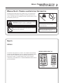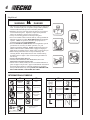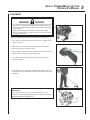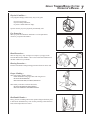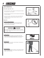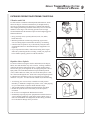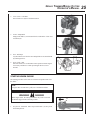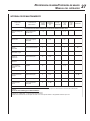
1
Grass Trimmer/Brush Cutter
Operator's Manual
MODELS,
SRM - 2601
SRM - 2610
Serial Number 001001 & Up
WARNING
The engine exhaust from this
product contains chemicals known
to the State of California to cause
cancer, birth defects or other
reproductive harm.
WARNING
DANGER
Read rules for safe operation and instructions carefully. ECHO provides an Operator's
Manual and a Safety Manual. Both must be read and understood for proper and safe
operation. Failure to do so could result in serous injury.
X7502090701
89851957731
02/00
2
INTRODUCTION
Welcome to the ECHO family. This ECHO product was designed and manufactured to provide long life and on-the-jobdependability. Read and understand this manual and the SAFETY MANUAL you found in the same package. You will
find both easy to use and full of helpful operating tips and SAFETY messages.
WARNING
DANGER
Read rules for safe operation and instructions carefully. ECHO provides an Operator's Manual and a Safety Manual.
Both must be read and understood for proper and safe operation.
THE OPERATOR'S MANUAL
—
contains specifications and information for operation, starting,
stopping, maintenance, storage and assembly specific to this product.
THE SAFETY MANUAL
—
explains possible hazards involved with the use of Grass Trimmers and
Brush Cutters and what measures you should take to make their use
safer.
TABLE OF CONTENTS
Introduction ........................................................................ 2
- The Operator's Manual ........................................... 2
- The Safety manual ................................................... 2
Manual Safety Symbols and Important Information ......... 3
Safety ................................................................................. 3
- Decals ...................................................................... 3
- International Symbols .............................................. 4
- Equipment ............................................................... 4
- Fuel .......................................................................... 5
- Personal Condition and Safety Equipment .............. 6
- Safe Operation ......................................................... 7
- Extended Operation/Extreme Conditions ................ 9
Description ....................................................................... 10
- Contents ................................................................ 10
- Blade Terms and Definitions ................................. 10
- Emission Control ................................................... 11
Specifications .................................................................... 13
Assembly .......................................................................... 14
- Drive Shaft/Power Head ........................................ 14
- Throttle Linkage and Ignition Leads ...................... 14
- Plastic Shield Installation ....................................... 15
- Nylon Head Installation ........................................ 15
- Front Handle Installation ....................................... 15
- Accessory Installation ........................................... 16
- Harness Clamp Installation ................................... 16
- Install Metal Shield ................................................ 17
- U-Handle Installation ............................................ 17
- Muffler Bracket Installation .................................. 20
Pre-Operation ................................................................... 20
- Operation with Blades ........................................... 20
- Fuel ........................................................................ 22
CopyRight© 1999 By Echo, Incorporated
All Rights Reserved.
- Equipment Check .................................................. 23
- Determine Operation Area .................................... 24
Operation .......................................................................... 24
- Starting Cold Engine .............................................. 24
- Starting Warm Engine ............................................ 25
- Stopping Engine ..................................................... 26
Maintenance ..................................................................... 26
- Skill Levels ............................................................. 26
- Maintenance Intervals ........................................... 27
- Air Filter ................................................................ 28
- Fuel Filter .............................................................. 28
- Spark Plug .............................................................. 29
- Cooling System Cleaning ....................................... 29
- Exhaust System ..................................................... 30
- Carburetor Adjustment .......................................... 31
- Lubrication ............................................................. 32
- Nylon Line Replacement ....................................... 32
- Sharpening Metal Blades ....................................... 34
Troubleshooting ................................................................ 35
Storage .............................................................................. 36
Servicing Information ........................................................ 40
- Parts ....................................................................... 40
- Service .................................................................... 40
- ECHO Consumer Product Support ................. 40
- Warranty Card ....................................................... 40
- Additional or Replacement Manuals ..................... 40
- Manual Ordering Instructions ............................... 40
Specifications, descriptions and illustrative material in
this literature are as accurate as known at the time of
publication, but are subject to change without notice.
Illustrations may include optional equipment and
accessories, and may not include all standard equipment.
GRASS TRIMMER/BRUSH CUTTER
OPERATOR'S MANUAL
3
MANUAL SAFETY SYMBOLS AND IMPORTANT INFORMATION
Throughout this manual and on the product itself, you will find safety
alerts and helpful, information messages preceded by symbols or key
words. The following is an explanation of those symbols and key words
and what they mean to you.
This symbol accompanied by the words WARNING and
DANGER calls attention to an act or condition that can lead to
serious personal injury to operator and bystanders.
The circle with the slash symbol means whatever is shown
within the circle is prohibited.
IMPORTANT The enclosed message
provides information necessary for the
protection of the unit.
NOTE This enclosed message provides tips for
use, care and maintenance of the unit.
SAFETY
DECALS
DEBRIS SHIELD DECAL
Locate these safety decals on your unit. The complete unit illustration,
found in the "DESCRIPTION" section, will help you locate them. Make
sure the decals are legible and that you understand and follow the
instructions on them. If a decal cannot be read, a new one can be
ordered from your ECHO dealer. See PARTS ORDERING instructions for
specific information.
Plastic Debris
Shield
Metal Debris
Shield
4
Shaft Decal
WARNING
DANGER
• This unit can be dangerous and cause serious injury if improperly
used. To reduce injury risk to operator, helpers and bystanders,
read and understand the Operator's and Safety manuals.
• Blindness can occur from objects that are thrown or ricocheted
evenwith shield in place. Operators, helpers and bystanders
must wear ANSI Z87.1 approved eye protection.
• Always wear hearing protection when operating unit.
• Prevent accidental contact with unit and any cutting attachment.
Maintain a 15M (50 ft.) radius, DANGER ZONE surrounding the
operator. ONLY the operator, dressed in proper protective
clothing should be in the DANGER ZONE.
• Beware of KICKOUT (blade thrust) when using blades. Special
precautions are necessary for blade operation, see your
Operator's and Safety Manuals. ONLY install ECHO approved
blades on Brush Cutters (SRM) models equipped with proper
blade shield, U-handles, harness, blade collar, nut and cotter pin.
• Blade/Cutting attachment does not stop immediately after
releasing throttle. Keep hands and feet clear of blade/cutting
attachment unless engine is shut off and cutting attachment is
not moving.
• INSPECT BLADES BEFORE USE.
• DO NOT USE DAMAGED, CRACKED, BENT, DULL OR
IMPROPERLY SHARPENED BLADES.
• Do not remove shields, modify the unit or install attachments or
parts not approved by ECHO. Approved attachment information
and replacement Operator's and Safety Manuals are available
from your ECHO dealer or by writing: ECHO, INCORPORATED,
400 OAKWOOD RD., LAKE ZURICH, IL 60047.
INTERNATIONAL SYMBOLS
Symbol form/shape
Symbol
description/application
"WARNING, SEE
OPERATOR'S
MANUAL
Wear eyes, ears and
head protection
Wear hand and
foot protection
Safety/Alert
Symbol form/shape
Symbol
description/application
Hot
Surface
Finger Severing
Symbol form/shape
Symbol
description/application
Symbol form/shape
Symbol
description/application
Fuel and oil mixture
Emergency stop
Carburetor adjustment
- High speed mixture
Primer Bulb
DO NOT allow
flames or sparks
near fuel.
Carburetor adjustment
- Idle speed
Ignition
ON/OFF
DO NOT smoke
near fuel.
Carburetor adjustment
- Low speed mixture
Keep bystanders and helpers
away 15 m (50 ft.).
Engine choke
control.
GRASS TRIMMER/BRUSH CUTTER
OPERATOR'S MANUAL
EQUIPMENT
WARNING
DANGER
• Use only ECHO approved attachments. Serious injury may result
from the use of a non approved attachment combination. Read
and comply with all safety instructions listed in this manual and
safety manual.
• ECHO, INC. will not be responsible for the failure of cutting
devices, attachments or accessories which have not been tested
and approved by ECHO.
Before operation a complete check of the unit must be performed;
• Check unit for loose/missing nuts, bolts and screws. Tighten and/or
replace as needed.
• Inspect fuel lines, tank and area around carburetor for fuel leaks.
DO NOT operate unit if leaks are found.
• Inspect shield for damage and ensure that the cut-off knife issecurely
in place. Replace if either is damaged or missing.
• Check that the cutting attachment is firmly attached and in safe
operating condition.
• Check that front (loop) handle and optional shoulder/waist harness
are adjusted for safe, comfortable operation. See Assembly for proper
adjustment.
IMPORTANT
Use of the Brush Cutter on U.S. Forest land and the states of
California, Oregon and Washington requires installation of optional
Muffler Bracket Kit P/N 10099057730.
5
6
FUEL
WARNING
DANGER
Fuel is VERY flammable. Use extreme care when mixing, storing or
handling, otherwise serious personal injury may result.
• Use an approved fuel container.
• DO NOT smoke near fuel.
• DO NOT allow flames or sparks near fuel.
• Fuel tanks/cans may be under pressure. Always loosen fuel
caps slowly allowing pressure to equalize.
• NEVER refuel a unit when the engine is HOT!
• NEVER refuel a unit with the engine running.
• DO NOT fill fuel tanks indoors. ALWAYS fill fuel tanks outdoors
over bare ground.
• Securely tighten fuel cap after refueling.
• Inspect for fuel leakage. If fuel leakage is found, do not start or
operate unit until leakage is repaired.
IMPORTANT
Spilled fuel is a leading cause of hydrocarbon emissions. Some
states may require the use of automatic fuel shut-off containers to
reduce fuel spillage. Contact your ECHO dealer for ordering
information.
After Refueling;
• Wipe any spilled fuel from the unit.
• Move at least 3 M (10 ft.) from refueling location before starting.
After Use;
• DO NOT store a unit with fuel in its tank. Leaks can occur. Return
unused fuel to an approved fuel storage container.
3M (10 FT.)
PERSONAL CONDITION AND SAFETY EQUIPMENT
WARNING
DANGER
Trimmer/Brush Cutter users risk injury to themselves and others if the trimmer/brush cutter is used improperly and or
safety precautions are not followed. Proper clothing and safety gear must be worn when operating a trimmer.
GRASS TRIMMER/BRUSH CUTTER
OPERATOR'S MANUAL
Physical Condition -Your judgment and physical dexterity may not be good:
• if you are tired or sick,
• if you are taking medication,
• if you have taken alcohol or drugs.
Operate unit only if you are physically and mentally well.
Eye Protection -Wear eye protection that meets ANSI Z87.1 or CE requirements
whenever you operate the trimmer.
Hand Protection -Wear no-slip, heavy duty work gloves to improve your grip on the
Trimmer/Brush Cutter handles. Gloves also reduce the transmission of
machine vibration to your hands.
Hearing Protection -ECHO recommends wearing hearing protection whenever unit is used.
Proper Clothing -Wear snug fitting, durable clothing;
• Pants should have long legs, shirts with long sleeves.
• DO NOT WEAR SHORTS,
• DO NOT WEAR TIES, SCARVES, JEWELRY.
Wear sturdy work shoes with non-skid soles;
• DO NOT WEAR OPEN TOED SHOES,
• DO NOT OPERATE UNIT BAREFOOTED.
Hot Humid Weather -Heavy protective clothing can increase operator fatigue which may lead
to heat stroke. Schedule heavy work for early morning or late afternoon
hours when temperatures are cooler.
7
8
SAFE OPERATION
Determine Operation Area
15M (50 ft.)
• Provide all operators of this equipment with the Operator's Manual
and instructions for safe operation.
• Review the area to be trimmed. Look for hazards that could contribute
to unsafe conditions.
• Spectators and fellow workers must be warned, and children and
animals prevented from coming nearer than 15M (50 ft.) while
the trimmer is in use.
Operation
Use Proper Clothing & Equipment
• Before starting the unit, equip yourself and any other person
working within the 15M (50 ft.) Safety Zone with the required
Protective Equipment and clothing.
WARNING
DANGER
Do not operate this product indoors or in inadequately ventilated
areas. Engine exhaust contains poisonous emissions and can cause
serious injury or death.
Avoid Hot Surfaces
• During operation, the complete unit, especially the drive shaft
housing and the bearing housing may become very hot, too hot to
touch. Avoid contact during and immediately after operation.
Keep A Firm Grip
• Hold the front and rear handles with both hands with thumbs and
fingers encircling the handles
Keep A Solid Stance
• Maintain footing and balance at all times. Do not stand on slippery,
uneven or unstable surfaces. Do not work in odd positions or on
ladders. Do not over reach.
GRASS TRIMMER/BRUSH CUTTER
OPERATOR'S MANUAL
EXTENDED OPERATION/EXTREME CONDITIONS
Vibration and Cold
It is believed that a condition called Raynaud’s Phenomenon, which
affects the fingers of certain individuals may be brought about by
exposure to vibration and cold. Exposure to vibration and cold may
cause tingling and burning sensations followed by loss of color and
numbness in the fingers. The following precautions are strongly
recommended because the minimum exposure which might trigger the
ailment is unknown.
• Keep your body warm, especially the head, neck, feet, ankles,
hands and wrists.
• Maintain good blood circulation by performing vigorous arm
exercises during frequent work breaks and also by not smoking.
• Limit the hours of operation. Try to fill each day with jobs where
operating the trimmer or other hand-held power equipment is not
required.
• If you experience discomfort, redness and swelling of the fingers
followed by whitening and loss of feeling, consult your physician
before further exposing yourself to cold and vibration.
Repetitive Stress Injuries
It is believed that overusing the muscles and tendons of the fingers,
hands, arms and shoulders may cause soreness, swelling, numbness,
weakness and extreme pain in those areas. Certain repetitive hand
activities may put you at a high risk for developing a Repetitive Stress
Injury (RSI). An extreme RSI condition is Carpal Tunnel Syndrome
(CTS), which could occur when your wrist swells and squeezes a vital
nerve that runs through the area. Some believe that prolonged exposure
to vibration may contribute to CTS. CTS can cause severe pain for
months or even years. To reduce the risk of RSI/CTS, do the following:
• Avoid using your wrist in a bent, extended or twisted position.
Instead try to maintain a straight wrist position. Also, when grasping,
use your whole hand, not just the thumb and index finger.
• Take periodic breaks to minimize repetition and rest your hands.
• Reduce the speed and force with which you do the repetitive
movement.
• Do exercises to strengthen the hand and arm muscles.
• Immediately stop using all power equipment and consult a doctor if
you feel tingling, numbness or pain in the fingers, hands, wrists or
arms. The sooner RSI/CTS is diagnosed, the more likely permanent
nerve and muscle damage can be prevented.
9
10
DESCRIPTION
The ECHO product you purchased has been factory pre-assembled for your convenience. Due to packaging restrictions,
shield installation and other assembly may be necessary.
After opening the carton, check for damage. Immediately notify your retailer or ECHO Dealer of damaged or missing
parts. Use the contents list to check for missing parts.
CONTENTS
Contents List
MODELS
Items
1 - Power Head
1 - Drive Shaft Assembly
1 - Plastic Bag (co-pack)
- 1, Operator's Manual
- 1, Safety Manual
- 1, Warranty Registration Card
- 1, Limited Warranty Statement
- 1, Plastic shield
- 1, Tool Bag
--1, T-wcrench
--1, locking tool
--1, 8 x 10mm wrench
- 1, Nylon Trimmer Head
- 1, Safety Glasses
- 1, 2-Stroke Oil Sample, 2.6 oz.
- 1, Front Handle (L.H.)
- 1, Plastic Bag
--1, shield plate
--3, 5mm x 15mm screws (shield mtg.)
--1, 4mm Hexagon Wrench
- 1, Plastic Bag
-- 3, 5mm x 15mm screws (shield mount)
-- 2, 5mm x 8mm screws (bracket to shield)
-- 4, 5mm nuts
-- 4, 5mm lockwashers
--1, metal shield
--1, bracket
-1, plastic bag
-1, 8mm x 55mm bolt
-2, cable clips
2601 1E
2610 1E
√
√
√
√
√
√
√
√
√
√
√
√
√
√
√
√
√
√
√
√
√
√
√
√
√
√
√
√
√
√
√
√
√
√
√
√
√
√
√
√
√
√
√
√
√
√
√
√
√
√
BLADE TERMS AND DEFINITIONS -Blade Convertible
Models (SRM-2601) can be converted to utilize blades. Plastic/nylon blades require a, "Blade Conversion Kit" P/N
99944200415, which includes a shoulder harness, and steel shield with necessary attaching hardware. Steel/metal blades
require Combination "U-Handle/Blade Conversion Kit" P/N 99944200521 which includes Blade Conversion Kit Parts, UHandle, Throttle Cable and Stop Switch.
Dedicated Blade Capable
Model (SRM-2610) includes the "U-Handle/Blade Conversion Kit".
GRASS TRIMMER/BRUSH CUTTER
OPERATOR'S MANUAL
EMISSION CONTROL
-IMPORTANT ENGINE INFORMATION
ENGINE FAMILY : VEH025UB24RA
DISPLACEMENT : 25.4cc
THIS ENGINE MEETS U.S. EPA PHI AND 1995 - 1999
CALIFORNIA EMISSION REGULATIONS FOR ULGE
ENGINES. REFER TO OWNER’S MANUAL FOR
MAINTENANCE SPECIFICATIONS AND ADJUSTMENTS.
The emission control system for this engine is EM (Engine
Modification).
Emission Control Label located on Engine
(EXAMPLE ONLY, information on label varies by FAMILY).
17
18
25
2
1
24
19
23
22
20
26
21
8
7
6
5
9
4
3
10
5
11
12
7
3
13
14
15
16
11
12
1.
2.
3.
4.
5.
6.
7.
8.
9.
10.
11.
12.
13.
14.
15.
16.
17.
18.
19.
20.
21.
22.
23.
24.
25.
26.
OPERATOR'S MANUAL - Included in plastic bag (co-pack). Read before operation and keep in a safe place for
future reference, i.e., operation, maintenance, storage and specifications.
SAFETY MANUAL - Included in plastic bag (co-pack). Read before operation and keep in a safe place for future
reference to learn proper, safe operating techniques.
POWER HEAD - Includes the Engine, Clutch, Fuel System, Ignition System and Recoil Starter.
GRIP - Rear (right hand) handle.
STOP SWITCH - "SLIDE SWITCH" mounted on top of the Throttle Trigger Housing. Move switch FORWARD to
RUN, BACK to STOP.
FRONT HANDLE - The Front (loop) handle is loosely assembled to the Drive Shaft assembly and must be positioned for proper cutting attitude and operator comfort.
DRIVE SHAFT ASSEMBLY - Includes the Rear (right hand) Handle assembly, Gear Housing assembly, Front (loop,
left hand) Handle assembly, steel drive shaft and Safety Decal.
NYLON CUTTER HEAD - Contains replaceable nylon trimming line that advances when the trimmer head is tapped
against the ground while the head is turning at normal operating speed.
CUT-OFF KNIFE - Automatically trims line to the correct length: 5" after head is tapped on the ground. If trimmer is
operated without a cut-off knife the line will become too long, the engine will overheat and engine damage may occur.
PLASTIC DEBRIS SHIELD ASSEMBLY - Included in plastic bag (co-pack). MUST be installed on unit before use,
see Assembly Instructions. Shield assembly includes the Cut-Off Knife and Safety Decal. Mounts on the Gear
Housing Assembly just above the cutting attachment. Helps protect the operator by deflecting debris produced
during the trimming operation. This shield must be replaced with the steel shield for blade use.
THROTTLE TRIGGER - Spring loaded to return to idle when released. During acceleration, press trigger gradually
for best operating technique.
BLADE - Circular blade for grass, weed or brush cutting applications. Harness, metal shield & U-handles required for
blade operation.
METAL BLADE SHIELD - Required when unit is equipped with blades. Do not operate unit without shield.
U-HANDLE - Required for metal blade operation.
SHOULDER HARNESS- An adjustable strap that suspends the unit from the operator. Using the strap reduces
operator fatigue.
HIP PAD - Used to protect hip/leg and clothing when using U-handle equipped unit.
SPARK PLUG - Provides spark to ignite fuel mixture.
ARM REST - Provides arm rest during operation and protects arm from the hot engine.
MUFFLER/SPARK ARRESTER - The muffler controls the exhaust noise while the spark arrester prevents hot,
glowing particles of carbon from leaving the muffler where they could possibly start a fire.
FUEL TANK - Contains fuel and fuel filter.
RECOIL STARTER HANDLE - Pull handle slowly until starter engages, then quickly and firmly. When engine
starts, return handle slowly. DO NOT let handle snap back or damage to unit will occur.
FUEL TANK CAP - Covers and seals fuel tank opening.
PRIMER BULB - Pumping primer bulb before starting engine draws fresh fuel from the fuel tank priming the carburetor for starting. Pump the bulb 10 times until fuel is visible in clear fuel return line.
AIR CLEANER - Contains replaceable filter element.
CHOKE - The choke control is located on the top of the air filter case. Move choke control up to close the choke for
cold starting. Push knob down for the "RUN" position.
SAFETY VIDEO - (Not included with unit) P/N 99922202540 English version only is available at a cost of $5.00 from
ECHO, INC. or any authorized ECHO dealer. The video overviews safety precautions and proper operating techniques and is supplemental to the Safety Manual. Read and understand the Safety Manual for complete information
on safe operation.
GRASS TRIMMER/BRUSH CUTTER
OPERATOR'S MANUAL
SPECIFICATIONS
MODEL
S R M -2 6 0 1 1 E
S R M -2 6 1 0 1 E
L e n g th
1 8 0 0 m m (7 0 .9 in .)
1 8 0 0 m m (7 0 .9 in .)
W id th
3 1 5 m m (1 2 .4 in .)
6 0 0 m m (2 3 .6 i n.)
H e ig h t
2 8 5 m m (11 .0 in .)
2 8 5 m m (11 .0 in .)
5 .5 k g (1 1 .5 lb .)
5 .8 k g (1 2 .2 lb .)
W e i g ht (d ry) w /C u tte r H e a d
E ng i ne Typ e
A i r c o o le d , tw o -s tro k e , s i n g le c yli nd e r g a s o li ne e n g i ne
B o re
3 4 .0 m m (1 .3 4 i n.)
S tro k e
2 8 .0 m m (1 .1 0 in .)
2 5 .4 c c (1 .5 5 c u. i n .)
D i s p la c e m e n t
E xh a u s t
C a rb u re to r
Ig n iti o n S ys te m
S p a rk P lug
S p a rk A rre s to r M uffle r
W a lb ro d i a p h ra g m m o d e l W YJ w /p urg e p um p
F lyw he e l m a g n e to , tra n s i s to r c o ntro l ig n iti o n typ e
N G K B P M -7 Y (G a p 0 .6 5 m m (0 .0 2 6 i n.)
F ue l
F ue l/O i l R a ti o
G a s o lin e
O il
M i xe d (G a s o li ne a nd Tw o -s tro k e O il)
5 0 :1 E C H O H ig h P e rfo rm a nc e , tw o -s tro k e a ir c o o le d e ng in e o il
8 9 O c ta ne u nle a d e d . D O N O T u s e fue l c o nta i ni ng m e th yl a lc o h o l, m o re tha n
1 0 % e thyl a lc o ho l o r 1 5 % M TB E .
5 0 :1 E C H O H ig h P e rfo rm a nc e , tw o -s tro k e a ir c o o le d e ng in e o il
0 .6 9 li t. (2 3 .4 U S fl. o z.)
F ue l Ta nk C a p a c i ty
S ta rte r S ys te m
A uto m a tic R e w i nd S ta rte r
C lutc h
V i b ra tio n Is o la te d S ys te m
C e ntrifu g a l Typ e
R ub b e r c u s hi o n o n e ng i ne m o u nt (h e a vy d uty).
R ub b e r a nti-vi b ra ti o n g ri p o n fro nt h a n d le .
O p e ra tin g R o d
2 5 .0 m m a lum in um Tu b e
D ri ve S ha ft
7 .0 m m S p li ne s te e l s h a ft
G e a r C a s e R a tio
1 :1 .4 R e d uc ti o n
R o ta ti ng D i re c tio n
C o un te r C lo c k w i s e ; vie w e d fro m to p
C u tte r H e a d
N ylo n li ne h e a d (2 -li ne ) w ith .0 9 5 C ro s s fi re ™ L i ne c a p a c i ty 1 3 m (4 0 ft.) O p ti o na l:
U -H a n d le K i t, 8 c u tte r b la d e (8 i n.); 2 2 -to o th b la d e (8 i n.); C i rc u la r s a w (8 i n.)
M A X I-C U T, T R I-C U T, R S A R -2 5 0 1 , R S A C -2 0 0 U N IV E R S A L H E A D S
H a nd le
F ro n t - D -L o o p typ e w i th ru b b e r a nti vi b ra ti o n g rip . R e a r - R u b b e r g rip .
U -H a n d le
O p tio na l
S ta n d a rd
S ho uld e r H a rn e s s
Id le S p e e d
2800 - 3200 RP M
W id e O p e n Th ro ttle S p e e d
(W .O .T.) w i th N ylo n L i ne H e a d
8800 - 9600 RP M
W id e O p e n Th ro ttle S p e e d
(W .O .T.) w i th B la d e
9 5 0 0 - 11 0 0 0 R P M
13
14
ASSEMBLY
DRIVE SHAFT/POWER HEAD
Tools Required: 4 mm Hex Wrench
A
Parts Required: Power head, Drive shaft Assembly
1.
Loosen, the bolt (A) at engine drive shaft clamp.
2.
Carefully fit drive shaft assembly to engine making sure that
inner drive shaft engages into clutch mount.
NOTE
Lower gear housing and head assembly must be in line with the
engine.
3.
Turn drive shaft housing so that center line of housing is midway
between the two arrows on shaft.
4.
Tighten bolt (A).
A
A
THROTTLE LINKAGE AND IGNITION LEADS
E
1.
Close choke and remove air filter cover.
2.
Connect ignition stop leads (A) and (B).
3.
Place throttle linkage (E) through adjustment fixture (F) and install
wire end into large carburetor throttle swivel hole (D). Check
throttle for freedom of movement and that wide open throttle / low
idle extremes are adjusted properly. The throttle linkage must be
adjusted by moving the adjustment fixture (F). Consult with your
Echo Dealer for correct adjustment procedure.
4.
Install air filter cover.
A
B
F
D
GRASS TRIMMER/BRUSH CUTTER
OPERATOR'S MANUAL
PLASTIC SHIELD INSTALLATION
(for Nylon Line Operation)
Tools Required: Screwdriver.
Parts Required: Plastic Shield, Shield Plate, three (3) 5mm x 15mm
screws.
NOTE
The plastic shield is for use with the Nylon Line Head only.
Install Metal Shield when using plastic or metal blades.
1.
Remove plastic threaded shaft sleeve and adapter plate from PTO
shaft.
2.
Snap the shield on the bottom of the bearing housing flange.
3.
Place shield plate on shield, align holes. Install three (3) screws
from bottom through plate and shield into gearcase.
4.
Reassemble adapter plate onto threaded shafts
NYLON LINE HEAD INSTALLATION
Tools Required: Head Locking Tool,
Parts Required: Nylon Line Head.
B
1.
Remove plastic sleeve from gear housing shaft.
2.
Be sure plate (A) remains on PTO shaft.
3.
Align locking hole in upper plate with notch in edge of gear
housing and insert head locking tool (B).
4.
Thread line head onto shaft by turning it counter clockwise until
head is tight against upper plate.
FRONT HANDLE INSTALLATION
Tools Required: Screwdriver.
Parts Required: Front Handle Assembly
1.
Position front handle for comfortable operation and secure screws.
A
15
16
NOTE
For SRM-2610 handle assembly refer to "U-Handle Installation
page 18 instructions 1, 10, 12 - 16.
ACCESSORY INSTALLATION
Blade Conversion Kit P/N 99944200415, U-Handle / Blade Conversion Kit P/N 99944200521,
Muffler Bracket Kit P/N 10099057730.
NOTE
Refer to Operation with Blades page 20 for correct Accessory / Blade equipment requirements.
WARNING
DANGER
You must install a U-Handle/Blade Conversion Kit before operating this unit using metal blades, otherwise serious
injury may result.
HARNESS CLAMP INSTALLATION
NOTE
SRM-2601 requires installation of Harness Clamp included in the
Blade Conversion Kit or U-Handle / Blade Conversion Kit. If your
unit does not have a clamp, follow these directions.
Tools Required: Screwdriver, 8mm x 10mm Open End Wrench.
1. Remove shield and gear housing as an assembly.
a. Loosen two (2) screws (A) that clamp the gear housing to the
drive shaft housing.
b. Remove locating screw (B) found at the top of the gear
housing. Pull shield and gear housing assembly from the drive
shaft assembly.
IMPORTANT
Prevent steel drive shaft from sliding from drive shaft housing. If
shaft does slide free, clean dirt from shaft and re-assemble.
2.
Remove front handle.
a. Remove four (4) screws and nuts and handle support from
handle.
b. Remove handle.
3.
Install clamp.
B
A
GRASS TRIMMER/BRUSH CUTTER
OPERATOR'S MANUAL
4.
Install front handle, gear housing and shield.
5.
Balance unit.
a. Put on harness and attach unit to harness.
b. Slide harness clamp (J) up or down until unit balances with
cutting attachment approximately 2" - 3" from the ground.
J
c. Tighten harness clamp screw.
INSTALL METAL SHIELD
Tools Required: 8mm x 10mm Open End Wrench, Screwdriver.
Parts Required: Metal Shield, Bracket, 3 - 5 mm x 15 mm screws
w/captivated flat and lockwasher (metal shield to gear housing),
2 - 5 mm x 8 mm screws, 4 - 5 mm nuts, 4 - 5 mm lockwashers (bracket to
shield and bracket to gear housing).
1.
If necessary, remove nylon line head and plastic shield.
2.
Loosely attach bracket (A) to shield (B) and attach to bottom of
gear housing (C) with screws and nuts provided. Tighten all
attaching hardware.
Install Blade
Tools Required: Locking Tool, scrench.
Parts Required: 1 - Upper Fixing Plate, 1 - Lower Fixing Plate, 1 - 10 mm
L.H. Nut, 1 - 2x22 mm Split Pin.
3.
Install upper plate (D) on splined shaft. 20 mm center hole blade
requires use of Upper Plate (D) with 20 mm pilot. 25 mm center hole
blade requires use of upper plate (D) with 25 mm pilot. Upper plate
with 37 mm pilot of the SRM-2601 should be retained for use with
nylon line head.
4.
Place Blade (E) over upper plate pilot, install the Lower Plate (F)
and 10mm LH nut (G). Tri-Cut Blade (H) is installed with Glide
Cup (J).
5.
Insert Locking Tool (K) through hole in upper plate and notch in
gear housing to prevent splined shaft from turning. Tighten nut
and secure with Split Pin (L).
SRM-2601
17
18
U-HANDLE INSTALLATION
Tools Required: 8mm x 10mm Open End Wrench, Screwdriver, 3mm
and 4mm Hex Wrench, Pliers
E
Parts Required: U-Handle/Blade Conversion Kit P/N 99944200521.
NOTE
For model SRM-2610 use Steps 1, 10, 12 - 16.
1.
Close choke and remove air filter cover.
A
2.
Disconnect ignition stop leads (A) and (B).
3.
Remove inner throttle linkage from carburetor swivel (D).
4.
Remove throttle linkage (E) from throttle linkage fixture (F).
5.
Loosen bolt (G) and pull drive shaft assembly from clutch case.
6.
Loosen two (2) rear handle screws (H) and pull rear handle (I) from
the drive shaft assembly.
B
F
D
I
G
H
J
7.
Loosen four (4) screws and remove front handle (J).
400 mm (15-3/4 in.)
8.
Position lower U-Handle bracket (K) 400mm (15-3/4 in.) from
engine end of drive shaft. Secure with three (3) 5mm x 30mm
bolts.
9.
Position harness hook 220mm (8-5/8 in.) from engine end of drive
shaft assembly. DO NOT tighten at this time.
ENGINE
END
K
220 mm
(8-21/32 in.)
L
10. Install upper U-Handle and bracket on lower bracket and secure
with one (1) 8mm x 55mm bolt (L) and large circular washer.
11. Install power head and align gear box, power head and U-Handles.
Tighten all screws.
GRASS TRIMMER/BRUSH CUTTER
OPERATOR'S MANUAL
12. Route throttle linkage and ignition lead assembly around front of
U-Handle bracket and clip to drive shaft as shown.
13. Place throttle linkage (E) through adjustment fixture (F) and install
wire end into large carburetor throttle swivel hole (D). Check
throttle for freedom of movement and that wide open throttle / low
idle extremes are adjusted properly. The throttle linkage must be
adjusted by moving the adjustment fixture (F). Consult with your
Echo Dealer for correct adjustment procedure.
E
14. Connect ignition leads (A) and (B).
A
B
F
D
15. Remove left side clutch case bolt (P). Install metal bracket clamp
(Q) with curved end up. Install throttle linkage into bracket clamp
and pinch tight with pliers. Bend bracket up and flush against drive
shaft.
A
P
16.
Install air filter and cover.
B
Q
17. Balance unit.
a. Put on harness and attach unit to harness.
b. Slide harness clamp (R) up or down until unit balances with
cutting attachment approximately 2 - 3" from ground.
c. Tighten harness clamp screw.
R
19
20
MUFFLER BRACKET INSTALLATION
Tools Required: 4mm Hex Wrench
Parts Required: Muffler Bracket Kit P/N 10099057730
IMPORTANT
Use of the Brush Cutter on U.S. Forest land and the states of
California, Oregon and Washington requires installation of
optional Muffler Bracket Kit P/N 10099057730.
1.
Remove upper and lower bolts from right side of starter housing.
2.
Position muffler bracket (A) over bolt holes so it extends over
muffler cover.
3.
Secure bracket using two (2) 4x16 socket head bolts (B) supplied
with bracket kit.
PRE - OPERATION
OPERATION WITH BLADES
Preparing the Trimmer/Brush Cutter for Blade Use
WARNING
DANGER
Blade use DEMANDS specific Brush Cutter configuration. Operation without specified shield and harness can result
in serious personal injury.
Plastic and Nylon Blades Require "Blade Conversion Kit," P/N 99944200415
(TRI-CUT [A] and shoulder harness [B]).
A
B
or U-Handle/Blade Conversion Kit P/N 99944200451
GRASS TRIMMER/BRUSH CUTTER
OPERATOR'S MANUAL
Choosing the Correct Blade
WARNING
DANGER
The type of Blade used MUST be matched to the type and size of material cut. An improper or dull blade can cause
serious personal injury. Blades MUST be sharp. Dull blades increase the chance of kick out and injury to yourself
and bystanders.
Plastic/Nylon Blades may be used where ever the nylon line head
is used. DO NOT use this blade for heavy weeds or brush! Blade
Conversion Kit P/N 99944200415 is required for use with Nylon Blades.
ss8 Tooth Weed/Grass Blade (P/N 69600120331) is designed for grass,
garden debris and thick weeds. DO NOT use this blade for brush or
heavy woody growth, 3/4" in. (19 mm) diameter or larger.
U-Handle / Blade Conversion Kit P/N 99944200521 is required for use
with this blade.
Brush/Clearing Blade (P/N 69500120330) is designed for cutting brush
and woody growth up to 3" in. (76 mm) diameter. U-Handle / Blade
Conversion Kit P/N 99944200521 is required for use with this blade.
Use Shoulder/Waist Harness (P/N 30100052131) Use of the Shoulder/
Waist Harness is recommended for ALL Trimmer/Brush Cutter use, not
just Blade operation. The Shoulder/Waist Harness when used in a
trimming operation with nylon line head suspends the trimmer from the
operator's shoulder and reduces operator fatigue.
During blade operation, the same fatigue reduction is achieved. Safety
to the operator is also enhanced by reducing the possibility of blade
contact with the operators hands and feet by restricting trimmer
movement.
21
22
FUEL
Fuel Requirements
Gasoline - Use 89 Octane [R +2 M] (mid grade or higher) gasoline or
gasohol known to be good quality. Gasohol may contain up to 10%
Ethyl (grain) alcohol or 15% MTBE (methyl tertiary-butyl ether).
Gasohol containing methyl (wood) alcohol is NOT approved.
Two Stroke Oil - A two-stroke engine oil meeting ISO-L-EGD Standard
(ISO/CD 13738), must be used. Echo brand Premium 50:1 oil meets this
standard. Engine problems due to inadequate lubrication caused by
failure to use an ISO-L-EGD approved oil, such as Echo Premium 50:1
Two-stroke Oil, will void the two-stroke engine warranty. (Emission
related parts only are covered for two years, regardless of two-stroke
oil used, per the statement listed in the California Emission Defect
Warranty Explanation.)
Mixing - Follow directions on the oil container.
Handling Fuel
WARNING
DANGER
Fuel is VERY flammable. Use extreme care when mixing, storing or
handling, otherwise serious personal injury may result.
• Use an approved fuel container.
• DO NOT smoke near fuel.
• DO NOT allow flames or sparks near fuel.
• Fuel tanks/cans may be under pressure. Always loosen fuel caps
slowly allowing pressure to equalize.
• NEVER refuel a unit when the engine is HOT!
• NEVER refuel a unit with the engine running.
• DO NOT fill fuel tanks indoors. ALWAYS fill fuel tanks outdoors
over bare ground.
• Securely tighten fuel cap after refueling.
• Inspect for fuel leakage. If fuel leakage is found, do not start or
operate unit until leakage is repaired.
IMPORTANT
Spilled fuel is a leading cause of hydrocarbon emissions. Some
states may require the use of automatic fuel shut-off containers to
reduce fuel spillage. Contact your ECHO dealer for ordering
information.
GRASS TRIMMER/BRUSH CUTTER
OPERATOR'S MANUAL
After Refueling;
• Wipe any spilled fuel from the unit.
• Move at least 3 M (10 ft.) from refueling location before starting.
After Use;
• DO NOT store a unit with fuel in its tank. Leaks can occur. Return
unused fuel to an approved fuel storage container.
Storage Fuel storage laws vary by locality. Contact your local government for
the laws affecting your area. As a precaution, store fuel in an approved,
air tight container. Store in a well ventilated, unoccupied building, away
from sparks and flames. Do not store fuel longer than 30 days.
IMPORTANT
Stored fuel ages. Do not mix more fuel than you expect to use in
thirty (30) days, ninety (90) days when a fuel stabilizer is added.
IMPORTANT
Stored two-stroke fuel may separate. ALWAYS shake fuel
container thoroughly before each use.
EQUIPMENT CHECK
Before operation a complete check of the unit must be performed;
• Check unit for loose/missing nuts, bolts and screws. Tightenand/or
replace as needed.
• Inspect fuel lines, tank and area around carburetor for fuel leaks.
DO NOT operate unit if leaks are found.
• Inspect shield for damage and ensure that the cut-off knife issecurely
in place. Replace if either is damaged or missing.
• Check that the cutting attachment is firmly attached and in safe
operating condition.
• Check that front (loop) handle and optional shoulder/waist harness
are adjusted for safe, comfortable operation. See Assembly Section
for proper adjustment.
3M (10 FT.)
S M
1 2
8 9
15 16
22 23
29 30
T
3
10
17
24
31
W T F S
4 5 6 7
11 12 13 14
18 19 20 21
25 26 27 28
23
24
DETERMINE OPERATION AREA
WARNING
DANGER
Inspect starting area for hazards such as rocks, glass, debris etc.
which could be contacted by the cutting attachment when starting.
Keep helpers and bystanders at least 15 M (50 ft.) from starting
area, otherwise serious personal injury may result.
• Before starting the unit, equip yourself and any other personworking
within the 15M (50 ft.) Safety Zone with the required Protective
Equipment and clothing.
15M (50 ft.)
• Spectators and fellow workers must be warned, and children and
animals prevented from coming nearer than 15M (50 ft.) while the
trimmer is in use.
OPERATION
• Provide all operators of this equipment with the Operator's Manual,
and instructions for safe operation.
• Refer to the Safety Manual provided with the unit for proper
trimming and brush cutting techniques.
• During operation, the complete unit, especially the drive shaft
housing and the bearing housing may become very hot, too hot to
touch. Avoid contact during and immediately after operation.
STARTING COLD ENGINE
WARNING
DANGER
The cutting attachment should not rotate at idle. If attachment
rotates, readjust carburetor according to "Carburetor Adjustment"
instructions in this manual or see your ECHO Dealer, otherwise
serious personal injury may result.
1.
Stop Switch - Start/Run.
Move stop switch button (A) forward away from the STOP
position.
A
GRASS TRIMMER/BRUSH CUTTER
OPERATOR'S MANUAL
2.
Close Choke - Cold Start.
Move choke lever (B) to Cold Start Position.
3.
Primer - Pump Bulb.
Pump primer bulb (C) 10 times until fuel is visible in the “Clear” fuel
return line (D).
B
C
D
4.
Start - Pull Rope.
Lay the trimmer on a flat clear area and pull the recoil starter handle
(E) until engine fires.
5.
Open Choke - Run.
Move the choke lever to the OPEN - RUN position. Restart engine
if necessary and allow to warm up running at idle for several
minutes.
E
STARTING WARM ENGINE
The starting procedure is the same as Cold Start except DO NOT close
the choke.
NOTE
If engine does not start after 5 pulls, use Cold Start Procedure.
WARNING
DANGER
When engine starts, the cutting attachment may rotate even with
the throttle trigger in idle (released) position.
1.
Stop Switch - Start/Run. Move stop switch button (A) away from
the STOP position.
A
25
26
2.
Primer - Pump Bulb. Pump primer bulb (C) until fuel is visible
in the "Clear" fuel return line (D).
3.
Start - Pull Rope. Lay the trimmer on a flat clear area and pull
the recoil starter handle (E) until the engine fires.
E
C
D
STOPPING ENGINE
1.
Release Throttle. Allow engine to idle for a minute.
2.
Stop Switch - Stop. Move stop switch button (A) backward to
STOP position.
A
WARNING
DANGER
If engine does not stop when stop switch is moved to STOP
position, close choke - COLD START position - to stall engine.
Have your ECHO dealer repair stop switch before using trimmer
again.
MAINTENANCE
Your ECHO trimmer is designed to provide many hours of trouble free service. Regular scheduled maintenance will help
your trimmer achieve that goal. If you are unsure or are not equipped with the necessary tools, you may want to take your
unit to an ECHO Service Dealer for maintenance. To help you decide whether you want to DO-IT-YOURSELF or have the
ECHO Dealer do it, each maintenance task has been graded. If the task is not listed, see your ECHO Dealer for repairs.
SKILL LEVELS
Level 1 =
Level 2 =
Level 3 =
Easy to do. Most required tools come with unit.
Moderate difficulty. Some specialized tools may be required.
Experience required. Specialized tools are required. ECHO recommends that
the unit be returned to your ECHO dealer for servicing.
ECHO offers REPOWERTM Maintenance Kits and Parts to make your maintenance job easier. Below each task heading
are listed the various part numbers required for that task. See your ECHO dealer for these parts.
RECORTADORA DE HIERBA/CORTADORA DE MALEZA
MANUAL DEL OPERADOR
INTERVALOS DE MANTENIMIENTO
C omponente/
Sistema
Procedimiento de
Mantenimiento
N ecesarias
nivel de
habilidad
D iaiamente
o Antes de
u sar
Al cargar
combustible
3 meses
o 90
horas
6 meses
o 270
horas
Anualmente
Procedimientos D e Mantenimiento R ecomendados D el D istribuidor Echo
Ori fi ci o de escape del
ci li ndro
Inspecci onar/Li mpi ar/
D escarboni zar
3
I/L
Procedimientos D e Mantenimiento D e D o-It-Yourself
Fi ltro de ai re
Inspecci onar/ Li mpi ar/
Reemplazar
1
I/L
Estrangulador
Inspecci onar/Li mpi ar
2
I/L
Fi ltro de
combusti ble
Inspecci onar/Reemplazar
1
Si stema de
combusti ble, Fugas
Inspecci onar/Reemplazar
1
I*
Si stema de
enfri ami ento
Inspecci onar/Li mpi ar
2
I/L
Apagachi spas del
si lenci ador
Inspecci onar/Reemplazar
2
I/R*
Eje de i mpulsi ón
(modelos de cable
flexi ble)
Engrasar
2
I (1)
C aja de engranajes
Engrasar
2
I (2)
C uerda del motor de
arranque
Inspecci onar/Li mpi ar
1
Bujía
Inspecci onar/Li mpi ar
2
Torni llos/Tuercas/
Pernos
Inspecci onar/Apretar/
Reemplazar
1
R*
I
R*
I
I/L
I / R*
I/L
R*
I / R*
C ÓD IGOS D E LETR AS D EL PR OC ED IMIEN TO D E M MAN TEN IMIEN TO: I N SPEC C ION AR , R = R EEMPLAZAR , L = LIMPIAR
N OTA IMPOR TAN TE - Los i ntervalos i ndi cados son máxi mos. El uso real y su experi enci a determi narán la frecuenci a del manteni mi ento
requeri do.
N OTAS D E PR OC ED IMIEN TOS D E MAN TEN IMIEN TO:
(1) Apli que el LUBRIC ANTETM de EC HO® cada 25 horas de uso.
(2) Apli que el LUBRIC ANTETM de EC HO® cada 50 horas de uso.
* Todas las recomendaci ones de reemplazo se basan en encontrar pi ezas dañadas o desgastadas durante la i nspecci on.
27
28
AIR FILTER
Level 1.
Tools required: 25 or 50 mm (1 or 2 in.) medium bristle cleaning brush.
Parts required: 90030 REPOWERTM AIR & FUEL FILTER KIT.
1.
Close choke (Cold Start Position). This prevents dirt from
entering the carburetor throat when the air filter is removed.
Brush accumulated dirt from the air cleaner area.
2.
Remove the air cleaner cover. Clean and inspect the element for
damage. If element is fuel soaked and very dirty, replace.
3.
If element can be cleaned and reused, be certain it:
-still fits the cavity in the air cleaner cover.
-is installed with the original side out.
FUEL FILTER
Level 1.
Tools required: Fuel line hook, 203-254 mm (8-10 in.) length of wire with
one end bent into a hook. Clean rag, funnel, and an approved fuel
container.
Parts required: 90030 REPOWERTM AIR & FUEL FILTER KIT.
WARNING
DANGER
Fuel is VERY flammable. Use extreme care when mixing, storing or
handling.
1.
Use a clean rag to remove loose dirt from around fuel cap and
empty fuel tank.
2.
Use the “fuel line hook” to pull the fuel line and filter from the
tank.
3.
Remove the filter from the line and install the new filter.
NEED NEW
PHOTO
GRASS TRIMMER/BRUSH CUTTER
OPERATOR'S MANUAL
SPARK PLUG
Level 2.
Tools Required: T-Wrench (combination socket wrench & screw driver
supplied with unit) Feeler gauge, preferably a wire gauge. Soft Metal
Brush.
Parts Required: Spark Plug, NGK BPM-7Y P/N 99944500071
1.
Remove spark plug and check for fouling, worn and rounded
center electrode.
2.
Clean the plug or replace with a new one. DO NOT sand blast to
clean. Remaining sand will damage engine.
3.
Adjust spark plug gap by bending outer electrode.
4.
Tighten spark plug to 145-155 kg/cm (125-135 in. lb.).
COOLING SYSTEMS CLEANING
Level 2.
Tools required: Cross Head Screwdriver, 4 mm Hex Wrench, 25 or 50
mm (1 or 2 in.) medium bristle cleaning brush.
Parts Required: None if you are careful.
IMPORTANT
To maintain proper engine operating temperatures, cooling air
must pass freely through the cylinder fin area. This flow of air
carries combustion heat away from the engine.
Overheating and engine seizure can occur when:
• Air intakes are blocked, preventing cooling air from reaching the
cylinder.
• Dust and grass build up on the outside of the cylinder. This build up
insulates the engine and prevents the heat from leaving.
Removal of cooling passage blockages or cleaning of cooling fins is
considered “Normal Maintenance”. Any failure attributed to lack of
maintenance is not warranted.
0.65 mm
(0.026 in.)
29
30
1.
Remove air filter cover (A).
2.
Remove spark plug lead.
3.
Remove two (2) muffler cover screws and muffler cover (B).
4.
Remove screw and arm rest (C).
5.
Remove two (2) front cylinder cover screws and cylinder cover (D).
A
B
D
C
IMPORTANT
DO NOT use a metal scraper to remove dirt from the cylinder fins.
6.
Use brush to remove dirt from the cylinder fins.
7.
Remove grass and leaves from the grid between the recoil starter
and fuel tank.
EXHAUST SYSTEM
Spark Arrester Screen
Level 2.
Tools Required: Cross Head Screwdriver, Wooden carbon scraper,
3 and 4 mm Hex Wrench
Parts Required: Spark Arrestor Screen P/N 14586240630,
Gasket P/N 14586642031.
GRASS TRIMMER/BRUSH CUTTER
OPERATOR'S MANUAL
1.
Remove engine cover (A). See “Cleaning Cooling System” pages
29 & 30 for step by step instructions.
2.
Place piston at Top Dead Center (TDC) to prevent carbon/dirt from
entering cylinder.
3.
Remove spark arrestor screen cover (B), screen holder (C), gasket
(D) and screen (E) from muffler body.
4.
Clean carbon deposits from screen and muffler components.
5.
Replace screen if it is cracked, plugged or has holes burned
through.
6.
Assemble components in reverse order.
A
E
D
C
B
CARBURETOR ADJUSTMENT
Level 2.
Tools required: Screwdriver, Tachometer (ECHO P/N 99051130017).
Parts required: None.
NOTE
Every unit is run at the factory and the carburetor is set in compliance with California Emission Regulations. This carburetor does
not have acceleration and high speed adjustment needles. Do not
attempt to use carburetor adjustment procedures provided in the
Warranty/Emissions Booklet.
1.
Check idle speed and reset if necessary. If a tachometer is available, idle speed screw (A) should be set to the specifications found
on page 13 "Specifications" of this manual. Turn idle screw (A)
clockwise to increase idle speed; counter clockwise to decrease idle
speed.
WARNING
DANGER
When carburetor adjustment is completed, the cutting attachment
should not turn at idle, otherwise serious personal injury may
result.
A
31
32
LUBRICATION
Level 1.
Tools Required: 8 mm Open End Wrench, Screwdriver, Clean Rag.
Parts Required: Lithium Base Grease.
Gear Housing
1.
Clean all loose debris from gear box.
2.
Remove plug (A) and check level of grease.
3.
Add grease if necessary, DO NOT over fill.
A
NYLON LINE REPLACEMENT
Level 1.
Tools Required: Head locking tool (if head is to be removed)
Parts Required: ECHO 0.095" Nylon Trimmer Line 12m (40 feet) long.
1.
Hold drum (A) and turn spool (B) CW (clockwise) until it stops.
Pull spool from drum. DO NOT push in on spool when turning.
2.
Use one piece of new nylon line (C) 12m (40 feet) long and thread
through the molded loop (D) on the spool. Pull line tight and
adjust so one end is 15 cm (6 in.) longer than the other.
GRASS TRIMMER/BRUSH CUTTER
OPERATOR'S MANUAL
3.
Hold the spool, opening toward you. Place index finger between
the two strands and wind line, tightly and evenly, in direction of
arrow marked "CC".
4.
Stop when approximately 15-20 cm (6 - 8 in.) line (C) remains and
place ends of line in notches (E) in spool (B).
5.
Feed ends of line through housing eyelets (F) and place spool (B)
over drive (G). Align pegs (H) on drive with notches in spool and
push spool into drum.
6.
Pull on both lines until they come free from notches (E) in spool.
7.
Hold drum (A) firmly and turn spool (B) CCW (counterclockwise)
until it stops. DO NOT push in on spool when turning.
8.
Pull both lines out and trim to cut-off knife length.
33
34
SHARPENING METAL BLADES
Three styles of metal blades are approved for use on the ECHO Brush
Cutter. The 8-tooth blade can be sharpened during normal maintenance.
The clearing blade and 80 tooth blade require professional service.
Before sharpening, CLOSELY inspect blade for cracks (look at the
bottom of each tooth and the center mounting hole closely), missing
teeth and bending. If ANY of these problems are discovered, replace
the blade.
When sharpening a blade, always remove the same amount of materials
from each tooth to maintain balance. A blade that is not balanced will
cause unsafe handling due to vibration and can result in blade failure.
8-tooth Blade
Tool required: Flat file (preferred). Electric grinder if special care is
used. Round (rat tail) file for gullet (radius).
1.
File each tooth at a 30 degree angle a specific number of times,
eg. 4 strokes per tooth. Work your way around the blade until
all teeth are sharp.
2.
DO NOT file the 'gullet' (radius) of the tooth with the flat file.
The radius must remain. A sharp corner will lead to a crack and
blade failure.
IMPORTANT
If an electric grinder is used, use care not to overheat teeth, do not
allow tips/tooth to glow red or turn blue. DO NOT place blade in
cooling water. This will change the temper of the blade and could
result in blade failure.
3.
After sharpening teeth, check each tooth radius for evidence of a
square (sharp) corner. Use the round (rat tail) file to renew the
radius.
GRASS TRIMMER/BRUSH CUTTER
OPERATOR'S MANUAL
TROUBLESHOOTING
Problem
Engine -- starts hard
Engine -- does not start
Engine
Cranks
Remedy
Fuel at
carburetor
No fuel at
carburetor
Fuel strainer clogged
Fuel line clogged
Carburetor
Clean
Clean
See your ECHO dealer
Fuel at
cylinder
No fuel at
cylinder
Carburetor
See your ECHO dealer
Muffler wet
with fuel
Fuel Mixture is too rich
Open choke
Clean/replace air filter
Adjust carburetor
See your ECHO dealer
Spark at end
of plug wire
No spark
at end of
plug wire
Stop switch off
Electrical problem
Turn switch on
See your ECHO dealer
Spark at plug
No spark
at plug
Spark gap incorrect
Covered with carbon
Fouled with fuel
Spark plug defective
Adjust 0.65mm (0.026in.)
Clean or replace
Clean or replace
Replace plug
Internal engine problem
See your ECHO dealer
Air filter dirty
Fuel filter dirty
Fuel vent plugged
Spark plug
Carburetor
Cooling system plugged
Spark arrestor screen
plugged
Clean or replace
Replace
Replace
Clean and adjust/replace
Adjust
Clean
Clean
Engine
does not
crank
Engine
runs
Cause
Dies or accelerates poorly
WARNING
DANGER
Fuel vapors are extremely flammable and may cause fire and/or explosion. Never test for ignition spark near an open
spark plug opening, otherwise serious personal injury may result.
35
36
STORAGE
Long Term Storage (over 30 days)
WARNING
DANGER
During operation the muffler or catalytic muffler and surrounding cover become hot. Always keep exhaust area clear
of flammable debris during transportation or when storing, otherwise serious property damage or personal injury may
result.
Do not store your unit for a prolonged period of time (30 days or longer)
without performing protective storage
maintenance which includes the following:
1.
Store unit in a dry, dust free place, out of the reach of children.
WARNING
DANGER
Do not store in enclosure where fuel fumes may accumulate or reach
an open flame or spark.
2.
Place the stop switch (A) in the "OFF" position.
3.
Remove accumulation of grease, oil, dirt and debris from exterior of
unit.
4.
Perform all periodic lubrication and services that are required.
5.
Tighten all the screws and nuts.
6.
Drain the fuel tank completely and pull the recoil starter handle
several times to remove fuel from the carburetor.
7.
Remove the spark plug and pour 7 cc (1/4 oz. 1/2 tablespoon) of
fresh, clean, two-stroke engine oil into the cylinder through the
spark plug hole.
A.
B.
C.
8.
Place a clean cloth over the spark plug hole.
Pull the recoil starter handle 2-3 times to distribute the oil
inside the engine.
Observe the piston location through the spark plug hole.
Pull the recoil starter handle slowly until the piston reaches
the top of its travel and leave it there.
Install the spark plug (do not connect ignition cable).
A
E
GRASS TRIMMER/BRUSH CUTTER
OPERATOR'S MANUAL
NOTES
37
38
NOTES
GRASS TRIMMER/BRUSH CUTTER
OPERATOR'S MANUAL
NOTES
39
SERVICING INFORMATION
PARTS
Genuine ECHO Parts and ECHO REPOWERTM Parts and Assemblies for
your ECHO products are available only from an Authorized ECHO
Dealer. When you do need to buy parts always have the Model
Number, Type Number and Serial Number of the unit with you. You can
find all three numbers on the engine housing. For future reference, write
them in the space provided below.
Model No. _____________ Type No._________ SN. _____________
DEALER?
Call
1-800-432-ECHO
1-800-432-3246
SERVICE
Service of this product during the warranty period must be performed
by an Authorized ECHO Service Dealer. For the name and address of
the Authorized ECHO Service Dealer nearest you, ask your retailer or
call: 1-800-432-ECHO. When presenting your unit for Warranty
service/repairs, proof of purchase is required.
ECHO CONSUMER PRODUCT SUPPORT
If you require assistance or have questions concerning the application,
operation or maintenance of this product you may call the ECHO
Consumer Product Support Department at 1-800-673-1558 from 8:00 am
to 5:00 pm (Central Standard Time) Monday through Friday. Before
calling, please know the model and serial number of your unit to help
your Consumer Product Support Representative.
CONSUMER PRODUCT
SUPPORT
1-800-673-1558
8 - 5 Mon - Fri C.S.T.
WARRANTY CARD
This card is our means of registering all original owners of ECHO
equipment. The card plus proof of purchase provides you the assurance that authorized warranty work will be done. It also provides a
direct link between you and ECHO if we find it necessary to contact
you.
ADDITIONAL OR REPLACEMENT MANUALS
Safety Manuals are available, free of charge, from your ECHO dealer
or by contacting Echo Incorporated, 400 Oakwood Road, Lake Zurich,
IL 60047
Operator's and Parts Manuals are available for purchase from
your ECHO dealer or directly from ECHO. [See ordering instructions at
the end of this manual.]
Safety Video is available from your dealer. A $5.00 shipping charge
will be required.
ECHO Incorporated
400 Oakwood Road
Lake Zurich, IL 60047
Technical Publications Orders
ORDERING INSTRUCTIONS
To obtain a Parts Catalog or Operator's Manual send a check or money order for $2.00 per Parts Catalog or $1.50 per
Operator's Manual made payable to ECHO, INCORPORATED. State on a sheet of paper model number and serial number
of the ECHO unit you have, part number of the manual (if known), your name and address and mail to address above.
Available Parts Lists
SRM-2601/2610 S/N 001001 & UP
PART NUMBER 99922202915
ECHO, INCORPORATED
400 OAKWOOD ROAD
LAKE ZURICH, IL 60047