1
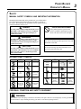
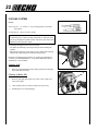
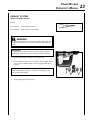
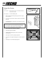
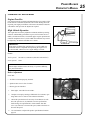
Power Blower
Operator's Manual
MODEL: PB-755H
PB-755T
WARNING
Read rules for safe operation and all instructions carefully. ECHO provides this Operator's Manual which must be read and understood for proper and safe operation.
X7531122402
X753002812
12/08
2
Introduction
Welcome to the ECHO family. This ECHO product was designed and manufactured to provide long life and on-thejob-dependability. Read and understand this manual. You will find it easy to use and full of helpful operating tips and
SAFETY messages.
the operator's manual
Read and understand this manual before operation. Keep it in a safe
place for future reference. It contains specifications and information
for operation, starting, stopping, maintenance, storage and assembly
specific to this product.
Table of Contents
Introduction.................................................................2
- The Operator's Manual........................................2
Safety..........................................................................3
Manual Safety Symbols and Important Information..3
- International Symbols..........................................3
- Personal Condition and Safety Equipment..........3
- Equipment............................................................6
Emission Control........................................................6
Description..................................................................7
Contents ................................................................... 11
Assembly..................................................................12
- Install Blower Pipes / Stick Handle PB-755H... 12
- Install Blower Pipes PB-755T...........................13
Operation................................................................... 14
- Fuel.................................................................... 14
- Starting Cold Engine.......................................... 16
- Starting Warm Engine........................................ 17
- Stopping Engine................................................. 17
- Operating Blower...............................................18
Maintenance..............................................................19
- Skill Levels........................................................ 19
- Maintenance Intervals........................................ 19
- Air Filter............................................................ 20
- Fuel Filter...........................................................21
- Spark Plug..........................................................21
- Cooling System..................................................22
- Exhaust System..................................................23
- Carburetor Adjustment.......................................25
Troubleshooting........................................................26
Storage......................................................................27
Specifications............................................................28
Servicing Information...............................................32
- Parts/Serial Number ............................................32
- Service...............................................................32
- ECHO Consumer Product Support....................32
- Warranty Card....................................................32
- Additional or Replacement Manuals.................32
Specifications, descriptions and illustrative material in this
literature are as accurate as known at the time of publication, but are subject to change without notice. Illustrations
may include optional equipment and accessories, and may
not include all standard equipment.
CopyRight© 2008 By Echo, Incorporated
All Rights Reserved.
Power Blower
Operator's Manual
Safety
manual safety symbols and important information
Throughout this manual and on the product itself, you will find safety
alerts and helpful, informational messages preceded by symbols or
key words. The following is an explanation of those symbols and key
words and what they mean to you.
DANGER
The safety alert symbol accompanied by the word
“DANGER” calls attention to an act or condition
which WILL lead to serious personal injury or
death if not avoided.
WARNING
The safety alert symbol accompanied by the word
“WARNING” calls attention to an act or condition which CAN lead to serious personal injury or
death if not avoided.
CAUTION
The safety alert symbol accompanied by the word
“CAUTION” calls attention to an act or condition
which may lead to minor or moderate personal
injury if not avoided.
Circle and slash symbol
This symbol means the specific action
shown is prohibited. Ignoring these prohibitions can result in serious or fatal injury.
NOTE
This enclosed message provides tips for use, care and
maintenance of the unit.
IMPORTANT
The enclosed message provides information necessary for the protection of the unit.
international symbols
Symbol form/shape
Symbol
description/application
Symbol form/shape
Read and understand
Operator's Manual.
Wear eyes, ears and
head protection
Hot
Surface
Safety/Alert
DO NOT allow
flames or sparks
near fuel.
Symbol
description/application
Symbol form/shape
Fuel and oil mixture
Finger Severing
Wear hand
protection. Use
two handed.
Wear slip resistant foot wear.
Symbol
description/application
Emergency stop
Symbol form/shape
Symbol
description/application
Ignition
ON/OFF
Carburetoradjustment
- Low speed mixture
Primer bulb
Carburetor adjustment
- Idle speed
Carburetor adjustment
- High speed mixture
Choke Control
"Cold Start"
Position
(Choke Closed)
Choke Control
"Run"
Position
(Choke Open)
DO NOT smoke
near fuel.
personal condition and safety equipment
WARNING
Power Blower users risk injury to themselves and others if the power blower is used improperly or safety precautions
are not followed. Proper clothing and safety gear must be worn when operating a blower.
3
4
Physical Condition
Your judgment and physical dexterity may not be good:
• if you are tired or sick,
• if you are taking medication,
• if you have taken alcohol or drugs.
Operate unit only if you are physically and mentally well.
Eye Protection
Wear eye protection that meets ANSI Z87.1 or CE requirements whenever you operate the unit.
Hand Protection
Wear no-slip, heavy-duty work gloves to improve your grip on the blower handle. Gloves also reduce the transmission
of machine vibration to your hands.
Breathing Protection
Wear a facemask to protect against dust.
Hearing Protection
ECHO recommends wearing hearing protection whenever unit is used.
Proper Clothing
Wear snug fitting, durable clothing;
• Pants should have long legs, shirts with long sleeves.
• DO NOT WEAR SHORTS,
• DO NOT WEAR TIES, SCARVES, and JEWELRY.
Wear sturdy work shoes with nonskid soles:
• DO NOT WEAR OPEN TOED SHOES,
• DO NOT OPERATE UNIT BAREFOOTED.
Keep long hair away from engine and blower intake. Retain hair with cap or net.
Hot Humid Weather
Heavy protective clothing can increase operator fatigue, which may lead to heat stroke. Schedule heavy work for early
morning or late afternoon hours when temperatures are cooler.
Vibration and Cold
It is believed that a condition called Raynaud’s Phenomenon, which affects the fingers of certain individuals, may be
brought about by exposure to vibration and cold. Exposure to vibration and cold may cause tingling and burning sensations, followed by loss of color and numbness in the fingers. The following precautions are strongly recommended,
because the minimum exposure, which might trigger the ailment, is unknown.
• Keep your body warm, especially the head, neck, feet, ankles,
hands, and wrists.
• Maintain good blood circulation by performing vigorous arm
exercises during frequent work breaks, and also by not smoking.
• Limit the hours of operation. Try to fill each day with jobs where
operating the unit or other hand-held power equipment is not
required.
• If you experience discomfort, redness, and swelling of the fingers
followed by whitening and loss of feeling, consult your physician
before further exposing yourself to cold and vibration.
Power Blower
Operator's Manual
Repetitive Stress Injuries
It is believed that overusing the muscles and tendons of the fingers, hands, arms, and shoulders may cause soreness,
swelling, numbness, weakness, and extreme pain in those areas. Certain repetitive hand activities may put you at a high
risk for developing a Repetitive Stress Injury (RSI). An extreme RSI condition is Carpal Tunnel Syndrome (CTS), which
could occur when your wrist swells and squeezes a vital nerve that runs through the area.
Some believe that prolonged exposure to vibration may contribute to CTS. CTS can cause severe pain for months or
even years.
To reduce the risk of RSI/CTS, do the following:
• Avoid using your wrist in a bent, extended, or twisted position.
Instead try to maintain a straight wrist position. Also, when
grasping, use your whole hand, not just the thumb and index
finger.
• Take periodic breaks to minimize repetition and rest your hands.
• Reduce the speed and force with which you do the repetitive
movement.
• Do exercises to strengthen the hand and arm muscles.
• Immediately stop using all power equipment and consult a doctor if you feel tingling, numbness, or pain in the fingers, hands,
wrists, or arms. The sooner RSI/CTS is diagnosed, the more
likely permanent nerve and muscle damage can be prevented.
danger
Do not operate this product indoors or in inadequately ventilated
areas. Engine exhaust contains poisonous emissions and can cause
serious injury or death.
Read the Manuals
• Provide all users of this equipment with the Operator’s Manual
and Safety Manual for instructions on Safe Operation.
Clear the Work Area
• Spectators and fellow workers must be warned, and children and
animals prevented from coming nearer than 15 m (50 ft.) while
the unit is in use.
• Take wind conditions into account: avoid open doors and windows.
• Do not point blower at people or animals.
Keep a Firm Grip
• Hold the front and rear handles with both hands, with thumbs
and fingers encircling the handles.
Keep a Solid Stance
• Maintain footing and balance at all times. Do not stand on slippery, uneven or unstable surfaces. Do not work in odd positions
or on ladders. Do not over reach.
Avoid Hot Surfaces
• Keep exhaust area clear of flammable debris. Avoid contact during and immediately after operation.
5
6
equipment check
WARNING
Use only ECHO approved attachments. Serious injury may result from the use of a non-approved attachment combination. ECHO, INC. will not be responsible for the failure of cutting devices, attachments or accessories which have
not been tested and approved by ECHO. Read and comply with all safety instructions listed in this manual and safety
manual.
•
•
•
•
Check unit for loose/missing nuts, bolts and screws. Tighten and/or replace as needed.
Do not use blower if any part is missing or damaged.
Have repairs done only by an authorized ECHO Service dealer.
Do not use any attachment, accessory or replacement part unless it is recommended in this Operator's Manual.
WARNING
Moving parts can amputate fingers or cause severe injuries. Keep hands, clothing and loose objects away from all
openings.
•ALWAYS stop engine, disconnect spark plug, and make sure all moving parts have come to a complete stop before removing obstructions, clearing debris, or servicing unit.
•DO NOT start or operate unit unless all guards and protective covers are properly assembled to unit.
•NEVER reach into any opening while the engine is running. Moving parts may not be visible through openings.
WARNINg
Check fuel system for leaks due to fuel tank damage, especially if the unit is dropped. If damage or leaks are found,
do not use unit, otherwise serious personal injury or property damage may occur. Have unit repaired by an authorized
servicing dealer before using.
Emission Control (exhaust & evaporative)
EPA Phase 2 / C.A.R.B. TIER III
The emission control system for the engine is EM/TWC (Engine Modification and 3-way Catalyst) and for the fuel tank
the Control System is EVAP (Evaporative Emissions) or N (for nylon tank). Evaporative emission may be applicable to
California models only.
IMPORTANT ENGINE INFORMATION
ENGINE FAMILY: 7EHXS.0635KB DISPLACEMENT: 63.3 cc
EMISSION COMPLIANCE PERIOD : 300 HRS.
THIS ENGINE MEETS U.S. EPA PH2 EXH AND 2007 AND
LATER CALIFORNIA EXH AND EVAP EMISSION REGULATIONS FOR S.O.R.E. REFER TO OWNER'S MANUAL FOR
MAINTENANCE SPECIFICATIONS AND ADJUSTMENTS.
An Emission Control Label is located on the unit. (This is an EXAMPLE ONLY, information on label varies by engine
FAMILY).
PRODUCT EMISSION DURABILITY (EMISSION COMPLIANCE PERIOD)
The 300 hour emission compliance period is the time span selected by the manufacturer certifying the engine emissions output meets applicable emissions regulations, provided that approved maintenance procedures are followed as
listed in the Maintenance Section of this manual.
Power Blower
Operator's Manual
Description
PB-755H
Locate these safety decals on your unit. Make sure the decals are legible and that you understand and follow the instructions on them. If a decal cannot be read, a new one can be ordered from your ECHO dealer. See PARTS ORDERING
instructions for specific information.
Hot Decal (near muffler)
1
11
2
3
P/N 89016006361
10
4
7
12
9
13
8
5
14
6
General Warning Decal (located on top of blower housing)
P/N 89016009461
Sound Label (located on blower housing)
dB(A)
74 Category III
Measured at 50 ft. (15m) per ANSI B175.2
P/N X508000180
7
8
1. AIR CLEANER - Contains replaceable air filter element.
2. SPARK PLUG - Provides spark to ignite fuel mixture.
3. SAFETY DECAL - Lists important safety precautions.
4. SPARK ARRESTOR - CATALYTIC MUFFLER / MUFFLER - The muffler or catalytic muffler controls
exhaust noise and emission. The spark arrestor screen prevents hot, glowing particles of carbon from leaving the
muffler. Keep exhaust area clear of flammable debris.
5. CHOKE - Move lever up to "Cold Start" (
Run position (
) starting position and for emergency stopping. Move lever down to
).
6. PURGE BULB - Pumping purge bulb before starting engine draws fresh fuel from the fuel tank, purging air from
the carburetor. Pump purge bulb until fuel is visible and flows freely in the clear fuel tank return line. Pump purge
bulb an additional 4 or 5 times.
7. RECOIL STARTER HANDLE - Pull recoil handle slowly until starter engages, then quickly and firmly. When
engine starts, return handle slowly. DO NOT let handle snap back or damage to unit will occur.
8. FUEL TANK - Contains fuel and fuel filter.
9. FUEL TANK CAP - Covers and seals fuel tank.
10. HANDLE - Rotates downward for throttle control access. Spring loaded for flexible operation.
11. BLOWER PIPES - Exclusive positive locking system.
12. SHOULDER HARNESS - Used to support unit on operator's back. The straps are adjustable.
13. THROTTLE POSITION LEVER/STOP SWITCH - Combination stop switch and variable speed throttle lever.
When the lever is moved all the way forward the blower is at Wide Open Throttle (W.O.T.). When the lever is
moved rearward to detent, the blower is at idle. When the lever is moved rearward past the idle detent the blower
will stop.
1 4. STICK HANDLE - Provides comfortable grip for directing air flow.
Power Blower
Operator's Manual
PB-755T
Locate these safety decals on your unit. Make sure the decals are legible and that you understand and follow the instructions on them. If a decal cannot be read, a new one can be ordered from your ECHO dealer. See PARTS ORDERING
instructions for specific information.
1
Hot Decal (near muffler)
12
11
2
3
P/N 89016006361
4
10
5
13
9
8
6
14
15
7
16
17
General Warning Decal (located on top of blower housing)
P/N 89016009461
Sound Label (located on blower housing)
dB(A)
74 Category III
Measured at 50 ft. (15m) per ANSI B175.2
P/N X508000180
9
10
1. AIR CLEANER - Contains replaceable air filter element.
2. SPARK PLUG - Provides spark to ignite fuel mixture.
3. SAFETY DECAL - Lists important safety precautions.
4. SPARK ARRESTOR - CATALYTIC MUFFLER / MUFFLER - The muffler or catalytic muffler controls
exhaust noise and emission. The spark arrestor screen prevents hot, glowing particles of carbon from leaving the
muffler. Keep exhaust area clear of flammable debris.
5. RECOIL STARTER HANDLE - Pull recoil handle slowly until starter engages, then quickly and firmly. When
engine starts, return handle slowly. DO NOT let handle snap back or damage to unit will occur.
6. CHOKE - Move lever up to "Cold Start" (
Run position (
) starting position and for emergency stopping. Move lever down to
).
7. PURGE BULB - Pumping purge bulb before starting engine draws fresh fuel from the fuel tank, purging air from
the carburetor. Pump purge bulb until fuel is visible and flows freely in the clear fuel tank return line. Pump purge
bulb an additional 4 or 5 times.
8. FUEL TANK - Contains fuel and fuel filter.
9. FUEL TANK CAP - Covers and seals fuel tank.
10. BLOWER PIPES - Exclusive positive locking system.
11. THROTTLE POSITION LEVER - Pull back to increase engine speed. Friction washers maintain throttle lever
setting.
12. STOP SWITCH - Slide switch mounted on top of handle. Move forward to run, back to stop.
13. SHOULDER HARNESS - Used to support unit on operator's back. The straps are adjustable.
14. HANDLE - Used by operator to direct and control air flow.
15. THROTTLE TRIGGER - Spring loaded to return to idle when released. During acceleration, press trigger gradually for best operating technique.
16. LOCKING KNOB - Allows operator to adjust handle position for optimum comfort and control.
17. FLEXIBLE PIPE - Allows for full range of movement.
Power Blower
Operator's Manual
Contents
PB-755H
___
___
___
___
___
___
___
___
___
___
___
___
___
___
___
1 - Power Head
1 - Flex Pipe
1 - Pipe w/swivel
1 - Straight Pipe
1 - Straight Pipe
1 - Operator's Manual
1 - Warranty Registration Card
1 - ECHO Emissions and Warranty Statement
1 - Plastic Bag
2 - Clamps w/screws
1 - Stick Handle
1 - Bolt 6x45
1 - Washer 6
1 - Wing nut
1 - Echo Power Blend X TM 2-stroke oil sample
PB-755T
___
___
___
___
___
___
___
___
___
___
___
___
1 - Power Head
1 - Flex Pipe
1 - Pipe w/swivel
1 - Straight Pipe
1 - Straight Pipe
1 - Operator's Manual
1 - Warranty Registration Card
1 - ECHO Emissions and Warranty Statement
1 - Plastic Bag
2 - Clamps w/screws
1 - Guide Loop
1 - Echo Power Blend X TM 2-stroke oil sample
11
12
Assembly
PB-755H
WARNING
Never perform maintenance or assembly procedures with engine
running or serious personal injury may result.
install blower pipes
/ stick handle
1. Assemble clamps (A) onto both ends of flexible pipe (B).
A
A
B
2. Assemble swivel pipe (C) into flexible pipe (B) and tighten clamp
(A).
B
3. Assemble flexible pipe (B) to elbow (D) on blower and tighten
clamp (A).
NOTE
A light lubricant may be used to ease assembly of flexible pipe to
blower elbow.
C
D
4. Loosen wing nut (E) completely and open stick handle clamp.
G
H
5. Align notches (F) in handle clamp with tabs (G).
F
6. Slide stick handle onto swivel pipe (C). Stick handle should be
angled away from operator.
E
7. Position stick handle (H) for comfortable operation, and tighten
wing nut (E).
8. Assemble straight pipe (I) onto swivel pipe (C), until you feel
light resistance. Do not force connection. Hold swivel pipe and
turn straight pipe clockwise, engaging positive locking channels,
until connection is firm. Do not force connection.
G
C
I
9. Assemble straight pipe with decal (J) to straight pipe (I) as in step
8.
NOTE
Blower use will eventually loosen pipe connections. Exclusive
positive locking system allows pipes to be tightened. If loosening
occurs, remove two straight pipes and install according to instructions 8 & 9.
J
Power Blower
Operator's Manual
13
PB-755T
G
G
WARNING
Never perform maintenance or assembly procedures with engine
running or serious personal injury may result.
install blower pipes
B
G
A
A
1. Place guide loop (G) across elbow clamp, and turn until clips
fully engage clamp band.
2. Assemble clamps (A) onto both ends of flexible pipe (B).
NOTE
Clamp with cable guide loop (G) fits elbow end of flexible pipe.
3. Assemble swivel pipe (C) into flexible pipe (B).
B
E
F
NOTE
Assure throttle cable is not twisted before installing handle (E).
D
C
H
4. Position cable between the elbow (D) and frame and along the top
of the flexible pipe. Loosen knob (H) on handle (E). Align notch
in handle with tabs (F). Install onto swivel pipe (C) past long
ridges in pipe.
5. Assemble flexible pipe (B) to elbow (D) on blower and tighten
clamps (A). Position guide loop (G) on inside (blower side) of
flexible tube.
G
E
NOTE
A light lubricant may be used to ease assembly of flexible pipe to
blower elbow.
H
6. Clip throttle cable into throttle cable guide loop (G).
7. Move handle (E) to desired position. Tighten knob (H) hand tight.
8. Assemble straight pipe (I) onto swivel pipe (C), until you feel
light resistance. Do not force connection. Hold swivel pipe and
turn straight pipe clockwise, engaging positive locking channels,
until connection is firm. Do not force connection.
9. Assemble straight pipe with decal (J) to straight pipe (I) as in step
8.
NOTE
Blower use will eventually loosen pipe connections. Exclusive
positive locking system allows pipes to be tightened. If loosening
occurs, remove two straight pipes and install according to instructions 8 & 9.
J
E
I
C
14
Operation
WARNING
Moving parts can amputate fingers or cause severe injuries. Keep hands, clothing and loose objects away from all
openings. Always stop engine, disconnect spark plug, and make sure all moving parts have come to a complete stop
before removing obstructions, clearing debris, or servicing unit. Blower housing may contain shredder blades and
other sharp edges that can cause serious injuries if touched, even if engine is off and blades are not moving. Wear
gloves to protect hands from sharp edges and hot surfaces.
fuel
NOTICE: Use of unmixed, improperly mixed, or fuel older than 90 days, (stale fuel), may cause hard starting, poor
performance, or severe engine damage and void the product warranty. Read and follow instructions in the Storage
section of this manual.
WARNING
Alternative fuels, such as E-20 (20% ethanol), E-85 (85% ethanol) or any fuels not meeting ECHO requirements are
NOT approved for use in ECHO 2-stroke gasoline engines. Use of alternative fuels may cause performance problems, loss of power, overheating, fuel vapor lock, and unintended machine operation, including, but not limited to,
improper clutch engagement. Alternative fuels may also cause premature deterioration of fuel lines, gaskets, carburetors and other engine components.
Fuel Requirements
Gasoline - Use 89 Octane [R+M/2] (mid grade or higher) gasoline known to be good quality. Gasoline may contain up to
10% Ethanol (grain alcohol) or 15% MTBE (methyl tertiary-butyl ether). Gasoline containing methanol (wood alcohol)
is NOT approved.
Two Stroke Oil - A two-stroke engine oil meeting ISO-L-EGD (ISO/CD 13738) and JASO M345/FC/FD Standards
must be used. ECHO brand premium Power Blend X TM Universal 2-Stroke Oil meets these standards. Engine problems
due to inadequate lubrication caused by failure to use an ISO-L-EGD (ISO/CD 13738) and JASO M345/FC/FD certified
oil, such as ECHO premium Power Blend X TM, will void the two-stroke engine warranty.
IMPORTANT
Echo premium Power Blend X TM Universal 2-Stroke Oil may be mixed at 50:1 ratio for application in all Echo engines sold in the past regardless of ratio specified in those manuals.
Power Blower
Operator's Manual
Handling Fuel
DANGER
Fuel is VERY flammable. Use extreme care when mixing, storing or handling or serious personal injury may result.
•Use an approved fuel container.
•DO NOT smoke near fuel.
•DO NOT allow flames or sparks near fuel.
•Fuel tanks/cans may be under pressure. Always loosen fuel caps slowly allowing pressure to equalize.
•NEVER refuel a unit when the engine is HOT or RUNNING!
•DO NOT fill fuel tanks indoors. ALWAYS fill fuel tanks outdoors over bare ground.
• DO NOT overfill fuel tank. Wipe up spills immediately.
•Securely tighten fuel tank cap and close fuel container after refueling.
•Inspect for fuel leakage. If fuel leakage is found, do not start or operate unit until leakage is repaired.
•Move at least 3m (10 ft.) from refueling location before starting the engine.
Mixing Instructions
1. Fill an approved fuel container with half of the required amount
of gasoline.
2. Add the proper amount of 2-stroke oil to gasoline.
3. Close container and shake to mix oil with gasoline.
4. Add remaining gasoline, close fuel container, and remix.
IMPORTANT
Spilled fuel is a leading cause of hydrocarbon emissions. Some
states may require the use of automatic fuel shut-off containers
to reduce fuel spillage.
After use
• DO NOT store a unit with fuel in its tank. Leaks can occur. Return
unused fuel to an approved fuel storage container.
Storage - Fuel storage laws vary by locality. Contact your local government for the laws affecting your area. As a precaution, store fuel in
an approved, airtight container. Store in a well-ventilated, unoccupied
building, away from sparks and flames.
IMPORTANT
Stored fuel ages. Do not mix more fuel than you expect to use in
thirty (30) days, ninety (90) days when a fuel stabilizer is added.
IMPORTANT
Stored two-stroke fuel may separate. ALWAYS shake fuel container thoroughly before each use.
15
16
starting cold engine
• Recoil starter: Use short pulls - only 1/2-2/3 of rope length for starting. Do not allow the rope to snap back in. Always hold the unit
firmly.
PB-755H
PB-755H
A
1. Throttle Lever
Move throttle lever (A) to IDLE DETENT position.
PB-755T
1. Throttle Lever/Stop Switch
Move throttle lever (A) forward to idle position. Slide stop switch
(B) forward to run position.
PB-755T
PB-755H, PB-755T
2. Choke
Move choke (C) up to "Cold Start" position (
).
3. Purge Bulb
Pump purge bulb (D) until fuel is visible and flows freely in the
clear fuel tank return line. Pump bulb an additional 4 or 5 times.
C
4. Recoil Starter
Pull recoil starter handle (E) until engine fires (5 or 6 pulls maximum).
D
5. Choke
Move choke (C) down to run position (
restart engine.
), and if necessary,
NOTE
If engine does not start after 5 pulls, move choke to "Cold Start"
position, and repeat steps 4 & 5.
NOTE
Allow engine to warm up before use.
B
A
C
E
Power Blower
Operator's Manual
starting warm engine
PB-755H
PB-755H
A
1. Throttle Lever
Move throttle lever (A) to IDLE DETENT position.
PB-755T
1. Throttle Lever/Stop Switch
Move throttle lever (A) forward to idle position. Slide stop
switch (B) forward to run position.
PB-755T
B
A
PB-755H, PB-755T
2. Recoil Starter
Pull recoil starter handle (E) and engine should start. Do not use
choke (C).
NOTE
If engine does not start after 5 pulls, use cold start procedures.
C
E
stopping engine
PB-755H
1. Throttle Lever
Move throttle lever (A) to idle detent position and allow engine to
return to idle before shutting off engine.
2. Move throttle lever (A) to "O" (Stop) position.
A
PB-755H
PB-755T
1. Throttle Trigger/Throttle Position Lever
Release throttle trigger (C). Move throttle position lever (A)
forward to idle position and allow engine to return to idle before
shutting engine off.
2. Stop Switch
Slide stop switch (B) to Stop position.
B
PB-755T
A
WARNING
If engine does not stop when stop switch is moved to STOP position, close choke - COLD START position - to stall engine. Have
your ECHO dealer repair stop switch before using blower again.
C
17
18
operating blower
WARNING
Engine exhaust IS HOT, and contains Carbon Monoxide (CO),
a poison gas. Breathing CO can cause unconsciousness, serious
injury, or death. Exhaust can cause serious burns. ALWAYS blow
exhaust away from your face and body.
WARNING
Always wear safety glasses, hearing protection, a face filter mask and
take all safety precautions or serious personal injury may result.
Do not point the blower pipe in the direction of people or pets.
Read the Safety Section on pages 4 - 6 carefully.
PB-755H
IMPORTANT
To avoid engine damage due to over-revving, do not block blower
pipe opening.
1. Use only during appropriate hours.
2. Allow the engine to warm up at a fast idle for a few minutes.
3.
PB-755H
Set engine speed with throttle lever (A).
PB-755T
Control engine speed with throttle trigger (C), or throttle position
lever (A). Rotate throttle position lever forward for lower speed,
back for higher speed.
4. Use lower speed to blow dry leaves from walks, patios and drives.
5. Additional speed may be necessary to clean grass and leaves from a
lawn or flower bed.
6. Higher speed may be necessary to move gravel, dirt, snow, bottles
or cans from a driveway, street, parking lot or stadium.
NOTE
Never use a higher speed setting than necessary to perform a task.
Remember, the higher the engine speed, the louder the blower noise.
Minimize dust by using blower at lower speeds and by dampening material with water/mist when necessary. Keep debris on your
property.
Be Smart - be a good neighbor.
PB-755T
A
C
A
Power Blower
Operator's Manual
19
Maintenance
WARNING
Moving parts can amputate fingers or cause severe injuries. Keep hands, clothing and loose objects away from all
openings. Always stop engine, disconnect spark plug, and make sure all moving parts have come to a complete stop
before removing obstructions, clearing debris, or servicing unit. Allow unit to cool before performing service. Wear
gloves to protect hands from sharp edges and hot surfaces.
Your ECHO blower is designed to provide many hours of trouble free service. Regular scheduled maintenance will help
your blower achieve that goal. If you are unsure or are not equipped with the necessary tools, you may want to take your
unit to an ECHO Service Dealer for maintenance. To help you decide whether you want to DO-IT-YOURSELF or have
the ECHO Dealer do it, each maintenance task has been graded. If task is not listed, see your ECHO Dealer for repairs.
skill level
Level 1 =
Level 2 =
Easy to do. Common tools may be required.
Moderate difficulty. Some specialized tools may be required.
ECHO offers REPOWERTM Maintenance Kits and Parts to make your maintenance job easier.
maintenance intervals
COMPONENT / SYSTEM
MAINTENANCE
PROCEDURE
REQ'D
SKILL
LEVEL
DAILY OR
BEFORE USE
EVERY
REFUEL
3 MONTHS
YEARLY
OR 90
600 HOURS
HOURS
Air Filter
Inspect/Clean
1
I/C*
Choke Shutter
Inspect/Clean
1
I/C
Fuel Filter
Inspect/Replace
1
I *
Fuel Cap Gasket
Inspect/Replace
1
I *
Fuel System
Inspect/Replace
1
Spark Plug
Inspect/Clean/Replace
1
Cooling System
Inspect/Clean
2
Muffler Spark Arrestor
Inspect/Clean/Replace
2
I/C/R*
Cylinder Exhaust Port
Inspect/Clean/Decarbon
2
I/C
Recoil Starter Rope
Inspect/Clean
1
I/C*
Screws/Nuts/Bolts
Inspect/Tighten/Replace
1
I *
I (1) *
R*
I/R*
I (1) *
I/C/R*
I/C
MAINTENANCE PROCEDURE LETTER CODES: I = INSPECT, R = REPLACE, C = CLEAN
IMPORTANT NOTE - Time intervals shown are maximum. Actual use and your experience will determine the
frequency of required maintenance.
MAINTENANCE PROCEDURE NOTES:
(1) Low evaporative fuel tanks DO NOT require regular maintenance to maintain emission integrity.
* All recommendations to replace are based on the finding of damage or wear during inspection.
20
air filter
Level 1.
Tools required: 25 - 50mm (1 - 2 in.) cleaning brush
Parts required: Tune Up Kit
NOTE
Always brush dirt and debris away from air cleaner area prior to
cleaning air filter.
1. Brush dirt off air cleaner area. Keep dirt away from engine and
air intake grid.
2. Remove air filter cover. Brush dirt from inside cover and away
from edges of air filter.
3. Check air filter seal for tight fit with air filter case.
4. Remove air filter from case. Use care to prevent dirt and debris
from falling into air filter case.
5. Inspect filter element and seal. Replace filter if any of these problems are present:
•Air filter seal does not fit tightly against case
•Air filter seal is distorted, worn, or damaged
•Air filter element has holes or other damage
•Air filter element is saturated with dirt
•Air filter element is soaked with fuel mix
6. If air filter is in good condition and can be cleaned and reused,
lightly brush debris from air filter element, or blow filter element
clean using low pressure (40 psi or less) compressed air directed
at inside of filter.
IMPORTANT
When using compressed air, always direct air stream at inside surface of filter so dust and debris will be blown out of filter. Keep air
nozzle 6 - 8 inches away from filter to prevent damage to filter.
7. Install air filter in case, and replace cover.
NOTICE
Actual replacement interval for air filter depends on operating conditions. Operation in dustier applications requires more frequent
cleaning and replacement. Continued operation with a damaged
or excessively dirty filter will allow dirt and debris to enter engine,
and result in poor performance, rapid engine wear, and premature
engine failure.
Power Blower
Operator's Manual
fuel filter
Level 1.
Tools required: 200 - 250 mm (8 - 10 in.) length of wire with one end bent into a hook, clean rag, funnel, and an approved fuel container
Parts required: RepowerTM Tune Up Kit
DANGER
Fuel is VERY flammable. Use extreme care when mixing, storing
or handling.
1. Use a clean rag to remove loose dirt from around fuel cap and empty fuel tank.
2. Use the “fuel line hook” to pull the fuel line and filter from the tank.
3. Remove the filter from the line and install the new filter.
spark plug
Level 1.
Tools required: 19mm Spark Plug deep socket, Feeler gauge Parts Required: RepowerTM Tune Up Kit
IMPORTANT
Use only NGK BPM-8Y spark plug (BPMR-8Y in Canada)
otherwise severe engine damage may occur.
1. Remove spark plug , and check for fouling, worn and rounded
center electrode.
2. Clean the plug or replace with a new one. DO NOT sand blast to
clean. Remaining sand will damage engine.
3. Adjust spark plug gap by bending outer electrode.
4. Tighten spark plug to 150-170 kgf • cm (130-150 in • lbf).
0.65 mm
(0.026 in.)
21
22
cooling system
Level 2.
Tools required: 25 - 50mm (1 - 2 in.) cleaning brush, Cross Head Screwdriver
Parts Required: None, if you are careful.
I MPORTANT
To maintain proper engine operating temperatures, cooling air must
pass freely through the cylinder fin area. This flow of air carries combustion heat away from the engine.
Overheating and engine seizure can occur when:
• Air intakes are blocked, preventing cooling air from reaching the cylinder.
• Dust and grass build up on the outside of the cylinder. This build up insulates the engine and prevents the heat from leaving.
Removal of cooling passage blockages or cleaning of cooling fins is
considered “Normal Maintenance.” Any failure attributed to lack of
maintenance is not warranted.
Cleaning Grill
1. Remove accumulated debris from intake grill between backpack
frame and blower housing.
Cleaning Cylinder Fins
1. Remove spark plug and engine cover (four screws), pull cover
away from engine.
2. Clean cylinder fins (A) to allow cooling air to pass freely.
3. Install engine cover and spark plug.
A
Power Blower
Operator's Manual
23
exhaust system
Spark Arrestor Screen
Level 2.
Tools required: Cross Head Screwdriver
Parts Required: Spark arrestor screen, Gaskets
WARNING
Do not perform maintenance on engine or muffler until engine and
muffler are completely cool, otherwise serious personal injury may
result.
IMPORTANT
Carbon deposits in muffler will cause a drop in engine output and
overheating. Spark arrestor screen must be checked periodically.
1. Remove spark plug and engine cover (four screws).
2. Remove spark arrestor covers (A), gaskets (B), and spark arrestor
screen (C) from muffler. Replace screen if plugged with carbon
deposits.
NOTE
When cleaning carbon deposit, be careful not to damage the catalytic element inside muffler.
3. Install spark arrestor screen and cover.
4. Install spark plug and engine cover.
C
B
A
24
Exhaust Port Cleaning
Level 2
Tools required: Wood or plastic scraper, Cross Head Screwdriver, 4 & 5mm Hex Wrench
Parts Required: As needed: Muffler gasket
1. Remove spark plug lead from spark plug, and remove engine
cover (5 screws).
2. Place piston at top dead center. Remove muffler (A) and muffler
gasket (B ).
3. Use a wood or plastic scraping tool to clean deposits from cylinder exhaust port.
IMPORTANT
Never use a metal tool to scrape carbon from the exhaust port.
Do not scratch the cylinder or piston when cleaning the exhaust
port. Do not allow carbon particles to enter the cylinder.
4. Inspect muffler gasket, and replace if damaged.
5. Install muffler gasket and muffler.
6. Tighten muffler mounting bolts (or nuts) to 80-95 in•lbf (90-110 kgf•cm).
7. Start engine, and warm to operating temperature.
8. Stop engine, and re-tighten mounting bolts (or nuts) to specifications.
9. Install engine cover and attach spark plug lead.
Power Blower
Operator's Manual
carburetor adjustment
Engine Break-In
New engines must be operated a minimum duration of two tanks of fuel
break-in before carburetor adjustments can be made. During the breakin period your engine performance will increase and exhaust emissions
will stabilize. Idle speed can be adjusted as required.
High Altitude Operation
This engine has been factory adjusted to maintain satisfactory starting,
emission, and durability performance up to 1,100 feet mean sea level
(MSL) (96.0 kPa and below). To maintain proper engine operation and
emission compliance above 1,100 feet MSL the carburetor may need to
be adjusted by an authorized ECHO service dealer.
Important
If the engine is adjusted for operation above 1,100 feet MSL, the
carburetor must be re-adjusted when operating the engine below
1,100 feet MSL, otherwise severe engine damage can result.
Level 2.
Tools required: Screwdriver, tachometer (Echo P/N 99051130017)
Parts required: None.
NOTE
Do not adjust carburetor unless necessary. If you have difficulty,
see your ECHO dealer.
Before Adjustment
Check that:
• Air filter is clean and properly installed.
• Spark arrestor screen is free of carbon.
• Blower pipes are installed.
1. Start engine, run at idle for one minute.
2. Complete warm up by running at full throttle for 5 minutes, operating choke twice to clear air from carburetor chambers.
3. Check idle speed and reset if necessary. If a tachometer is available, idle speed screw (A) should be set to the specifications
found on Page 28 "Specifications" of this manual. Turn idle
screw (A) clockwise to increase idle speed; counter clockwise to
decrease idle speed.
4. Use a tachometer to adjust idle speed to specifications found on
page 28.
A
25
26
Troubleshooting
TROUBleSHOOTING CHART
Problem
Engine cranks starts hard/
doesn't
start
C h eck
Status
Fuel at carburetor
No fuel at carburetor
Fuel at cylinder
C au se
Remedy
Fuel strainer clogged
Fuel line clogged
Carburetor
Clean or replace
Clean or replace
See your Echo dealer
No fuel at cylinder
Carburetor
See your Echo dealer
Muffler wet with fuel
Fuel Mixture too rich
Open choke
Clean/replace air filter
Adjust carburetor
See your Echo dealer
Spark at end
of plug wire
No spark
Stop switch off
Electrical problem
Interlock switch
Turn switch to ON
See your Echo dealer
See your Echo dealer
Spark at plug
No spark
Spark gap incorrect
Covered with carbon
Fouled with fuel
Plug defective
Adjust to .65mm (0.026 in.)
Clean or replace
Clean or replace
Replace plug
Air filter
Air filter dirty
Normal wear
Clean or replace
Fuel filter
Fuel filter dirty
Contaminants/residues in
fuel
Replace
Fuel vent
Fuel vent plugged
Spark Plug
Plug dirty/worn
Carburetor
Improper adjustment
Cooling System
Cooling system
dirty/plugged
Spark Arrestor Screen
Spark arrestor screen
plugged
Engine does
not crank
N/A
N/A
Engine runs,
blower doesn't
work or is
weak/uneven
Blower pipe
Pipe clogged
Engine runs,
but dies or
does not
accelerate
properly
DANGER
Pipe loose
Pipe damaged
Contaminants/residues in fuel Clean or replace
Normal wear
Clean and adjust or replace
Vibration
Adjust
Extended operation in
dirty/dusty locations
Clean
Normal wear
Replace
Internal engine problem
See your Echo dealer
Build-up of debris
Unclog
Vibration
Tighten
Wear/Misuse
Replace
Fuel vapors are extremely flammable and may cause fire and/or explosion. Never test for ignition spark by grounding spark plug near cylinder plug hole, otherwise serious personal injury may result.
Power Blower
Operator's Manual
Storage
warning
During operation the muffler or catalytic muffler and surrounding cover become hot. Always keep exhaust area clear
of flammable debris during transportation or when storing, otherwise serious property damage or personal injury may
result.
Long Term Storage (Over 30 Days)
Do not store your unit for a prolonged period of time (30 days or longer) without performing protective storage maintenance which includes the following:
1. Store unit in a dry, dust free place, out of the reach of children.
DANGER
Do not store in enclosure where fuel fumes may accumulate or reach an open flame or spark.
2. Place the stop switch in the "STOP" position.
3. Remove accumulation of grease, oil, dirt and debris
from exterior of unit.
4. Perform all periodic lubrication and services that are
required.
5. Tighten all screws and nuts.
6. Drain the fuel tank completely and pull the recoil
starter handle several times to remove fuel from the
carburetor.
7. Remove the spark plug and pour 7cc (1/4 oz.) of
fresh, clean ECHO 2-stroke engine oil into the cylinder through the spark plug hole.
A.Place a clean cloth over the spark plug hole.
B.Pull the recoil starter handle 2-3 times to
distribute the oil inside the engine.
C.Observe the piston location through the spark plug hole. Pull the recoil handle slowly until the piston reaches the top of its travel and leave it there.
8. Install the spark plug (do not connect ignition cable).
9. Remove blower pipe assembly from unit.
27
28
Specifications
MODEL���������������������������������������������������� PB-755H, PB-755T
Length ������������������������������������������������������ 375 mm (14.8 in.)
Width�������������������������������������������������������� 485 mm (19 in.)
Height������������������������������������������������������� 527 mm (20.8 in.)
Weight (dry) (PB-755H)��������������������������������� 11.8 kg (26.2 lb.)
Weight (dry) (PB-755T)���������������������������������� 11.8 kg (26.2 lb.)
Engine Type������������������������������������������������ Air cooled, two-stroke, single cylinder gasoline engine
Displacement����������������������������������������������� 63.3 cc (3.86 cu. in.)
Bore���������������������������������������������������������� 48.0 mm (1.89 in.)
Stroke�������������������������������������������������������� 35.0 mm (1.38 in.)
Carburetor�������������������������������������������������� Walbro w/primer bulb
Ignition System�������������������������������������������� Flywheel Magneto, capacitor discharge ignition type
Spark Plug�������������������������������������������������� NGK BPM-8Y Gap 0.65 mm (0.026 in.)
Exhaust System�������������������������������������������� Spark Arrestor - Catalytic Muffler / Muffler
Fuel���������������������������������������������������������� Mixed (Gasoline and Two-stroke Oil)
Fuel/Oil Ratio���������������������������������������������� 50 : 1 Power Blend X TM ISO-L-EGD (ISO/CD 13738) and
J.A.S.O. M345- FC/FD, two-stroke, air-cooled engine oil.
Gasoline����������������������������������������������������� Use 89 Octane unleaded. Do not use fuel containing methyl
alcohol, more than 10% ethyl alcohol or 15% MTBE. Do not use
alternative fuels such as E-20 or E-85.
Oil������������������������������������������������������������ Power Blend X TM Premium Universal 2-Stroke Oil
Fuel Tank Capacity���������������������������������������� 2.0 lit. (67.7 US fl. oz.)
Recoil Starter System������������������������������������� Automatic Recoil Starter Centrifugal Type
Idle Speed �������������������������������������������������� 2400 - 3200 (RPM)
Wide Open Throttle Speed ������������������������������� 6800 - 7300 (RPM)
Maximum Air Speed (Measured at pipe end)��������� 329.9 KM/H (205 mph)
Average Air Volume (Measured at pipe end)���������� 17.6 m3/min. (620 cu. ft./min.)
Sound Level at 50 ft. dB(A) scale per ANSI B175.2� 74 dB(A)
Power Blower
Operator's Manual
notes
29
30
notes
Power Blower
Operator's Manual
notes
31
Servicing Information
parts/serial number
Genuine ECHO Parts and ECHO REPOWER™ Parts and Assemblies
for your ECHO products are available only from an Authorized ECHO
Dealer. When you do need to buy parts always have the Model Number, Type and Serial Number of the unit with you. You can find these
numbers on the engine housing. For future reference, write them in the
space provided below.
Model No. _____________ Type _________SN. ______________
service
DEALER?
Call
1-800-432-ECHO
Service of this product during the warranty period must be performed
by an Authorized ECHO Service Dealer. For the name and address of
the Authorized ECHO Service Dealer nearest you, ask your retailer or
call: 1-800-432-ECHO (3246). Dealer information is also available on
our Web Site. When presenting your unit for Warranty service/repairs,
proof of purchase is required.
1-800-432-3246
or
www.echo-usa.com
echo consumer product support
If you require assistance or have questions concerning the application, operation or maintenance of this product you may call the ECHO
Consumer Product Support Department at 1-800-673-1558 from 8:30
am to 4:30 pm (Central Standard Time) Monday through Friday. Before
calling, please know the model and serial number of your unit to help
your Consumer Product Support Representative.
CONSUMER PRODUCT
SUPPORT
1-800-673-1558
8:30 - 4:30 Mon - Fri C.S.T.
warranty registration
To ensure trouble free warranty coverage it is important that you register your Echo equipment on-line at www.echo-usa.com. Other registration options are by automated phone at 1-800-432-3246 or by filling
out the warranty registration card supplied with your unit. Registering
your product confirms your warranty coverage and provides a direct
link between you and ECHO if we find it necessary to contact you.
additional or replacement manuals
Safety Manuals in English/Spanish or English/French are available, free of charge, from your ECHO dealer or at www.
echo-usa.com.
Operator's and Parts Manuals are available by:
• Downloading free from www.echo-usa.com
• Purchasing from your Echo Dealer.
• Manuals are available by sending a written request stating the model number and serial number of your Echo unit, part
number of the manual, your name and address, and mail to the address below.
Safety Videos are available from your Echo dealer. A $5.00 shipping charge will be required for each video.
ECHO, INCORPORATED
(H) P08511001001/P08511999999
(H) P10012001001/P10012999999
400 Oakwood Road
Lake Zurich, IL 60047
www.echo-usa.com
(T) P08611001001/P08611999999
(T) P10812001001/P10812999999