1
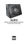
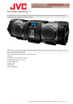
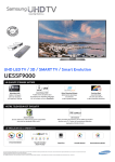
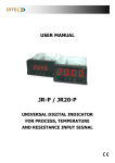
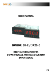
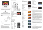
MXC22
INSTALLATION/OWNER’S MANUAL
AM/FM/Cassette Marine Receiver
MARINE
®
®
MXC22 INSTALLATION
Preparation
Please read entire manual before installation.
Before You Start
• Disconnect negative battery terminal.
(consult a qualified technician for instructions)
• Avoid installing the unit where it would be subject to high temperatures,
such as from direct sunlight, or where it would be subject to dust, dirt or
excessive vibration.
Getting Started
• Insert the supplied keys into the slots as shown, and slide the unit out of
the mounting sleeve.
• DIN mounting procedure:
Install mounting sleeve into radio opening, bending tabs to secure.
• 2-Shaft mounting procedure:
Remove knobs, faceplate and DIN mounting adapters from unit.
Install unit into kit or radio opening from behind. Adjust rear shaft nuts to
correct depth. Install faceplate and knobs.
• Certain applications may require an installation kit and/or wiring harness
adapter (sold separately).
KEYS
2
®
MXC22 INSTALLATION
Installation
Typical DIN Mounting
SHAFT NUTS
KNOBS
MOUNTING SLEEVE
DIN ADAPTERS
Typical 2-Shaft Mounting
SHAFT NUTS
KNOBS
RADIO OPENING
OR INSTALLATION KIT
3
®
MXC22 INSTALLATION
Wiring
Diagram
Antenna
Connector
GREY Rear Preamp Output
Connect to amplifier RCA Input
RCA Cable
(sold separately)
.5 AMP
AGC Fuse
BLUE Remote Turn-On
Connect to amplifier or power
antenna. Insulate wire if not used.
AMP
BLACK Ground
Connect to vehicle
chassis ground.
3 AMP
AGC Fuse
RED Accessory
Connect to existing ignition
circuit or switched 12 volt source.
Right
Gray/Black (-)
Gray (+)
Left
White/Black (-)
White (+)
4
FUSES When replacing fuses, make sure new
fuse is the correct type and amperage. Using an
incorrect fuse could damage radio. The MXC22 uses
one 3 amp AGC fuse (Ignition) and one .5 amp AGC
fuse (Remote turn-on) located in-line.
®
MXC22 OPERATION
Control Locations
1
2
3
4
5
10
9
6
7
8
1
Power/Volume
6
Tuning
2
Band
7
Balance
3
Stereo Indicator
8
Bass Boost
4
FM Indicator
9
Auxiliary Input
5
Mono/Stereo
10
Eject/Fast Forward
General Operation
Power On/Off
Cassette Mode
Tuner Mode
Auxilary Mode
Turn POWER knob clockwise to turn the unit on. Turn
POWER knob counter-clockwise until a click is heard
to turn the unit off.
Insert a cassette to begin playback.
Turn POWER knob clockwise or eject cassette to
begin or resume tuner operation.
Insert a standard 3.5 mm (line or headphone output) plug
into the auxilary input to listen to a portable CD or MP3
player.
5
®
MXC22 OPERATION
General Operation (continued)
Bass Boost
Press BASS to activate and deactivate bass boost
curve. Activating this feature will enhance the bass
frequencies when listening to music at low volumes.
Volume
Adjust volume by turning VOL knob clockwise or
counter-clockwise.
Balance
Adjust balance by turning BAL knob clockwise or
counter-clockwise.
Tuner Operation
Tuning
Turn TUNE knob to select desired station.
FM Mono/Stereo
Press MO/ST during FM tuner operation to select
mono or stereo reception of the broadcast signal. The
FM stereo LED indicator iluminates during FM stereo
reception.
Band
Press BAND to select between FM and AM bands. The
FM LED indicator illuminates when FM is selected.
Cassette Player Operation
Insert Cassette
Insert a standard audio cassette into the cassette slot.
The cassette will automatically begin playback.
Eject
Press the EJECT button all the way in to stop and
eject the cassette. The unit will change to tuner mode.
Fast Forward
6
Press the EJECT button half way in to fast forward.
Press EJECT again to resume playback.
®
MXC22 WARRANTY
Limited One Year Warranty
This warranty gives you specific legal rights.
You may also have other rights which vary from
state to state.
Dual Electronics Corp. warrants this product to
the original purchaser to be free from defects in
material and workmanship for a period of one
year from the date of the original purchase.
Dual Electronics Corp. agrees, at our option,
during the warranty period, to repair any defect
in material or workmanship or to furnish an
equal new, renewed or comparable product
(whichever is deemed necessary) in exchange
without charges, subject to verification of the
defect or malfunction and proof of the date of
purchase. Subsequent replacement products
are warranted for the balance of the original
warranty period.
Who is covered? This warranty is extended
to the original retail purchaser for products
purchased and used in the U.S.A.
What is covered? This warranty covers all
defects in material and workmanship in
this product. The following are not covered:
installation/removal costs, damage resulting
from accident, misuse, abuse, neglect, product
modification, improper installation, incorrect
line voltage, unauthorized repair or failure to
follow instructions supplied with the product,
or damage occurring during return shipment of
the product.
What to do?
1. Before you call for service, check the
troubleshooting guide in your owner’s
manual. A slight adjustment of any custom
controls or connections discussed in your
instruction booklet may save you a service
call.
2. If you require service during the warranty
period, you must carefully pack the product
(preferably in the original package) and ship
it by prepaid transportation with a copy of
the original receipt from the retailer to an
authorized service center.
3. Please describe your problem in writing and
include your name, a return UPS shipping
address (P.O. Box not acceptable), and a
daytime phone number with your shipment.
4. For more information and for the location of
the nearest authorized service center please
contact us by one of the following methods:
Call us toll-free at 1-866-382-5476
Email us at [email protected]
Exclusion of Certain Damages: This warranty
is exclusive and in lieu of any and all other
warranties, expressed or implied, including
without limitation the implied warranties of
merchantability and fitness for a particular
purpose and any obligation, liability, right,
claim or remedy in contract or tort, whether
or not arising from the company’s negligence,
actual or imputed. No person or representative
is authorized to assume for the company any
other liability in connection with the sale of
this product. In no event shall the company be
7
Specifications
Cassette Player Signal-to-noise: >40dB
Frequency response: 60Hz-6.3kHz, ±3dB
FM Tuner Tuning range: 87.5MHz-107.9MHz
Frequency response: 30Hz-13kHz, ±3dB
AM Tuner Tuning range: 530kHz-170kHz
Frequency response: 80Hz-2kHz, ±3dB
General Total system power: 30 Watts Peak
Power output: 15Wx2 @ 14.4 VDC
Power supply: 11-16 VDC, negative ground
Speaker output impedance: 4 ohms
Fuses: 3 amp fast blow AGC, .5 amp fast blow AGC
Dimensions: 7.5" x 7" x 2.38" (191 x 178 x 60 mm)
Design and specifications subject to change without notice
®
Dual Electronics Corp.
21318 64th Ave. South
Kent, WA 98032
Toll Free: 1-866-382-5476
www.dualav.com
©2005 Dual Electronics Corporation. All rights reserved.
NSA0705-V01