1
f
I
~ I
;
~
~
i
£j:i'-;
, ,,"
j
~
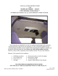
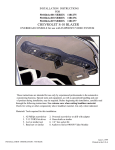
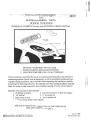
SO-O216A-xxx
SERIES
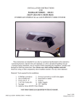
118127X
DODGEDURANGO
OVERHEAD
CONSOLE
for use with FLIPDOWN
VIDEO
SYSTEM
~
OPTIONAL ACCESSORIES MA y BE ADED:
1 ESCORT PASSPORT 4600 RADAR DETECTOR
2 MINI- TRIP COMPUTER FROM O.E.M. OVERHEAD
These instructions are intended for use only by experiencedprofessionals in the automotive
customizing business. Special tools and equipment, as well as specialized handling and care
of product during installation, may be required. Before beginning this installation, carefully
read through the following instructions. Use extreme care when cutting headliner material.
Check for wiring or other componentry above headliner material. Cut only where indicated.
Materials/
I.
3.
5;
Tools required for this installation:
#2 Phillips screwdriver
2. Powered screwdriver or drill with adapter
1/8" drill bit
4. ~" hex socket bit
Razor knife or similar
6. A wl or similar tool
7. Audiovox
Series 640/641 Video Module
,
FOR USE IN VEHICLES
EQUIPPED WITH FACTORY
REAR AIR CONDITIONING
INSTALLATION
I;,\,STRUCTION
# 44-0021A
INSTALLED
ONL Y.
Apr.13,1998
Printed in the U.S.A
[
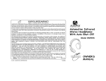
MA TERIALS
PROVIDED
FOR INST ALLA
TION
~
~
.
.
i
{
lrEMi~,pe~cription
..;!~",;;c..c;,
1
2
3
4
5
6
I
.
,gTY
..
SCREW, # 6 X Y2 PPH
13
SCREW,#8X*
6
HWH
SCREW, # 8 X 11/4 PWH
2
FRONT MOUNTING BRACKET
1
COMPUTER MOUNTING BRACKET
I
REAR MOUNTING BRACKET
I
7
8
9
RADAR DETECTOR HOUSING
I
BLOCK OFF
I
CONSOLE
I
10
FRONT LIGHT
I
11
FRONT LIGHT TRIM
I
~!
t
,~;.:~~':~,;;
" ,,-';;;c.:,;
1
~.
2
3
"
5
8
~
4
D
9
~
s
l
i
~
11
INSTALLATION
10
7
Apr. 13, 1998
Printed in the U.S.A.
INSTRUCTION # 44-0021A
2
c
;.
I!:
i.
..
~
({
~
$
"'
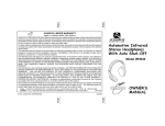
I. PREPARATION OF VEHICLE INTERIOR
.""4.'
~
*
;t
~
,;
,J:
if.
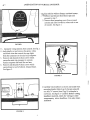
,;;::.:!~emoveand
discard fr.on(dOln~ light and
proceed to step 7.
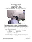
2. Remove front mounting screw from overhead
console and slide forward to release tabs at rear
,
of console. See figure 1.
I
0
/
/
FIGURE
1
.
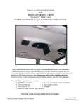
3. Disconnect wiring harness from console. See fig. 2
.
4. Individually cut and remove the green, white,
and black wires that control the map lights
,
from the connector on the mini-trip computer.
5. Remove and discard (4) four screws which
secure the mini-trip computer to console.
Retain computer and bezel for use later.
6. Remove and discard (4) four screws which
secure brace to roof of vehicle. Discard brace.
~
-
~
~
2
.
.
t
I
~
~
f
f
i
I
See figure 2.
-\:
FIGLTRE
v
2
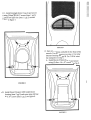
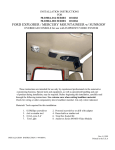
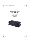
7. Carefully trim headliner as shown and install front
mounting bracket (item 4 pg 2). Secureusing (2)
two #8 x ~" screws (item 2 pg 2) in dimples in
roof brace. Seefigure 3. Caution: Before cutting
headliner material, check for wiring or other
componentry above headliner. Cut only where
indicated.
~
FIGURE
~
3
3
[
I
!
7"
T
~"
-~~:i"
~tC
~ ~5rf:;
.","
~",,~' ,~~
8. Carefully trim headliner and drill (2) two Y2"
holes in return air grille to allow for screws to
pass through when mounting bracket. See fig. 4.
FIGURE
4
T
1
t~
9. Install rear mounting bracket (item 6 pg 2) and
secure using (4) four # 8 x 3,{" screws (item 2
'--"-
pg 2). Make sure that holes in bracket align
with dimples in roof brace. See figure 5.
FIGURE
II. PREPARATION
5
OF CONSOLE FOR INSTALLATION
~
f
;:
L
~
10. Install the video system in console and secure
using hardware supplied with video system.
Start all screws before tightening. Be~n with
the rear center screw, then alternately tighten
screws around the perimeter of pod. Seefigure
6. Refer to owner's manual supplied with
video system. Caution: Do not overtighten
screws.
~.
,\
~
FIGURE
, I
6
4
.f
~
ii
W
~
i
t
';;
,.
i{
:'i
~;
bI;:
;,
".
:!
11.
Install
fro~,tjig4t(item
,-,,"= , "'"
10
-using (3) three::~~6;;kV2"
Install
light.
front light trim (item
See figure
pg
2)
and
screws {item
secure
i
1 pg'2)..
;}
~
II pg 2) around
7.
\
I
.
.
12. There are 3 options available for the front of the
console. For no accessorysee stepA. For radar
detector housing see step B. For O.E.M. minitrip computer see step C.
A. Install block off (item 8 pg 2) and secure
using (4) four # 6 x ,Y2"screws. Seefig. 8.
.,
FIGURE
8
B. Install Escort Passport 4600 radar detector
housing (item 7 pg 2) and secureusing (4) four
# 6x Y2"screws (item 1 pg 2). Seefigure 9.
FIGLRE
9
.;
if
~~
~
~
'I'
ii
"
~
ii
.if
9
c. Install O.E.M. mini-trip computer bezel from
the backside of opening in console.
Install computer mounting bracket (item 5 pg 2)
and secure using (2) two # 6 x Y2" screws (item
1 pg 2). See figure 10.
fj
ij
~
.
.n
FIGURE 10
Install O.E.M. mini-trip
computer and secure
using (4) four #6 x 1f2"screws (item I pg 2).
See figure 11. Do not overtighten screws.
FIGURE
6
11
f
~
:;:
...
III. INSTALLA TION OF CONSOLE
"
"" .
NOTE: Additional a"ssistance in mounting
'.~
the overhead console in vehicle is
advised to prevent damage to console or components.
c
~
~
rf
~J
;t
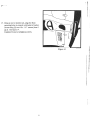
13. Install and route all accessory wiring, video
and audio cables, and any other added
component requirements to their respective
places in the vehicle. Refer to component
installation instructions for wiring diagrams.
The suggested routing of the video system
cable is as follows: Above the headliner from
~
r.
t
f
video system to B-pillar. Down the B-pillar
to the floor. Route the power lead to an
accessory controlled source. Connect the
ground lead to the vehicle chassis. Route the
remaining wiring (RCA plugs, Remote
Sensor extension, etc.) to the VCP location.
See figure 12. Connect per instructions
included with the video system. Ifvideo
system if to be used as a television, install an
appropriate antenna per instructions included
with the antenna.
14. Raise console into approximate position and
connect all wiring to components.Connect
wiring aI)d cabling to video system per
instructions included with \'ideo system.
15. Check function of all components and lights.
Seeoperating instructions for video system
operations check. For further assistance,refer
to the video system manual for the technical
support phone number listed for your area.
16. Carefully position console against headliner.
Releasevideo screenfrom locked position.
Lower video screento viewing position for
accessto mounting locations in top of video
system housing and align holes in housing
with holes in rear mounting bracket. Secure
using (4) four # 6 x Y2"screws (item 1 pg 2).
Seefigure 13.
Figure 13
Caution:
Do not overtighten
Figure 12
screws.
Use extra support for the console until secured to the
vehicle. Failure to do so may cause damage to console or installed components.
0;
ii
.
"'
"'
.r
#.
.
.
I.
~
~
j
~
~
'f
:f
~
o
:.:
~,
17. Using an awl or similar tool, align the front
mounting holes in console with holes in bracket.
Secure using (2) two # 8 x 1 ~" screws (item 3
pg 2). See figure 14.
Caution: Do not overtighten
screws.
Figure 14
.
}
.
.
,
il
);
8