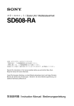
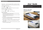
1
375 Marcus Boulevard • Hauppauge, NY 11788 • USA 631.273.0500 • Fax: 631.273.0771 e-mail: [email protected] Extensive Product Information Available at: www.ultraviolet.com Document No. 98 -1123E1 • Revised February 2007 • © 1994-2007 Atlantic Ultraviolet Corporation TABLE OF CONTENTS SAFETY WARNINGS.....................................................................................................................................................3 SAFETY INSTRUCTIONS ............................................................................................................................................3 PRODUCT APPLICATION ...........................................................................................................................................4 CONSTRUCTION ............................................................................................................................................................4 PRINCIPLE OF OPERATION .............................................................................................................................................4 LIMITATION OF USE ......................................................................................................................................................4 WATER QUALITY ..........................................................................................................................................................4 INSTALLATION .............................................................................................................................................................5 LOCATION.....................................................................................................................................................................5 DIMENSIONAL DATA .....................................................................................................................................................5 INSTALLATION...............................................................................................................................................................6 RECOMMENDED OPTIONS..............................................................................................................................................7 MAINTENANCE.............................................................................................................................................................8 INSPECTION ..................................................................................................................................................................8 LAMP-OUT PROTECTION ...............................................................................................................................................8 LAMP INSTALLATION OR REPLACEMENT .......................................................................................................................9 QUARTZ SLEEVE CLEANING OR REPLACEMENT ...........................................................................................................10 REPLACEMENT OF BROKEN QUARTZ SLEEVE ..............................................................................................................11 DISPOSAL OF MERCURY ADDED LAMP ........................................................................................................................11 OPTIONAL GUARDIAN ™ ULTRAVIOLET MONITOR SENSOR PROBE CLEANING.............................................................12 TROUBLESHOOTING ................................................................................................................................................13 TECHNICAL SPECIFICATIONS...............................................................................................................................14 OPTIONAL ACCESSORIES .......................................................................................................................................15 REPLACEMENT PARTS .......................................................................................................................................16-19 MightyPure™ MODELS MP13A, MP16A & MP22A .....................................................................................16-17 MightyPure™ MODELS MP36C, & MP49C ...................................................................................................18-19 USER ASSISTANCE .....................................................................................................................................................20 WARRANTY..................................................................................................................................................................20 PATENT NOTICE ...........................................................................................................................................................20 These instructions generally describe the installation, operation and maintenance of the MightyPure™ line of water purifiers, Models MP13A, MP16A, MP22A, MP36C and MP49C. Questions that are not specifically answered by these instructions should be directed to the Factory. Atlantic Ultraviolet Corporation takes all possible precautions when packaging equipment to prevent damage. Carefully inspect and report all damage upon receipt of product. Do not install damaged equipment. Follow all instructions on all labels and tags. Carefully inspect all packing materials before discarding to prevent the loss of accessories, mounting hardware, spare parts or instructions. 2 SAFETY WARNINGS • • All personnel should be alerted to the potential hazards indicated by the product safety labeling on this unit. The following conventions are used to indicate and classify precautions in this manual and on product safety labeling. Failure to observe precautions could result in injury to people or damage to property. ! This is the safety alert symbol. It is used to alert you to potential personal injury hazards. Obey all safety messages that follow this symbol to avoid possible injury or death. Danger indicates an IMMINENTLY hazardous situation, which, if not avoided, WILL result in death or serious injury. Warning indicates a POTENTIALLY hazardous situation, which, if not avoided, COULD result in death or serious injury. Caution indicates a POTENTIALLY hazardous situation, which, if not avoided, MAY result in minor or moderate injury. Caution used without the safety alert symbol indicates a potentially hazardous situation, which, if not avoided, may result in property damage. This symbol/pictorial is used to identify an ELECTRICAL SHOCK or ELECTROCUTION hazard. This symbol/pictorial is used to identify an ULTRAVIOLET LIGHT hazard. • Product safety labels should be periodically inspected and cleaned, as necessary, to maintain good legibility. Always replace illegible safety labels. Contact factory to obtain replacement safety labels. SAFETY INSTRUCTIONS ! WARNING: To guard against injury, basic safety precautions should be observed, including the following: 1. Read and follow ALL safety instructions. 2. Do not use this water purifier for other than its intended purpose as described in this manual. 3. Do not alter design or construction. 4. ! DANGER: To prevent the risk of severe or fatal electrical shock, special precautions must be taken since water is present near electrical equipment. Always disconnect power before performing any maintenance. 5. ! WARNING: Avoid exposure to direct or strongly reflected germicidal ultraviolet rays. Germicidal ultraviolet rays are harmful to the eyes and skin. 6. Intended for indoor use only. The water purifier should be protected from the elements and from temperatures below freezing. 7. Do not operate water purifier if power cord or plug is damaged. 8. Electrical power supplied, to the water purifier, MUST match power requirements listed on the water purifier. 9. Plug the water purifier into an approved ground fault circuit interrupt (GFCI) receptacle. 10. ! CAUTION: Do not operate without proper electrical ground. 11. Do not exceed water purifier’s maximum rated flow capacity. 12. Do not exceed maximum operating pressure of 100 PSI. 13. Read and follow all notices and warnings on the water purifier. 14. SAVE THESE INSTRUCTIONS. 3 PRODUCT APPLICATION CONSTRUCTION • • • • • • The water purifier is designed to mount horizontally. A drain port on the chamber aids in draining of the purifier. The water purifier chamber is passivated and electropolished type 316 Stainless Steel. The ballast housing is a combination of Stainless Steel Type 304 and Aluminum Alloy. Coated chambers are available for uses with special applications, consult Factory. Easy-off end caps allow for quick and easy lamp change, without disconnecting from the water supply or draining the purifier. No tools are required. PRINCIPLE OF OPERATION The MightyPure™ design has been carefully conceived to provide adequate germicidal dosage throughout the disinfection chamber. The dosage, as it applies to ultraviolet disinfection, is a function of time and the intensity of ultraviolet radiation to which the water is exposed. The exposure time, in seconds, is the total time it takes the water to flow through the disinfection chamber exposing it to the germicidal lamp. Exposure time is related to the flow rate; the higher the flow rate, the lower the exposure time or the lower the flow rate, the higher the exposure time. The ultraviolet intensity is the amount of energy, per unit time, emitted by the germicidal lamp. The Dosage is the product of ultraviolet intensity and the exposure time. The operation of the MightyPure™ is as follows: 1. Water enters the purifier and flows into the annular space between the quartz sleeve and the chamber wall. 2. Suspended microorganisms are exposed to the ultraviolet rays emitted by the germicidal lamp. 3. The translucent sight port, or optional ultraviolet monitor, provides visual indication of germicidal lamp operation. 4. Water leaving the purifier is instantly ready for use, no further contact time is required. LIMITATION OF USE The water purifier is intended for the use with visually clear water, not colored, cloudy or turbid. See “Water Quality” section below. The water purifier is NOT intended for the treatment of water that has an obvious contamination or intentional source, such as raw sewage; nor is the unit intended to convert wastewater to microbiologically safe drinking water. WATER QUALITY Water quality plays a major role in the transmission of germicidal ultraviolet rays. It is recommended that the water does not exceed the following maximum concentration levels: Table 1 - Maximum Concentration Levels Turbidity: Manganese: Total Suspended Solids: pH: Color: Hardness: Iron: 5 NTU 0.05mg/l 10 mg/l 6.5 - 9.5 None 6 GPG or 102.6 PPM 0.3 mg/l Effectively treating water with higher concentration levels than listed above can be accomplished, but may require added measures to improve water quality to treatable levels. If, for any reason, it is believed the ultraviolet transmission is not satisfactory, contact the factory. 4 INSTALLATION LOCATION 1. 2. 3. 4. 5. 6. 7. The water purifier is intended for indoor use only. The water purifier should be protected from the elements and from temperatures below freezing. The ambient temperature, in the area surrounding the water purifier, should be between 33 F and 100 F. Electrical power supplied to the water purifier MUST match power requirements listed on the water purifier. Use of a voltage surge protector is recommended. Plug water purifier into an approved ground fault circuit interrupt (GFCI) receptacle. The water purifier should be located in a dry, well-lit area, which provides enough room to perform routine maintenance. This includes a minimum distance of one chamber length from the chamber end, to allow for cleaning and/or the changing of the lamp and quartz sleeve as well as a minimum of 6" on the opposite end of the water purifier. The water purifier should always be located closest to the point of use. This reduces the chance of the purified water being re-contaminated by bacteria in the water distribution system after the water purifier. CAUTION: As with any water handling device, the water purifier should be located in an area where any possible condensation or leakage from the water purifier, any purifier accessory and/or plumbing will not result in damage to the area surrounding the water purifier. For added protection, it is recommended that a suitable drain pan be installed under the purifier. The drain pan must be plumbed to an adequate, free flowing, drain to prevent water damage in the event of a leak. There are numerous leak detection/flood stop devices, available on the market today, designed to stop the flow of water, reducing the chance of water damage due to leakage. For more details regarding leak prevention and/or limiting damages due to leaks, please contact the factory. The water purifier should be located after all other water devices, such as De-ionizers, Water Softeners, Carbon Filters, Pre-Filters, Reverse Osmosis, Pressure Tanks, and Pumps. This reduces the chance of the purified water being re-contaminated by bacteria in any of these units. DIMENSIONAL DATA Figure 1 - MightyPure™ Dimensional Drawing Table 2 - MightyPure™ Dimensional Data Model: MP13A A 6" B 13" C 5- 3/4" D 7" E 13- 1/2" F 3- 5/8" G 4- /16" H 8- 3/8" MP16A 8- 3/4" 16" 8- 3/4" 10" 16- 1/2" 3- 5/8" 4- 15/16" 8- 3/8" 3 3 14- /4" 22" 13- /4" 14- /2" 22- /2" 3- /8" 4- /16" 8- /8" MP36C 28- 1/2" 36" 16" 18" 36- 1/2" 4- 15/16" 5- 11/16" 9- 1/2" 1"m NPT 1 1- 1/2"m NPT 40- /8" 49" 26" 1 30" 1 1 49- /2" 5 15 4- /16" 15 /4"m NPT MP22A 7 1 Inlet/Outlet 1 /2"m NPT 3 MP49C 3 15 11 5- /16" 9- /2" /4"m NPT 5 INSTALLATION 1. Remove water purifier from shipping carton. Inspect water purifier, power cord and plug for damage. Do not operate if there is any damage to the purifier, power cord or plug. Models MP13A through MP22A are shipped with the lamps already installed, while the MP36C and MP49C lamps are packed separately. Keep the lamp aside for installation once the purifier has been properly installed. 2. Units occasionally experience damage in shipment due to the fragility of the quartz sleeve. It is therefore recommended to inspect the water purifier for damage to the quartz sleeve after it has been removed from the shipping carton. Each end of the unit as well as the inlet and outlet should be viewed to see if the quartz sleeve has experienced damage. If the quartz sleeve shows signs of damage it should be replaced before the purifier is pressurized. See “Quartz Sleeve Cleaning or Replacement” in the “Maintenance” section for the proper method of replacing the quartz sleeve in your water purifier. Figure 2 - Recommended Installation 3. The water purifier should be mounted horizontally on a flat dry surface. Secure the water purifier using the mounting holes in the ballast housing or with the optional wall mounting kit. The purifier should not be solely supported by its plumbing connections. 4. The water purifier must be connected to the cold water line only. 5. It is recommended that a 5-micron sediment filter be installed, in line, prior to the water purifier. The sediment filter will stop or trap any particulates from entering the water purifier. Particulates may cause damage to the quartz sleeve, as well as interfere with the purifier’s ability to disinfect the water. The sediment filter may also help to reduce the amount of routine cleaning of the quartz sleeve. 6. Shut off valves should be installed on both the inlet and outlet sides of the water purifier. The use of bypass valves is not recommended. The shut off valves allow the purifier to be isolated from the water supply, which is required when removing the quartz sleeve. 7. Unions should be installed on both the inlet and outlet of the water purifier; this will allow easy removal of the water purifier from the plumbing, if required. Apply Teflon® tape to threads of inlet and outlet ports to ensure a tight seal. 8. When all plumbing connections are complete, allow water to enter the water purifier at a low flow rate, until the purifier is pressurized. With the purifier pressurized, it should be checked for leaks. Once it is determined that there are no leaks, the inlet valve can be fully opened. 9. For Models with lamps packed separately, install lamp following the steps in “Lamp Installation or Replacement” section. ! CAUTION: Lamp and quartz sleeve are easily damaged. Exercise care when installing lamp. 10.Once the plumbing hook ups are made, it is a good practice to disinfect the “downstream” plumbing between the purifier and point of use. This is done by introducing chlorine into the purifier chamber, a 100-ppm solution of chlorine is suggested. With the chlorine in the purifier chamber, turn the ultraviolet purifier on. Open the “downstream” outlet until a chlorine odor is noticed. Close the outlet and allow the chlorine to remain in the plumbing for three (3) hours. Flush the plumbing with ultraviolet purified water; allow the water to run for several minutes before use. This will allow the chlorine to be flushed from the pipes. 6 RECOMMENDED OPTIONS 1 . Guardian™ Ultraviolet Monitor: Visually indicates the level of germicidal ultraviolet energy that penetrates the quartz sleeve and the water within the water purifier. The ultraviolet monitor is capable of operating an optional audio alarm and/or solenoid valve. The ultraviolet monitor will detect reduction of ultraviolet levels due to: • Fouling or deposits on the quartz sleeve. • Poor ultraviolet transmission through the water; color, turbidity, and organic or other impurities in the water can reduce or interfere with the transmission of ultraviolet rays. • Lamp outage, component or power failure. • Depreciation of the lamp output due to usage or other cause. Lamp output gradually depreciates with use. Lamp replacement is recommended once each year. • Use of the Guardian™ Ultraviolet Monitor is recommended by the U. S. Public Health Service “Criteria for the Acceptability of an Ultraviolet Disinfection Unit.” 2. Sentry™ Safety Sensor: Pilot lamps provide constant visual monitoring of normal operation. In the event of power or lamp failure the safety sensor indicates an alarm condition. The safety sensor is capable of operating an optional audio alarm and/or solenoid valve. 3. Steralert™: Lamp Status Alarm produces a high pitched, pulsed tone when the water purifier is no longer functioning due to lamp or power failure. 4. Flow Control Valve: Limits water flow to the rated capacity of the purifier. The flow control valve is located in line prior to the water purifier, and should be protected from ultraviolet exposure by the use of a 90-degree elbow fitting between the flow control valve and the water purifier. 5. Audio Alarm: Activated by the Ultraviolet Monitor or Safety Sensor, alerts the user to any malfunction detected. 6. Solenoid Valve: Operated in conjunction with the Ultraviolet Monitor, Safety Sensor or Time Delay Mechanism, this valve prevents water flow through the water purifier when an abnormal condition is detected or in the event of power failure. 7. Elapsed Time Indicator: A non-resettable display of the water purifier operating hours. Useful for scheduling and recording maintenance and lamp replacement. 8. Time Delay Mechanism: Provides a 2-minute warm up period during which the ultraviolet lamp achieves its full germicidal output before the water is allowed to flow through the water purifier. The time delay mechanism is used in conjunction with, and is electrically connected to the Solenoid Valve. 9. Wall Mount Kit: Stainless steel wall brackets provide quick and easy installation and professional finish. Pre-drilled and ready to install. Optimizes free air circulation to cool ballast housing. 10. Quantum Thermal Optimizer: Thermal relief valve used to help regulate the water temperature inside the water purifier's disinfection chamber. Since the relative ultraviolet output, of a germicidal lamp, is affected by temperature it is important to keep the lamp's temperature within the peak output temperature range. 7 MAINTENANCE The water purifier is designed to operate with a minimal amount of maintenance, providing the water quality does not exceed maximum concentration levels, see “Water Quality” in the “Product Application” section. Ordinary maintenance consists of; • Lamp replacement is recommended every 10,000 hours of operation, approximately 12 months of continuous service. • Cleaning of the quartz sleeve, when conditions warrant. • Always disconnect the water supply and completely drain the water purifier if it will be subjected to temperatures below freezing, for extended periods of time. INSPECTION 1. 2. Regularly inspect the water purifier to ensure that the germicidal lamp is still in operation. • On purifiers not equipped with the Ultraviolet Monitor, lamp operation can be verified by a visible glow through the translucent sight port. This provides an indication of lamp operation and does not indicate the level of ultraviolet intensity or transmission through the water. • On purifiers so equipped, the Guardian™ Ultraviolet Monitor provides visual indication of the ultraviolet intensity through the quartz sleeve and water in the purifier chamber. To ensure proper operation of the water purifier, regular biological testing should be performed on a schedule recommended by local public health authorities, or at minimum; at installation, quarterly for the first year of service and annually, at lamp replacement, for the life of the water purifier. LAMP-OUT PROTECTION On MightyPure™ MODELS MP16A, MP22A & MP36C If power is applied to the purifier without a lamp connected to the circuit or if the lamp fails, the purifier ballast's lamp-out protection will prevent the purifier from operating. If the ballast is plugged-in without a lamp or if the lamp fails, the ballast's lamp-out protection will prevent the ballast from operating. To reset: • Lamp replacement is recommended every 10,000 hours of operation, approximately 12 months of continuous service. • CONNECT lamp OR REPLACE failed lamp. • After 2 minutes, plug the ballast back into the outlet receptacle; it should resume proper operation. The ballast must remain unplugged for two (2) minutes to reset. 8 LAMP INSTALLATION OR REPLACEMENT Figure 3 - Lamp Replacement 1. 2. 3. 4. 5. 6. 7. Step 2 - Remove End-Cap Step 3 - Withdraw Lamp Step 4 & 5 - Remove Sockets Step 6 - Remove Lamp Disconnect power to water purifier. Remove both easy-off end caps by pulling each cap off static gland nut. Slide each end cap along the wire away from the socket. Carefully withdraw lamp approximately 2 inches from chamber while feeding lamp socket and lead wire on opposite end of chamber. While holding lamp end, carefully remove lamp socket on end now exposed. Next, carefully slide lamp back into chamber, until approximately 2 inches of the lamp is exposed on the opposite end. Hold lamp and remove lamp socket. Lamp should now be disconnected on both ends. Carefully remove lamp from chamber. Be sure to withdraw lamp straight out without angling until completely clear of quartz sleeve. ! CAUTION: Lamp and quartz sleeve are easily damaged. Exercise care when removing or replacing lamp. Reinstall lamp in reverse order. ! WARNING: Germicidal ultraviolet rays are harmful to eyes and skin. Do not restore power to water purifier until lamp and both easy-off end caps have been properly reinstalled. 9 QUARTZ SLEEVE CLEANING OR REPLACEMENT Figure 4 - Quartz Sleeve Cleaning or Replacement Step 4 - Remove Gland Nuts 1. 2. 3. Step 5 - Remove Washer & O-Ring Step 6 - Remove Quartz Sleeve Disconnect power to water purifier. Shut off water supply to water purifier via inlet and outlet shut off valves. Drain chamber by removing drain plug. Once the chamber is completely drained, remove any old sealing tape from the threads of the drain plug, rewrap with 1/2" wide Teflon® thread sealing tape, reinstall and tighten the drain plug. Follow the steps in “Lamp Installation or Replacement” to remove lamp. ! CAUTION: Lamp and quartz sleeve are easily damaged. Exercise care when removing or replacing lamp. 4. Unscrew static gland nuts from each end of the chamber. Avoid striking quartz sleeve with static gland nut. 5. Remove Teflon® washer and o-ring from both ends of quartz sleeve. Teflon® washer will sometimes remain with in the static gland nut. If so, remove Teflon® washer from static gland nut before proceeding. 6. Carefully remove quartz sleeve from chamber. NOTE: It is advisable to support the quartz sleeve on the opposite end with your finger so that it does not drop to the bottom of the chamber as it slides into the chamber. 7. Once the quartz sleeve is removed, clean with alcohol or a mild, non-abrasive detergent. Stubborn stains usually can be removed with a dilute hydrochloric acid. NOTE: Follow all manufacturer’s instructions and precautions when handling chemicals. 8. Reassemble in reverse order. Make sure the quartz sleeve protrudes an equal distance past each threaded nipple. Be sure o-rings are placed on quartz sleeve before Teflon® washer. 9. Tighten static gland nuts firmly by hand only, DO NOT USE HAND TOOLS. Tightening with hand tools is likely to cause quartz sleeve to break. 10. Slowly restore water supply to water purifier and check for leaks. 11. If no leaks occur, reinstall lamp, following the steps in “Lamp Installation or Replacement” section. 10 REPLACEMENT ! 1. 2. 3. 4. • • • 5. 6. 7. 8. 9. 10. 11. 12. 13. 14. 15. 16. OF BROKEN QUARTZ SLEEVE CAUTION: Broken Quartz is SHARP. It is recommended that protective goggles and gloves are worn when handling broken quartz sleeves. Disconnect power to water purifier. Shut off water supply to the water purifier via the inlet and outlet shut off valves. Drain the chamber by removing the drain plug. Once the chamber is drained, remove any old sealing tape from the threads of the drain plug, rewrap with 1/2" wide Teflon® thread sealing tape, reinstall and tighten the drain plug. Follow the steps in “Lamp Installation or Replacement” to remove lamp. To prevent damage to the electrical components, it is necessary to separate the ballast housing from the purifier chamber. On MightyPure™ Models MP13A, MP16A, and MP22A, the ballast housing is mounted to the purifier chamber using four (4) No. 8 x 3/8" long screws. Using a Phillips cross point screwdriver, carefully remove the four (4) screws, from along the sides of the ballast housing, and set aside. Separate the housing from the chamber. On MightyPure™ Models MP36C, and MP49C , the ballast housing is mounted to the purifier chamber using four (4) 1/4"-20 x 3/8" long hex head bolts. Using a 7/16" wrench or an adjustable wrench, carefully remove the four (4) bolts with the lock and flat washers, from along the top of the ballast housing, and set aside. Separate the housing from the chamber. Keep ballast housing and mounting hardware in a clean, dry area. Unscrew static gland nuts from each end of the chamber. Remove Teflon® washer and o-ring from both ends of quartz sleeve. Teflon® washer will some times remain within the static gland nut. If so, remove Teflon washer from static gland nut before proceeding. Carefully remove as much of the broken quartz sleeve as possible, from each end of the chamber. To remove fragments of quartz sleeve, hold the purifier vertically and shake. The quartz fragments will break and drop out of the purifier through the gland fitting. Flush water through chamber being careful to remove all quartz fragments from the interior of the chamber. Carefully discard all pieces of the broken quartz sleeve. Align the end of the replacement quartz sleeve with the gland fitting of the chamber. Carefully slide the quartz sleeve into the chamber, guiding it through the gland fitting. NOTE: Use care to keep the quartz sleeve parallel to the chamber. Angling the quartz sleeve in any direction could result in the breakage of the quartz sleeve. As the quartz sleeve nears the far end of the chamber, support the quartz sleeve by inserting your finger through the far end gland fitting and into the quartz sleeve. This will minimize the possibility of breaking the quartz sleeve as it passes through the gland fitting. Center the quartz sleeve in the chamber, making sure the quartz sleeve protrudes an equal distance past each threaded gland fitting, of the chamber. Re-install o-rings, Teflon® washers, and static gland nuts. Be sure o-rings are placed on quartz sleeve before Teflon® washer. Tighten static gland nuts firmly by hand only, DO NOT USE HAND TOOLS. Tightening with hand tools is likely to cause quartz sleeve to break. Re-assemble ballast housing to purifier chamber, using hardware removed in Step 4. NOTE: When re-assembling ballast housing to purifier chamber, electrical power cord should exit ballast housing from the end mounted opposite the drain plug. When all connections are complete, allow water to enter the water purifier at a low flow rate until the purifier is pressurized. With the purifier pressurized, it should be checked for leaks. See “Lamp Installation or Replacement” section to properly re-install the lamp into the water purifier. DISPOSAL OF MERCURY ADDED LAMPS Germicidal ultraviolet lamps, like standard fluorescent lamps contain small amounts of mercury. Mercury added lamps should not be placed in the trash. Dispose of properly. For further information regarding the disposal and recycling of lamps containing mercury, along with Federal and State requirements visit http://www.lamprecycle.org. Product Data Sheets for germicidal ultraviolet lamps can be found in the “PDF Library for Ster-L-RayTM germicidal Ultraviolet Lamps” section of http://www.ultraviolet.com. 11 OPTIONAL GUARDIAN™ ULTRAVIOLET MONITOR SENSOR PROBE CLEANING Figure 5 - Ultraviolet Monitor and Sensor Probe If after cleaning the quartz sleeve, there is no significant improvement in the ultraviolet intensity, as shown on the intensity meter, it may be necessary to clean the Ultraviolet Monitor's sensor probe. The sensor probe body mounts in a fitting, located in the center of the disinfection chamber, and protrudes into the chamber. 1. Disconnect power to the water purifier. 2. Shut off water supply to the water purifier via the inlet and outlet shut off valves. Drain the chamber by removing the drain plug. Once the chamber is drained, remove any old sealing tape from the threads of the drain plug, rewrap with 1/2" wide Teflon® thread sealing tape, reinstall and tighten the drain plug. 3. Disconnect power to the Ultraviolet Monitor; remove from chamber by loosening the two setscrews on the aluminum collar and lifting it free from probe body. 4. Unscrew the sensor probe and remove from the chamber. 5. Remove the quartz rod retainer cap, from the probe body. Take care not to damage the quartz rod, o-ring or the threads of the probe body. NOTE: It is recommended, when servicing the sensor probe, to work in a clean, dry area. 6. Once the quartz rod is removed, clean with alcohol or a mild detergent, and rinse with clean water. Stubborn stains usually can be removed with a dilute hydrochloric acid. NOTE: Follow all manufacturer's instructions and precautions when handling chemicals. Once the quartz rod has been cleaned, handle the rod by the sides, to avoid getting fingerprints on the quartz rod faces. 7. Clean the probe body, by removing any dirt or deposits on all surfaces. O-rings should be inspected and can be replaced if worn or damaged. 8. Reassemble, replacing the o-ring, quartz rod and securing in place with the quartz rod-retaining cap. Tighten the quartz rod-retaining cap by hand only, DO NOT USE HAND TOOLS. Tightening with hand tools my damage the quartz rod or o-ring seal. 9. Reinstall sensor probe into the center fitting of the chamber and tighten. 10. Slowly restore water supply to the water purifier, pressurize, and check for leaks. Once it is determined that there are no leaks, inlet valve can be fully opened. 11. Reposition Ultraviolet Monitor on probe body and tighten setscrews. 12. Restore power to the water purifier and ultraviolet monitor. If after the cleaning of the sensor quartz rod, there is still no significant improvement in the ultraviolet intensity, as shown on the intensity meter, proceed to the “Troubleshooting” section. 12 TROUBLESHOOTING ! CAUTION: Always disconnect power to the water purifier, before performing any service. IMPORTANT: This unit is to be serviced ONLY by qualified, and appropriately licensed, personnel. Table 3 - Troubleshooting Problem Purifier not operating. Possible Cause Corrective Action No electrical power… Verify that the purifier is connected to a live power source. Ballast Disconnect the purifier from utility power. Replace lamp. Lamp-out Protection The purifier must remain disconnected from power for (MP16A, MP22A & MP36C) two (2) minutes to reset. Cracked or broken quartz sleeve… Shut down purifier, drain, and replace quartz sleeve. See “Quartz Sleeve Cleaning or Replacement” in the “Maintenance” section. Quartz sleeve sealing o-ring (s) worn, damaged… Shut down purifier, drain, and remove static gland nut, replace sealing o-ring. See “Quartz Sleeve Cleaning or Replacement” in the “Maintenance” section. Poor, or loose, connections or fittings… Tighten suspect connection or fitting; or shut down purifier, drain, and remove fitting or connection. Clean threads; reapply thread sealing tape and reinstall. Quartz sleeve fouled… Clean quartz sleeve, see “Quartz Sleeve Cleaning or Replacement” in the “Maintenance” section. Sensor Probe, if equipped, lens fouled… Clean lens or Quartz Rod, see “Optional Ultraviolet Monitor Sensor Probe Cleaning” in the “Maintenance” section. Poor purifier performance AND/OR Low UV intensity Germicidal lamp output depreciating… Replace lamp, as it nears its end of life (EOL). See “Lamp Replacement” in the “Maintenance” section. (As indicated on Optional Guardian™ Germicidal lamp not functioning… Replace lamp. See “Lamp Replacement” in the “Maintenance” section. Ultraviolet Monitor). Low input voltage… Verify input voltage to purifier. Change in water quality… Have water tested to confirm that it does not exceed maximum recommended concentration levels for use with this purifier. Water leaking into/from purifier. 13 TECHNICAL SPECIFICATIONS Table 4 - Technical Specifications Model: MP13A MP16A MP22A MP36C MP49C Flow Rate (GPM): 2 3 6 12 20 Inlet\Outlet Size: 1 3 3 /4"m NPT 1"m NPT 1- 1/2"m NPT Number of Lamps: 1 1 1 1 1 Lamp Model No.: GPH212T5L GPH287T5L GPH436T5L G36T6L G48T6L Length: 13- 1/2" 16- 1/2" 22- 1/2" 36- 1/2" 49- 1/2" Width: 4- 5/16" 4- 5/16" 4- 5/16" 5- 11/16" 5- 11/16" Height: 8- 3/8" 8- 3/8" 8- 3/8" 9- 1/2" 9- 1/2" Chamber Diameter: 4- 1/4" 4- 1/4" 4- 1/4" 4- 1/4" 4- 1/4" Shipping Weight: 12 Lbs 12 Lbs 14 Lbs 22 Lbs 36 Lbs Voltage:c 120V 120V 120V 120V 120V Amps: .17A .23A .33A .65A .42A Frequency: 60Hz 60Hz 60Hz 60Hz 60Hz Power Consumption:d 14 Watts 18 Watts 24 Watts 44 Watts 54 Watts Lamp Watts: 10 Watts 14 Watts 20 Watts 39 Watts 50 Watts Max Operating Pressure: 100 PSI 100 PSI 100 PSI 100 PSI 100 PSI Ambient Temperature: 33° F - 100° F 33° F - 100° F 33° F - 100° F 33° F - 100° F 33° F - 100° F Quartz Sleeve: 1 1 1 1 1 Drain Plug: 1 1 1 1 1 Lamp Out Indicator: Translucent Sight Port Translucent Sight Port Translucent Sight Port Translucent Sight Port Translucent Sight Port Ultraviolet Monitor: Optional Optional Optional Optional Optional Audio Alarm: Optional Optional Optional Optional Optional Solenoid Valve: Optional Optional Optional Optional Optional Time Delay Mechanism: Optional Optional Optional Optional Optional Elapsed Time Indicator: Optional Optional Optional Optional Optional Quantum Thermal Optimizer: Optional Optional Optional Optional Optional /2"m NPT /4" NPT /4"m NPT /4" NPT /4" NPT /4" NPT /4" NPT c 220V 50Hz, 220V 60Hz, 12V, or 24V DC units are also available. Consult Factory for specific voltage requirements. d Total power consumption, including ballast loss. 14 OPTIONAL ACCESSORIES Optional accessories are available for operation at 120v 60Hz or 220v 50Hz, unless specified. Please specify. Consult Factory for 12v DC or other special input power requirements. Table 5 - Optional Accessories Optional Accessories Available for: Guardian™ Ultraviolet Monitor - Analog/Digital MP13A through MP49C Sentry™ Safety Sensor MP13A through MP49C Steralert™ MP13A through MP49C Audio Alarm MP13A through MP49C Elapsed Time Indicator Universal Input MP13A through MP49C Wall Mounting Kit MP13A through MP49C Time Delay Mechanism MP13A through MP49C Quantum Thermal Optimizer: MP13A through MP49C Solenoid Valve - Nylon (120v only) MP13A (1/2") through MP22A (3/4") c MP36C (1") c MP13A (1/2") through MP22A (3/4") Solenoid Valve - Brass MP36C (1") MP49C (1- 1/2") c MP49C (1- 1/2") MP13A (1/2") MP16A (3/4") Flow Control Valve d MP22A (3/4") MP36C (1") MP49C (1- 1/2") c Valve requires 10-PSI pressure drop for satisfactory operation. d Unless otherwise specified PVC flow control valves are supplied. All PVC and Stainless Steel flow control valves are male NPT. Consult Factory for other flow control valves. 15 REPLACEMENT PARTS MightyPure™ Models MP13A, MP16A & MP22A Figure 6 - Exploded View MP13A, MP16A & MP22A 16 Table 6 - Replacement Parts MP13A, MP16A & MP22A ITEM NO. DESCRIPTION QTY MP13A PART NO. QTY MP16A PART NO. MP22A QTY PART NO. 1 Easy-Off End Cap 2 25-1499A1 2 25-1499A1 2 25-1499A1 2 Rubber O-ring, Static Gland 2 00-1108B 2 00-1108B 2 00-1108B 3 Lamp Spacer 2 25-0208A 2 25-0208A 2 25-0208A 4 Lead Wire & Socket 2 05-1219B2 2 05-1219B2 2 05-1219B3 5 Lamp 1 05-1400 1 05-1098 1 05-1097 6 2 25-1492D 2 25-1492D 2 25-1492D 7 Static Gland Nut Teflon® Washer 2 25-1235A 2 25-1235A 2 25-1235A 8 Rubber O-ring, Quartz Sleeve 2 00-1238A 2 00-1238A 2 00-1238A 9 Quartz Sleeve 1 15-1110A 1 15-1111A 1 15-1112A 10 Sight Port Plug 1 30-1075 1 30-1075 1 30-1075 11 Drain Plug 1 27-1216 1 27-1216 1 27-1216 12 Speed Nut, 6-32 2 50-1314 - - - - 13A Ballast, 120v 60Hz 1 10-1070 1 10-1327 1 10-1036 13B Ballast, 220v 50Hz 1 10-1074 1 10-1327 1 10-1036 14 Screw, Mounting 2 50-0155 4 50-0155 4 50-0155 15 Ballast Housing 1 25-1104A 1 25-1105B 1 25-1544D 16 3 Screw, No. 8 x /8" long 4 50-1323 4 50-1323 4 50-1323 17 Chamber 1 25-1465E1 1 25-1465E2 1 25-1465E3 18A* Line Cord, (120v 60Hz) 1 35-1100 1 35-1100 1 35-1100 18B* Power Cord 6’ (220v 50Hz) 1 35-1452 1 35-1452 1 35-1452 Standoff, Mounting - - 2 50-0107 2 50-0107 19 * not depicted in drawing 17 REPLACEMENT PARTS MightyPure™ Models MP36C & MP49C Figure 7 - Exploded View MP36C & MP49C 18 Table 7 - Replacement Parts MP36C & MP49C ITEM NO. DESCRIPTION QTY MP36C PART NO. MP49C QTY PART NO. 1 Easy-Off End Cap 2 25-1499A1 2 25-1499A1 2 Rubber O-ring, Static Gland 2 00-1108B 2 00-1108B 3 Lamp Spacer - - 2 25-0209A 4 Lead Wire & Socket 2 05-1218A2 2 05-1218A2 5 Lamp 1 05-1343 1 05-1334 6 Static Gland Nut 2 25-1492D 2 25-1492D 7 Teflon® Washer 2 25-1235A 2 25-1235A 8 Rubber O-ring, Quartz Sleeve 2 00-1238A 2 00-1238A 9 Quartz Sleeve 1 15-1113A 1 15-1114A 10 Sight Port Plug 1 30-1075 1 30-1075 11 Chamber 1 25-1465G4 1 25-1465F5 12 Drain Plug 13 14 1 27-1216 1 27-1216 3 4 50-1034 4 50-1034 Lock Washer /4" 4 50-1321 4 50-1321 1 Screw, /4"-20 x /8" long 1 1 15 Flat Washer /4" 4 50-1317 4 50-1317 16 Ballast Housing Cover 1 25-0394A 1 25-0350A 17 3 Screw, No. 8 x /8" long 8 50-1323 8 50-1323 18 Speed Nut, 6-32 - - 2 50-1314 19A Ballast, 120v 60Hz 1 10-1036 1 10-1091 19B Ballast, 220v 50Hz 1 10-1036 1 10-0127 20 Ballast Housing 1 25-0395C 1 25-0351B 21 Screw, Mounting 4 50-0155 4 50-0376 22A* Line Cord (120v 60Hz) 1 35-1100 1 35-1100 22B* Power Cord 6’ (220v 50Hz) 1 35-1452 1 35-1452 Standoff, Mounting 2 50-0107 2 50-0375 23 * not depicted in drawing 19 USER ASSISTANCE Atlantic Ultraviolet Corporation makes every effort to ensure that the MightyPure™ Ultraviolet Water Purifiers are products of superior quality and workmanship. This manual describes the installation, operation and maintenance of the MightyPure™ Ultraviolet Water Purifiers. Please read and become familiar with the contents of this manual before installing or using this unit. If after reading the manual you still have questions, or concerns, regarding the installation or use of this unit, contact our offices, weekdays between 8:30 am and 5:00 pm Eastern time, at: Atlantic Ultraviolet Corporation 375 Marcus Boulevard Hauppauge, New York, 11788 Tel: 631.273.0500 Fax: 631.273.0771 E-mail: [email protected] Website: www.ultraviolet.com Please fill out and return the Owner Registration card immediately. If the card is missing from this manual, please contact any of our application specialists to obtain one. Atlantic Ultraviolet Corporation takes all possible precautions when packaging equipment to prevent damage. Carefully inspect and report all damage. Do not install damaged equipment. Follow all instructions on any labels or tags. Carefully inspect all packing materials before discarding to prevent the loss of accessories, mounting hardware, spare parts or instructions. For your convenience, record the following information below. The model and serial number can be found on a label located on the MightyPure™ Ultraviolet Water Purifiers. Keep this manual, along with proof of purchase, handy when contacting our offices. Purchased From: Date: Model: Serial No.: WARRANTY We warrant that this product will be free from defects in material and workmanship for a period of one year from the date of shipment thereof or the product’s total rated life, whichever first occurs. Within the warranty period we shall repair or replace such products, which are returned to us with shipping charges prepaid, and which are determined by us to be defective. This warranty will not apply to any product, which has been subjected to misuse, negligence, or accident; or misapplied; or modified; or repaired by unauthorized persons; or improperly installed. The Buyer shall inspect the product promptly after receipt and shall notify us at our main office in writing of claims, including claims of breach of warranty, within thirty (30) days after the Buyer discovers or should have discovered the facts upon which the claim is based. Failure of the Buyer to give written notice of a claim within the time period shall be deemed to be a waiver of such claim. The provisions of the above warranty are our sole obligation and exclude all other remedies or warranties, expressed or implied, including warranties of merchantability and fitness for a particular purpose, whether or not purposes or specifications are described herein. We further disclaim any responsibility whatsoever to the customer, or to any person, for injury to person, damage to, or loss of property or value caused by any product which has been subjected to misuse, negligence, accident; or modified or repaired by unauthorized persons; or improperly installed. Under no circumstances shall the Company be liable for any incidental, consequential or special damages, losses or expenses arising from the contract for this product, or in connection with the use of, or inability to use, our product for any purpose whatsoever. PATENT NOTICE No attempt has been made to determine the patent status of applications illustrated or described in this publication. Inclusion in this publication of any design or method of use, which may be patented, is not to be construed as promoting or sanctioning unauthorized use. 20