1
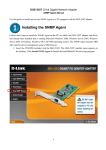
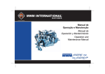
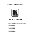
530T Window Automation System
The 530T window automation system controls the operation of two vehicle windows in both the up and down
directions. The 530T automatically rolls up the power windows when the security system is armed, as well as providing “one-touch” operation in either direction. The 530T can also be used to vent or roll the windows
completely down with an auxiliary channel from the security system.
Identifying Window Systems
Before wiring the 530T, it is important to understand how different window systems work. A 12VDC motor must
have (+)12V on one of its wires and (-) chassis ground on the other in order for it to operate. Most window
switches are connected directly to the window motor with two wires. These two wires will either rest at (-)
ground, (+)12V ignition, or sometimes they will rest open. In any of these systems, the switch, when activated,
will send (+)12V to one wire and (-) ground to the other wire. Which wire gets (+)12V and which wire gets (-)
ground determines which direction the motor will roll the window.
The three window systems will be referred to in this manual as type A, B, or C. To determine which type of system
you have, turn the ignition on, check the power window wires at the switch with a meter to see what polarity
they rest at. If they rest at (-) ground, you have a type A system. This is the most common system. If they rest
at 12V when the ignition is on, you have a type B system. This system is used on many European vehicles. If the
wires rest open, you have a type C system. The wiring for the type A and type C systems is exactly the same,
however, the type B system differs slightly.
NOTE: If the vehicle is equipped with any type of factory automatic full-travel or “one-touch”
system on the driver’s window, there may be a relay or module in the driver’s door. Be sure to interface with the wires between the module and the window motor.
© 2000 Directed Electronics, Inc.
1
N530T 1/00
Type A or Type C Windows
Type B power window systems are common in many European cars, such as Mercedes Benz and Porsche. In the
type B system, the power window wires will rest at (+)12V ignition and the switch will switch one of the wires
to (-) ground to activate the window motor. The wire that switches to (-) ground determines which direction the
window will move. Since the 530T monitors the state of the switch wires, the switch input polarity must be set
to the (-) negative setting (see dip-switch settings). Also when testing, the UP wire is the wire that remains at
(+)12V ignition while the window is moving up; the DOWN wire is the wire that remains at (+)12V ignition while
the window is moving down. This can be confusing because the 530T switch input wires are not going to be connected to the same wires as the motor output wires. Just remember, with the 530T installed, the switches are
no longer connected to the motors. They trigger the 530T to move the power windows one direction or the other.
NOTE: When wiring the 530T in a vehicle with a type B system, it is necessary to run the wires into
each door to be controlled by the 530T. If not, the master (driver’s door) switch will work, but the
switches in the other doors will not.
© 2000 Directed Electronics, Inc.
2
N530T 1/00
Type B Windows
Some window systems use either a central control module, or control modules in each door. These systems are
less common than direct wired systems. These can be found in many newer Volkswagens, BMWs, Isuzus, Maximas
and Grand Cherokees. If the vehicle has one of these systems, the 530T must be interfaced between the module(s)
and the window motor(s). This often requires the wires to be run into each door. The 530T monitors the AC
“noise” generated by the motion of the motor. For this reason the 530T cannot drive relays or control modules
in the system.
© 2000 Directed Electronics, Inc.
3
N530T 1/00
Systems With Factory Control Modules
Heavy Gauge Harness (H1) Wire Connection Guide
H1/1
H1/2
H1/3
H1/4
H1/5
H1/6
H1/7
H1/8
______
______
______
______
______
______
______
______
VIOLET
DRIVER-SIDE GROUND PATH INPUT
GREEN
DRIVER-SIDE DOWN MOTOR OUTPUT
BLUE
DRIVER-SIDE UP MOTOR OUTPUT
RED
(+)12V CONSTANT, 20A FUSED
BLACK
(-) CHASSIS GROUND
VIOLET/BLACK
PASSENGER-SIDE GROUND PATH INPUT
GREEN/BLACK
PASSENGER-SIDE DOWN MOTOR OUTPUT
BLUE/BLACK
PASSENGER-SIDE UP MOTOR OUTPUT
H1/1 VIOLET Driver-Side Ground Path Input: This wire provides the ground path for the driver-side motor.
Connect this wire to a paint-free surface on the vehicle chassis. Use a factory bolt if possible.
H1/2 GREEN Driver-Side Down Motor Output: Cut the driver-side down wire at the switch (see NOTE on page 1)
and connect this wire to the motor side of the down wire.
© 2000 Directed Electronics, Inc.
4
N530T 1/00
H1/3 BLUE Driver-Side Up Motor Input: Cut the driver-side up wire at the switch (see NOTE on page 1) and
connect this wire to the motor side of the up wire.
H1/4 RED (+)12V Constant, 20A Fused: Connect to a fused source of constant 12V. Make sure to connect this
wire to a 12V source capable of handling high current draw, such as the ignition harness or the battery.
H1/5 BLACK (-) Chassis Ground: Connect this wire to a paint-free surface on the vehicle chassis. Use a factory
bolt if possible.
IMPORTANT! Do not ground the 530T to the vehicle door. The 530T requires a solid ground to function properly, and the door hinges do not provide sufficient ground to the vehicle’s chassis.
H1/6 VIOLET/BLACK Passenger-Side Ground Path Input: This wire provides the ground path for the passengerside motor. Connect this wire to a paint-free surface on the vehicle chassis. Use a factory bolt if possible.
H1/7 GREEN/BLACK Passenger-Side Down Motor Output: Cut the passenger-side down wire at the switch (see
NOTE on page 1) and connect this wire to the motor side of the down wire.
H1/8 BLUE/BLACK Passenger-Side Up Motor Output: Cut the passenger-side up wire at the switch (see NOTE
on page 1) and connect this wire to the motor side of the up wire.
Light Gauge Harness (H2) Wire Connection Guide
H2/1
H2/2
H2/3
H2/4
H2/5
______
______
______
______
______
BROWN
DRIVER-SIDE UP SWITCH INPUT
WHITE
DRIVER-SIDE DOWN SWITCH INPUT
RED/WHITE
(-) AUXILIARY INPUT
ORANGE
(-) GROUND WHEN ARMED
GRAY
H2/6 ______
BROWN/BLACK
H2/7 ______
WHITE/BLACK
(-) OUTPUT DURING ACTIVATION
PASSENGER-SIDE UP SWITCH INPUT
PASSENGER-SIDE DOWN SWITCH INPUT
H2/1 BROWN Driver-Side Up Switch Input: Connect this wire to the driver-side switch of the up wire.
H2/2 WHITE Driver-Side Down Switch Input: Connect this wire to the driver-side switch of the down wire.
H2/3 RED/WHITE (-) Auxiliary Input: Connect this wire to a (-) validity channel output of the security system.
H2/4 ORANGE (-) Ground-When-Armed: Connect this wire to the (-) ground-when-armed output of the
security system. This wire can also be connected to an auxiliary channel of the security system to roll the
windows up.
© 2000 Directed Electronics, Inc.
5
N530T 1/00
NOTE: If the security system does not have a ground-when-armed output, a negative lock pulse
from the security system can be used to roll the windows up, as shown in the following diagram.
H2/5 GRAY (-) Output During Activation: Connect this wire to an optional relay (P/N 610T) to bypass sensors
which may trigger the security system during operation. This wire continues to output negative (-) ground for 5
seconds after the window motors have stopped.
H2/6 BROWN/BLACK Passenger-Side Up Switch Input: Connect this wire to the passenger-side switch (see
NOTE on page 1) of the up wire.
H2/7 WHITE/BLACK Passenger-Side Down Switch Input: Connect this wire to the passenger-side switch (see NOTE
on page 1) of the down wire.
Dip Switch Settings
The 530T uses internal resistors to change the amount of force required to drive the window motors. These resistors are controlled by a group of dipswitches on the side of the module. Some vehicles use very efficient motors
and little force is needed. This would require the switches to be set to a low setting. Some newer imports, such
as Honda Accords and Civics, may require a lower setting. Others use very inefficient motors, or the windows seem
“harder” to roll up. Some examples would be older domestic cars, as well as many full-size pickups. These vehicles require the switches to be set to a higher setting.
Switches 1- 4
© 2000 Directed Electronics, Inc.
6
N530T 1/00
Switch 5
Switch Input Polarity
ON (-) OFF (+)
Dipswitch #5 controls the polarity that the 530T switch input wires will respond to. For type A and type C
systems, it must be set to the OFF (+) position. When the switch is in the off position the 530T responds to (+)
positive inputs on its switch wires. If your vehicle has a type B system, this switch must be set to the ON (-)
position, so the 530T will respond to (-) negative inputs on its switch wires. Remember, the type B system
switches its wires to (-) ground rather than (+)12V.
Mounting the Control Module
When mounting the control module, always locate it as close to the window motor as possible. The driver-side kick
panel is an ideal location. If “one-touch” operation from the passenger-side switch is desired, interface with the
passenger-side wires between the passenger-side switch and the motor. This usually requires the passenger-side wires
to be extended and run into the passenger-side door. When extending the wires, use no smaller than 14 gauge wire.
IMPORTANT! Do not mount the control module in the vehicle door, as water damage will result. The
best results are obtained by mounting the control module inside the vehicle, as close to the window
motor as possible, in one of the kick panels.
Operating Instructions
To roll the windows up:
Simply arm the vehicle security system. The windows will roll up completely.
To arm the security system and leave the windows down:
1. Press the auxiliary channel.
2. Within 5 seconds arm the security system.
3. The security system will arm, but the windows will remain down.
To vent the windows:
At any time, press and release the auxiliary channel. The windows will vent about two inches.
To roll the windows down:
At any time, press and hold the auxiliary channel for three seconds. The windows will roll all the way down.
To activate “one-touch” operation:
1. Turn on the ignition.
2. Tap the power window switch in either direction. The window will open or close completely.
To stop the window:
1. Turn on the ignition.
2. Tap the power window switch in either direction while the window is in motion.
© 2000 Directed Electronics, Inc.
7
N530T 1/00
NOTE: If “one-touch” operation is desired from the passenger-side switch, the passenger-side wires
must be run into the passenger-side door and interfaced between the passenger-side switch and the
motor.
NOTE: If using a delayed auxiliary channel from the security system, such as channel 2, to control
windows down operation, the transmitter button will need to be pressed for 1.5 seconds to vent
the windows or 4.5 seconds to roll the windows all the way down.
Troubleshooting
The windows do not move, and the 530T fuse blows.
The switch side and the motor side connections may be reversed. Always make these determinations while using
the master switch (if there is one), and cut both wires before testing if any uncertainty exists.
The window moves an inch or so, and stops.
Does that window have a one-touch module? If so, make sure the wires are correctly interfaced at the motor and
not at the switch.
Is the window too efficient, or inefficient? If you help the window up does it move the entire direction? If so,
the dipswitches must be set to a higher setting. If you apply pressure to the outside of the glass, does the
window move the entire direction? If so, the dipswitches must be set to a lower setting.
One window works fine, but the other doesn’t move.
Does the window in question have a one-touch module? If so, make sure the wire connections were made between
the module and the window motor.
Try increasing or decreasing the resistance for that one window only (see Dipswitch Settings section of this
guide). If that has no effect, try reversing the passenger- and driver-side wires. Has the problem now switched
to the opposite window? If so, check the 530T. If not, double-check the switch side and motor side wire to be
sure they are not reversed.
How can I control a sunroof?
We recommend using a 529T instead of a 530T.
I can’t find any wires on the switch that seem to work.
Some new vehicles use unusual window control modules. Many of these require the 530T wires to be run into
each door. Some examples are listed below. If you are unsure, call DEI for details. The Nissan Maxima, Pathfinder,
Volkswagen Corrado, Passat, Golf, Jetta, Honda Passport/Isuzu Rodeo and most BMWs are examples of vehicles
with window control modules.
© 2000 Directed Electronics, Inc.
8
N530T 1/00