1
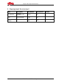
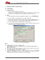
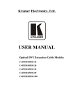
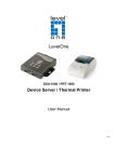
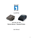
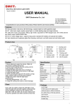
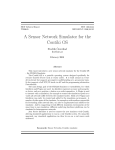
MCU-AN-510048-E-10
32-BIT MICROCONTROLLER
MB9B610 Series
ETHERNET_FLASH_LOADER
USER MANUAL
TM
ARM and Cortex-M3 are the trademarks of ARM Limited in the EU and other countries.
Revision History
Revision History
Version
Date
Updated by
1.0.0
2012-11-1
FSS
Approved by
Modifications
Initial version
Specifications are subject to change without notice. For further information please contact each office.
All Rights Reserved.
The contents of this document are subject to change without notice.
Customers are advised to consult with sales representatives before ordering.
The information, such as descriptions of function and application circuit examples, in this document are presented solely
for the purpose of reference to show examples of operations and uses of FUJITSU SEMICONDUCTOR device; FUJITSU
SEMICONDUCTOR does not warrant proper operation of the device with respect to use based on such information. When
you develop equipment incorporating the device based on such information, you must assume any responsibility arising
out of such use of the information.
FUJITSU SEMICONDUCTOR assumes no liability for any damages whatsoever arising out of the use of the information.
Any information in this document, including descriptions of function and schematic diagrams, shall not be construed as
license of the use or exercise of any intellectual property right, such as patent right or copyright, or any other right of
FUJITSU SEMICONDUCTOR or any third party or does FUJITSU SEMICONDUCTOR warrant non-infringement of
any third-party's intellectual property right or other right by using such information. FUJITSU SEMICONDUCTOR
assumes no liability for any infringement of the intellectual property rights or other rights of third parties which would
result from the use of information contained herein.
The products described in this document are designed, developed and manufactured as contemplated for general use,
including without limitation, ordinary industrial use, general office use, personal use, and household use, but are not
designed, developed and manufactured as contemplated (1) for use accompanying fatal risks or dangers that, unless
extremely high safety is secured, could have a serious effect to the public, and could lead directly to death, personal injury,
severe physical damage or other loss (i.e., nuclear reaction control in nuclear facility, aircraft flight control, air traffic
control, mass transport control, medical life support system, missile launch control in weapon system), or (2) for use
requiring extremely high reliability (i.e., submersible repeater and artificial satellite).
Please note that FUJITSU SEMICONDUCTOR will not be liable against you and/or any third party for any claims or
damages arising in connection with above-mentioned uses of the products.
Any semiconductor devices have an inherent chance of failure. You must protect against injury, damage or loss from such
failures by incorporating safety design measures into your facility and equipment such as redundancy, fire protection, and
prevention of over-current levels and other abnormal operating conditions.
Exportation/release of any products described in this document may require necessary procedures in accordance with the
regulations of the Foreign Exchange and Foreign Trade Control Law of Japan and/or US export control laws.
The company names and brand names herein are the trademarks or registered trademarks of their respective owners.
Copyright © 2011 Fujitsu Semiconductor Limited Asia All rights reserved.
MCU-AN-5100XX-E-10 – Page 2
Contents
Contents
REVISION HISTORY ............................................................................................................ 2
CONTENTS .......................................................................................................................... 3
1 INTRODUCTION .............................................................................................................. 4
1.1
Purpose ................................................................................................................... 4
1.2
Definitions, Acronyms and Abbreviations ................................................................ 4
1.3
Reference Documents ............................................................................................. 4
2 DEVELOPMENT ENVIRONMENT ................................................................................... 5
3 ETHERNET FLASH LOADER OVERVIEW ..................................................................... 6
4 ETHERNET FLASH LOADER DEMO .............................................................................. 7
4.1
Demo Steps ............................................................................................................ 7
4.2
Demo features ......................................................................................................... 8
4.3
Memory Allocation ................................................................................................... 9
4.4
Limitations ............................................................................................................. 10
5 ADDITIONAL INFORMATION ....................................................................................... 11
MCU-AN-5100XX-E-10 – Page 3
Chapter 1 Introduction
1 Introduction
1.1
Purpose
This document describes the Ethernet flash loader of MB9BF618T/S, as well as presents a
demonstration package based on a free TCP/IP stack, lwIP (lightweight IP).
The Ethernet flash loader is one of implementations for In-Application Programming (IAP),
which means upgrading firmware in the field using the MCU communication peripherals
(such as UART, USB, Ethernet, etc...). Customers can perform the firmware update without
teardown of the product.
Ethernet is often the preferred method for implementing IAP for reasons below,
High speed (10/100 Mbps)
Long distance through network
Construct on widely used protocols (FTP, TFTP, HTTP)
1.2
Definitions, Acronyms and Abbreviations
API
Application Programming Interface
I/F
Interface
IAP
In-Application Programming
EVB
Evaluation board
MAC
Media Access Controller
PHY
Physical Layer
lwIP
Lightweight IP
FTP
File Transfer Protocol
TFTP
Trivial File Transfer Protocol
HTTP
Hypertext Transfer Protocol
1.3
Reference Documents
[1].MB9Bxxx-MN706-00002-4v0-E.pdf
[2].MB9BF616S-DS706-00014-0v01-E.pdf
[3].MB9BF210T_610T-MN706-00015-1v0-E.pdf
[4].Design and Implementation of the LWIP TCP/IP Stack, Feb,2001, Adam Dunkels.
[5]. http://lwip.wikia.com/wiki/LwIP_Wiki
MCU-AN-5100XX-E-10 – Page 4
Chapter 2 Development Environment
2 Development Environment
Name
Description
Part Number
Manufacturer
IAR EWARM
Software
Developing IDE
V6.40
IAR
J-link
MCU Emulator
J-link
IAR
Hardware
platform
FSSDC-9B618FSS
EVB
MCU-AN-5100XX-E-10 – Page 5
Remark
Chapter 3 Ethernet Flash Loader Overview
3 Ethernet Flash Loader Overview
To demonstrate the Ethernet flash loader, two projects will be involved,
Flash loader project – Retrieve application image and flash it into internal flash, as well
as verification of its version and checksum before running it.
User application project– Demo project to produce application image, which will make
the LED (green) of the EVB blinking .
The protocol adopted for communication between PC and EVB is TFTP, which is widely
used in embedded applications to upgrade firmware.
TFTP is a simple file transfer protocol working on top of the UDP layer and it is mainly used
in a LAN. Based on client/server mode, the client will request a file transfer (read or write
operation) from a server.
In the Ethernet flash loader, a free tool Tftpd32 (http://tftpd32.jounin.net ) running on the PC
will act as TFTP client while the EVB will be the TFTP server.
During firmware updating (as shown in figure1), the client will transfer a bin file on the PC to
EVB, which will flash it into the dedicated internal flash. And only write request is supported
by the EVB to simplify the design.
Figure 1 IAP over Ethernet
MCU-AN-5100XX-E-10 – Page 6
Chapter 4 Ethernet Flash Loader demo
4 Ethernet Flash Loader demo
4.1
a.
b.
Demo Steps
Hardware Setting
Burn the flash loader image into the EVB.
Compile the user application project to produce the application bin image (Using
tool to convert the image file from Hex or MHX to bin file when necessary)
Steps
1)
Open Tftpd32 tool and select the application image bin file (e.g. D:\FM3\LED.bin)
2)
Set the IP address, port and block size as shown in figure 2 *.
3)
Power on board (burned with flash loader image) and press down button on the
joystick within 10 seconds. The LED will be turned on before button is pressed.
4)
Press the “Put” button on the Tftpd32 tool to start the update.
5)
The LED will be blinking when the update succeeds and MCU jumps from flash
loader program to run the application program.
Figure 2 TFTP client tool configuration
*Note:
IP address comes from static setting by default.
DHCP_DEMO micro definition in board.h needs to be enabled to support getting IP
address through DHCP.
The Tftpd32 tool should be configured as shown in figure 3 before retrieving the IP
address (e.g. 192.168.1.20) and setting it in figure 2.
If the DHCP_DEMO micro definition is enabled while DHCP server is not configured
properly or not available, the EVB will fail to retrieve the IP address per DHCP.
Thereafter a default IP address of 192.168.1.25 will be adopted.
MCU-AN-5100XX-E-10 – Page 7
Chapter 4 Ethernet Flash Loader demo
Figure 3 DHCP server configuration and retrieve the IP address
The LED will indicate the status of the flash loader operation.
Table1 LED status
4.2
LED (Green)
On
Off
signification
Boot project is running and Flash loader User application
waiting for selection of flash program
is is running.
loader program.
running.
Demo features
LwIP functionality of UDP
Ethernet driver of MCU
Flash operation of MCU
The H/W resource used in this solution includes:
1) Ethernet MAC0 of the MCU
2) System timer
3) Dual Timer: Used for LED blinking control
4) Flash I/F: The I/F to operate the MCU internal Flash ROM
5) NVIC: The interrupt related resource
6) Clock: The clock for the whole system
Figure 4 is the flow chart of this demo.
MCU-AN-5100XX-E-10 – Page 8
Blinking
Chapter 4 Ethernet Flash Loader demo
When power on, if the “down” button is pressed within specified time (such as 10seconds),
the Ethernet flash loader will run, which will communicate with the TFTP client to retrieve
image data and jump to execute the valid user code.
Start
SysInit
Flash loader is selected ?
Y
Get IP address
Update user
code
N
Jump to run
user code
Y
End
Checksum and version
verified
N
Figure 4 Flow chart
4.3
Memory Allocation
Figure 5 Memory map of M9BF618 flash memory
MCU-AN-5100XX-E-10 – Page 9
Chapter 4 Ethernet Flash Loader demo
Internal RAM
Sector of flash
loader
SA4~SA7
(32K)
Internal ROM
Sectors of Demo
User Code SA10
SA11 (128K)
Figure 6 Code allocation
The Ethernet loader code of MCU will be allocated at the SA4~SA7.
The user application program will be allocated at SA10 and SA11, whose vector table shall
be placed at the beginning of the sector, as shown in figure 7.
0x20000~0x200FF
Vector Table ( 256B)
0x20100~0x2010F
(14B reserved)
Version Flag ( 2 B)
0x20110~0x3FFFF
User Code (<128KB)
Figure 7 User code components
Note:
While the Ethernet flash loader operates the internal flash, the related flash R/W API will be
copied and run in internal RAM area.
4.4
Limitations
In the design of this flash loader, the following limitations are treated as design assumptions.
Supporting write request command only for TFTP.
The Ethernet flash loader will target to work on LAN only (the client and EVB are
connected to the same switch of the network).More complex network topology will be
supported in the further enhancement.
MCU-AN-5100XX-E-10 – Page 10
Chapter 5 Additional Information
5 Additional Information
For more Information on FUJITSU semiconductor products, visit the following websites:
English version address:
http://www.fujitsu.com/cn/fsp/mcu/32bit/fm3/an.html
Chinese version address:
http://www.fujitsu.com/cn/fss/mcu/32bit/fm3/an.html
MCU-AN-5100XX-E-10 – Page 11