1
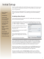
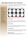
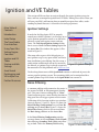
TunerStudio MS
New User Guide
Preface
This New User Guide for TunerStudio MS is designed to help the DIY mechanic
who recently completed a MegaSquirt conversion gain basic skills and improve their
interaction with the TunerStudio software.
This guide does not address tuning procedure, tuning theory, or profess, attempt, or
advise in any way the act of tuning a vehicle, engine, or motor. That information is
extensively documented by numerous sources including the MS EFI forum, MSExtra.com, and innumerable other sources both online and in print.
This guide was developed in cooperation with Phil Tobin, author of the TunerStudio
software to make the transition from the carburreted world to modern electronic
fuel injection easier.
The author of this guide can not and will not take any responsibility for damages
caused to persons or property as a result of techniques described in this manual.
DO NOT attempt to use the software while in a moving car.
DO NOT tune your vehicle on public roads
DO stop the car to make adjustments to your tune.
DO schedule time on a dyno, drag strip, or private road or track for tuning
This guide is provided free of charge. If asked to pay for this publication, please contact EFI Analytics directly.
i
Table of Contents
Introduction
System Requirements
1
Initial Setup
Creating a New Project
2
The TunerStudio User Interface
4
Using Tune Files
5
Setting Engine Constants
Calibrating Engine Sensors
6
Associating a Tune File With a Project
Coolant Temperature Sensor
Manifold Air Temperature Sensor
Throttle Position Sensor
MAP Sensor
AFR Table (EGO Sensor)
Trigger Wheel Settings
Fuel Constants
Required Fuel
1
2
5
6
6
7
7
8
8
9
10
10
Ignition and VE Tables
11
Startup and Idle Settings
Cranking Settings
14
Accel Enrich
16
Datalogging and VE Analyze Live
17
Further Resources
19
Ignition Settings
Noise Filtering
VE and Ignition Table Manipulation
Table Controls
Priming and Cranking Pulse
Afterstart Enrichment
Idle Air Control
Extended and Advanced Tabs
Datalogging
VE Analyze Live
Heat Maps
11
11
12
13
14
14
15
15
16
17
17
18
ii
Introduction to TunerStudio MS
Welcome to TunerStudio MS, the most popular and capable MegaSquirt tuning
solution available today. TunerStudio is the most widely used tuning software for the
MegaSquirt family of controllers, and is available either as a free download with essential features, or for purchase with expanded features and capabilities.
Main Table of
Contents
Introduction
Initial Setup
The TunerStudio
User Interface
Using Tune Files
Setting Engine
Constants
Ignition and VE
Tables
Startup and Idle
Settings
Accel Enrich
Datalogging and
VE Analyze Live
Further Resources
This guide will cover the paid version of the software, and will familiarize new users
with the basic functions of the software program. A basic understanding of the TunerStudio software is a crucial aspect of a successful tuning process.
System Requirements
TunerStudio is designed to be a lightweight application, and will run on many
computers with minimal resources without issue. It is suggested that a cheap
used laptop be purchased for tuning purposes to prevent damage to a more
expensive machine in a garage and vehicular environment.
Below you will find a list of suggested system requirements for the laptop running
TunerStudio MS. The software can be run on almost any computer, but computers
with better video card capabilities will be able to render gauges quicker and more
smoothly.
•Windows 98 or above
•Apple OSX, Leopard or above
•Linux (Most distros)
•Java Runtime Environment 1.7
•1GHZ Processor
•512mb RAM
DB9 Serial Port or USB to Serial Port Adapter
TunerStudio has been successfully installed and run on computers with processors
as slow as 366MHZ, and with a few adjustments, can be made to run smoothly on
computers that do not meet the suggested system requirements. TunerStudio can be
optimized for slower machines in the following ways:
•Dashboard Anti Aliasing - Right Click on the dashboard and choose the option for
Antialiasing. This being on has little to no impact with good video drivers, however on
older machines, antialiasing being on can double CPU usage.
•Dashboard selection - The default dash with the 8 gauges has no gauges overlapping whereas other layouts do overlap gauges. On slower computers, keep the default
dashboard.
•Modal Dialogs - Under the Menu Options-->Performance-->Modal Dialogs , this
options will stop animating the dashboard gauges while any dialogs are open so your
CPU can focus on the dialog at hand. Any data logging continues.
1
Initial Setup
After successfully installing TunerStudio MS on your computer, the first step is to set
up the program to communicate with your ECU. TunerStudio uses a feature called
Project Setup to do this.
Main Table of
Contents
Introduction
Initial Setup
Please verify that your MegaSquirt ECU is properly wired, and turns on when the
vehicle is powered on. If the ECU is wired correctly, proceed with the following
steps.
Creating a New Project
The TunerStudio
User Interface
Attach one end of the DB9 serial cable to the ECU, and the other to the tuning computer with TunerStudio installed.
Using Tune Files
1: Open TunerStudio. If this is the first time TunerStudio has been run, the Create
New Project dialog box (Figure 1.1) will appear automatically. If it does not, simply
go to File -> Project -> New Project.
Setting Engine
Constants
Ignition and VE
Tables
Startup and Idle
Settings
Accel Enrich
Datalogging and
VE Analyze Live
Further Resources
2: Create a name for the project, then turn
the key of the vehicle on to power on the
MegaSquirt ECU.
3: Click the Detect option beside the ECU
Definition heading.
4: Once TunerStudio has detected the appropriate ECU configuration, turn the key
off.
5: Enter a brief project description.
Figure 1.1: New Project Dialog Box
Once the above steps have been completed, we can proceed with configuring the
project. Click Next in the Create New Project dialog box. The next screen that appears will be a series of Configuration Settings (Figure 1.2), settings that will influence how the MegaSquirt ECU interprets the data it receives from some engine
sensors, and how TunerStudio displays some of the information it receives.
When this screen appears, the first pull-down menu is for EGO O2 Sensor choice.
TunerStudio provides for several options for popular wideband and narrowband
oxygen sensors. Choose the option appropriate for your application.
The next menu offers a choice of Lambda Display methods, between AFR and
Lambda. For most beginning users, AFR will be the more useful, and is far more
commonly used. If AFR is chosen, the value will be shown as a ratio of Parts Oxygen
2
to Parts Fuel (e.g. 14.7:1, or stoichemetric). If the Lambda option is chosen, TunerStudio will display a voltage reading instead of the ratio reading of AFR.
Temperature Choice is simply the option to choose between Celsius or Fahrenheit
temperature display.
Main Table of
Contents
Introduction
Initial Setup
The TunerStudio
User Interface
Using Tune Files
Setting Engine
Constants
Ignition and VE
Tables
Startup and Idle
Settings
Accel Enrich
Datalogging and
VE Analyze Live
Further Resources
MAP/Baro Setup is the option to choose
between barometric correction for the
manifold absolute pressure reading, or
not. By default, this setting is MAP Baro
OFF, and unless your ECU has a dual map
sensor, it should remain off. If you ordered
your ECU with the Mapdaddy sensor, or
if you built the ECU yourself with the dual
MAP sensor option, you should choose
the MAP Baro ON setting. More settings
regarding this item will be discussed in the
Sensor Calibration section.
Figure 1.2: Configuration Settings
The next option is Additional Fuel. This setting is used to set up control of an additional fuel, in this case Nitrous Oxide. It is highly unlikely that you will need to
configure this setting at this point, so leave it set to the default N2O OFF setting. If
you decide to add nitrous at a later point, it can be reconfigured.
X_Tau_Visible is the last option in this dialog box. X-Tau refers to the quantity of
fuel (X) that clings to the intake tract walls for a given time (Tau) after a fuel injector
pulse. Leave this option Activated. TunerStudio will automatically calculate X-tau
and actively make corrections if needed.
At this point, we can proceed by clicking
Next. A third dialog box will open, prompting you to verify your project’s communications settings. They should be correct as a
result of clicking Detect on the first Create
New Project dialog box, but they can be
checked again by powering the ECU, and
clicking Test Port.
The final option in the project creation
process is choosing a layout for gauges on
TunerStudio’s Dashboard.
Figure 1.3: Default Dashboard
There are several options available with
varying levels of functionality, but for the purposes of this manual, it is advised that
you retain the Default dashboard layout shown in Figure 1.3. The dashboard gauge
layout is easily changed in the future if you prefer. If you purchased TunerStudio, it is
possible to create totally custom gauge clusters and dashboards.
3
The TunerStudio User Interface
In order to make future tuning easier, it is helpful to become acquainted with the
basic layout of TunerStudio. There are four basic areas on the screen: the Menu Bar,
Access Bar, Dashboard, and Notification Area (Figure 2.1)
Main Table of
Contents
Introduction
Initial Setup
The TunerStudio
User Interface
Using Tune Files
Setting Engine
Constants
Ignition and VE
Tables
Startup and Idle
Settings
Accel Enrich
Datalogging and
VE Analyze Live
Further Resources
Figure 2.1: TunerStudio User Interface
The Menu Bar
Similar to the menu bar present in most programs, the TunerStudio menu bar
contains options that influence the operation of the software program. Software
preferences, project setup, datalogging, sensor configuration, and more are accessed
through the Menu Bar.
The Access Bar
The Access Bar is where you will find most of the tuning tools that you will need.
The VE table, Ignition table, AFR table, Startup and Idle settings, Knock Sensor settings, and many, many more features are located here.
The Dashboard
The Dashboard is where all of the engine gauges are located. There are eight spots for
gauges in the default layout, and each gauge can be changed by right-clicking on the
gauge face and choosing a different one from the drop-down list.
Notification Area
This small area contains notifications of what functions the ECU is currently performing (Cranking, Warm-Up Enrichment, Accel Enrichment, etc.).
4
Using Tune Files
Once you have set up the project for the ECU you will be tuning, you must associate
a Tune File or MSQ with the project to tell the ECU basic parameters that it will use
in its operation. These parameters include numerous engine constants and variables,
tables for fuel injection and ignition, and many more items.
Main Table of
Contents
Introduction
Initial Setup
The TunerStudio
User Interface
Using Tune Files
Setting Engine
Constants
Ignition and VE
Tables
To start, you must find a tune file that matches your engine setup. . A good source
for finding MSQs is the MS EFI forum. You need not concern yourself with finding
an exact match for your setup, but you need to find an MSQ that has been developed
for a motor similar to yours. For example, if you were tuning a Chevrolet 350 V8,
starting out with an MSQ for a 2.3 liter Volvo 4 cylinder would not be a good match.
The tune file that you choose to associate will be the basis for all future tuning that
will occur with the ECU. The most important aspects of the donor tune file are the
VE table and Ignition table. Other fueling settings and ignition settings are easily
changed, but building a good, workable VE table or Ignition table from scratch is
very difficult for even the most advanced MegaSquirt tuners.
Once you have found a suitable MSQ, simply download the file and save it to your
desktop.
Startup and Idle
Settings
Associating a Tune File With a Project
Accel Enrich
With TunerStudio open and the ECU powered on and connected to the laptop,
choose Open Tune from the File button on the Menu Bar. (Figure 3.1), and locate
the MSQ that you downloaded on the hard disk of your
computer.
Datalogging and
VE Analyze Live
Further Resources
Once you choose to open the MSQ, it will automatically be
associated with the project that you chose.
Any changes made to the MSQ by tuning will automatically
be saved each time TunerStudio is closed. Alternatively, you Figure 3.1: Open Tune
can also choose Save Tune option from the File menu.
If you choose to open a tune file without an ECU connected to TunerStudio, the
software will prompt you to choose between two options. You can either choose Yes
to use an existing project to open the tune file, or choose No to simply view the tune
file.
If you choose to use an existing project to open a tune file, any changes made in offline mode will automatically be saved, and the ECU will be updated the next time it
is connected.
If you choose to only view the tune file, changes can be made, but will not be automatically saved upon closing the program, neither will the ECU be updated with the
changes when it is connected.
5
Setting Engine Constants
Main Table of
Contents
Introduction
Initial Setup
The TunerStudio
User Interface
Using Tune Files
Setting Engine
Constants
Ignition and VE
Tables
Startup and Idle
Settings
Accel Enrich
Datalogging and
VE Analyze Live
Further Resources
In order for your MegaSquirt ECU to function correctly, it is essential that the ECU
knows a few constants about your particular vehicle. These constants include how to
decode the RPM signal that MegaSquirt receives from the crank trigger, how to convert resistance values from the temperature sensor into temperature readings, how
long the fuel injectors should stay open, and many more variables.
Calibrating Engine Sensors
MegaSquirt uses a handful of sensors to determine the operating condition of the
engine. These sensors include
•Coolant Temperature Sensor (CTS)
•Manifold Air Temperature (MAT) Sensor
•Manifold Absolute Pressure (MAP) Sensor
•Crank Position Sensor
•Oxygen Sensor
•Throttle Position Sensor (TPS)
These sensors must all be calibrated to read correctly in TunerStudio and provide the
correct data to the ECU during engine operation. The following sections describe
how to calibrate each sensor.
Note: During sensor calibration, the MegaSquirt ECU must be powered on and connected to TunerStudio.
Coolant Temperature Sensor
In order to calibrate the CTS, choose “Calibrate
Thermistor Tables” from the Tools drops down
in the Menu Bar. This will open a dialog box
with several options in it (Figure 4.1).
1: Choose “Coolant Temperature Sensor” from
the drop-down menu called Sensor Table
2: The second drop-down menu gives a choice
of several popular temperature sensors. If the
temperature sensor used in your build is in this
list, simply select it from the list, click “Write to
Controller”, and then “Close”.
Fig 4.1: CTS Calibration
3: If your sensor is not present in the list of preconfigured sensors, you must enter resistance values manually. This information can
be found either from the manufacturer of the temperature sender or by an online
search for the resistance values. MSEFI.com contains resistance values for a wide
range of sensors.
6
4: Once the temperature values have been found and put in the table, click Write to
Controller, and then Close.
Manifold Air Temperature Sensor
Main Table of
Contents
Introduction
Initial Setup
The TunerStudio
User Interface
Using Tune Files
Setting Engine
Constants
Ignition and VE
Tables
Startup and Idle
Settings
Accel Enrich
Datalogging and
VE Analyze Live
Further Resources
The MAT sensor relays the temperature entering the motor to MegaSquirt. MegaSquirt uses this data as part of the fueling calculation in order to discover how much
fuel to inject into the engine and how often. This sensor is typically placed in the
intake tract, but in some turbocharged applications it is placed in ambient air to
provide better fueling compensation from the ECU.
Whereas coolant temperature sensors are often
varied with each motor or MegaSquirt installation, the most common type of MAT sensor is
the GM style (Figure 4.2) found in late model
Chevrolets, Isuzus, Buicks, Cadillacs, Saturns,
and many other GM makes.
To calibrate this sensor, choose Calibrate
Thermistor Tables from the Tools drops down
Figure 4.2: GM IAT
in the Menu Bar. In the drop-down menu beside
Sensor Table, choose the Air Temperature Sensor option.
1: If you used a GM Style MAT sensor, choose “GM” from the drop-down menu
beside Common Sensor Values.
2: If a different MAT sensor than GM was used in your MegaSquirt installation,
choose the appropriate sensor from the drop-down list. If the sensor does not exist
in the list, resistance values must be entered manually in the same way you entered
values for your Coolant Temperature Sensor in the previous section.
3: Once the appropriate values for your sensor have been chosen or entered, click
Write to Controller, then choose Close.
Throttle Position Sensor
The throttle position sensor is located on one end of the throttle plate shaft and tells
the MegaSquirt ECU what percentage the throttle plate is open. This value is used by
MegaSquirt in one of several fuel enrichment equations to provide more fuel to the
motor under high throttle loads and increased airflow.
Calibrating the TPS is very easy. From the Tools option on the Menu Bar, choose
Calibrate TPS. A dialog box will open called Calibrate
Throttle Position Sensor (Figure 4.3).
1: With the accelerator not depressed (foot not on the
pedal, throttle closed), click Get Current beside Closed
Throttle ADC Count. A numerical value will appear in Figure 4.3: TPS Calibration
the box.
7
2: With the accelerator fully depressed (pedal to the floor, throttle fully open), click
Get Current beside Full Throttle ADC Count
Note: If you have calibrated the TPS correctly, the blue bar beneath the two ADC count
windows. As the pedal is depressed and released, this blue bar should progress smoothly
along it’s full travel.
3: Click “Accept”, the dialog box closes, and returns you to the dashboard.
Main Table of
Contents
Introduction
Initial Setup
The TunerStudio
User Interface
Using Tune Files
Setting Engine
Constants
Ignition and VE
Tables
Startup and Idle
Settings
Accel Enrich
Datalogging and
VE Analyze Live
Further Resources
MAP Sensor
The Manifold Air Pressure sensor also feeds vital information to the ECU that is
used in the fueling calculation. The MAP sensor detects the pressure or vacuum of
the air entering the engine. MegaSquirt uses an onboard MAP sensor, and there are
three choices; a standard 3-bar sensor, and upgraded 4 bar sensor for individuals
running high boost levels, and a dual 4 bar sensor, with one sensor detecting engine conditions,
and the other used for barometric corrections. The
latter is extremely useful for those who drive their
vehicles in both low elevations and mountainous
areas. Begin calibrating the MAP sensor by choosing Sensor Calibration from the Tools option in
the Menu Bar. The dialog box that opens is shown
in Figure 4.4.
1: From the Common Sensors drop down menu,
choose the sensor that you installed in your MegaSquirt ECU or that you specified when ordering
your ECU.
-GM 3-BAR is the most common sensor.
-MPX 4250 is the upgraded 4-bar sensor.
-MPXH 6400 is the dual 4-bar sensor.
Figure 4.4: MAP Calibration
2: When you have selected the appropriate sensor for your application, click Burn
and then Close.
AFR Table Calibration
Perhaps the single most important sensor for the automotive tuner is the Oxygen
(O2), or Air/Fuel Ratio sensor. There are two distinct types of O2 sensors: Narrowband and Wideband. Narrowband sensors detect how much oxygen is in the exhaust
gases, and if the engine is running lean and leaving lots of oxygen in the exhaust, the
sensor provides a “lean” signal to the ECU (a voltage of 100-200mv). If the engine
is running rich and has very little oxygen in the exhaust, the sensor will provide a
“rich” signal to the ECU (a voltage of 650-800mv).
The Wideband style of sensor is much more precise, and will provide an actual reading of exhaust gas oxygen content to the ECU. A Wideband sensor operates on a
reading from 0v-5v, with 0v being full lean and 5v being full rich. These sensors
8
typically have a gauge that is mounted in the passenger compartment which will
show a numerical value of the air to fuel ratio that the motor is running at. For a
gasoline fuel engine, a reading of 14.7 is considered stoichemetric, or the proper balance between parts air to parts fuel. An AFR of 14.7 means that for every 14.7 parts
air that the motor is using, it is using one equal part fuel. Any numerical value below
14.7 is rich, and any numerical reading above 14.7 is lean. Different fuels (ethanol,
diesel, LPG, etc.) have different stoichemetric ratios.
Main Table of
Contents
Introduction
Initial Setup
The TunerStudio
User Interface
Using Tune Files
Setting Engine
Constants
Ignition and VE
Tables
Startup and Idle
Settings
Accel Enrich
Datalogging and
VE Analyze Live
Further Resources
The importance of a Wideband Oxygen Sensor is mainly in tuning. It enables the
tuner to keep a much closer eye on the motor’s operating condition and helps prevent catastrophic failures such as dropped and burned valves, melted pistons, overheated turbos, inefficient combustion, and poor fuel consumption.
Note: If you chose your oxygen sensor when you set up the project with the EGO O2
Sensor parameters, the following steps are not necessary.
In order to calibrate your MegaSquirt ECU to the proper settings for your oxygen
sensor, choose Calibrate AFR Table from the
Tools drop down in the Menu Bar. The dialog
box that appears is illustrated in Figure 4.5.
1: From the EGO Sensor drop-down menu,
choose the oxygen sensor that you used when
building your MegaSquirt system. If your wideband system is not listed in the menu, choose
the “Custom Linear WB” option, and input the
correct values that should be obtained from the
Wideband manufacturer.
2: Click Write to Controller and then Close to
dismiss the dialog box.
Figure 4.5: AFR Table Calibration
Trigger Wheel Settings
MegaSquirt needs some sort of trigger to let the ECU know where the engine is
in it’s rotating cycle, and thus, when to inject fuel and send a signal to the ignition
system. There are innumerable ways to configure a trigger system, ranging from
adapting a stock trigger system from your vehicle, using a pickup in a distributor,
using the Ford EDIS or DSM/Mitsubishi CAS, or creating your own system. Thus, it
is impossible to illustrate all possible trigger options.
Your research and build decisions will guide
your setup procedure in this department. All options for the trigger wheel settings are accessed
through the Basic Setup tab on the Access Bar.
By navigating to Trigger Wheel Settings under
Basic Setup (Figure 4.6), you can modify the settings for whatever trigger system you decide to
use. Extensive user research is recommended in
this section. When the appropriate settings have
been made, choose Burn to send the settings to
Figure 4.6: Trigger Wheel Settings
the ECU.
9
Fuel Constants
MegaSquirt uses a number of fuel related constants to accurately inject fuel into the
motor in the correct quantities at the correct time.
Required Fuel
Main Table of
Contents
Introduction
Initial Setup
The TunerStudio
User Interface
Using Tune Files
Setting Engine
Constants
Ignition and VE
Tables
Startup and Idle
Settings
Accel Enrich
Datalogging and
VE Analyze Live
Further Resources
The Required Fuel, or Req Fuel setting determines how long the fuel injector is open, and
delivering fuel. This pulse is measured in milliseconds. In order to calculate Req Fuel, simply
use the built-in calculator accessible from the
Engine Constants option found in the Basic
Setup menu of the Access Bar. The dialog box
that appears is shown in Figure 4.7.
Clicking the Required Fuel option will open
the Required Fuel Calculator which asks for a
few parameters about your particular motor:
The calculator considers engine displacement,
cylinder number, fuel injector flow rate, and
your target AFR to calculate the Required
Fuel value. The calculator window is shown in
Figure 4.8. Once TunerStudio has performed
the necessary calculation, choose Okay, and
the value will automatically be placed in the
required fuel field.
The remaining fields in the Engine Constants
dialog box should be filled out according to the
parameters of your motor. Once the window
has been completed, choose Burn and Close.
Figure 4.7: Injection Constants
Figure 4.8: Req Fuel Calculator
Engine Constants Conclusion
The savvy user will notice a second option below the Engine Constants button titled
More Engine Constants. This option deals with setting up fueling constants for a
second VE table, a feature not needed by most users, and beyond the scope of the
beginning user. If you desire to set up dual VE tables, it is highly recommended that
you research the MS EFI forum for pertinent information.
A feature heavily discussed in older versions of TunerStudio and MegaSquirt is that
of Pulse Width Modulation, or PWM. Early versions of MegaSquirt required the
user to carefully manipulate PWM during the tuning process, but newer versions of
TunerStudio perform these calculations automatically. If your version of MegaSquirt
requires PWM changes, they can be accessed from the Injector Characteristics option in the Access Bar.
10
Ignition and VE Tables
This section will discuss how to navigate through the various ignition setup windows, and how to manipulate ignition and VE tables. Editing these tables is how you
will tune your EMS, and knowing how to smoothly navigate these tables, understanding keyboard shortcuts is essential to the tuning experience.
Main Table of
Contents
Ignition Settings
Introduction
In order for the MegaSquirt ECU to properly
control your vehicle’s ignition, it is necessary to set
up the ignition parameters much as we did in the
previous section with engine sensors and constants. The Tach Input/Ignition Settings dialog
box is accessed from the Basic Settings option on
the Access Bar. The window that appears is illustrated in Figure 5.1.
Initial Setup
The TunerStudio
User Interface
Using Tune Files
Setting Engine
Constants
Ignition and VE
Tables
Startup and Idle
Settings
Accel Enrich
Datalogging and
VE Analyze Live
Further Resources
Like many other aspects of the MegaSquirt system, ignition setup is very open-ended, and varies
from installation to installation. For this reason, a
configuration walkthrough will not be covered in
the manual, as ignition setup is already extensively Figure 5.1: Ignition Settings
documented in the MegaManual and at MSExtra.com.
The first drop-down menu called Spark Mode contains a multitude of presets for
various popular ignition systems. The remaining fields can be manipulated for a
custom ignition setup if the choice in the Spark Mode box warrants it.
Noise Filtering
A common problem with automotive electronics is
the presence of EMI, or Electromagnetic Interference. This term is known colloquially as “Noise”.
TunerStudio integrates a noise filtering function to
help guard the tach trigger against excessive noise.
Calibration of this function involves two windows,
shown in Figures 5.2 and 5.3. Figure 5.2 shows the
Noise Filtering Configuration accessed from Basic Setup on the Access Bar. Figure 5.3 shows the
Noise Filter Curve, which is also accessed from
the Basic Setup pulldown on the Access Bar.
In the Noise Filtering Configuration window,
you may choose to turn on Primary Tach (Crank)
noise filtering, Secondary Tach (Cam) noise filtering, or both. Under the Primary Tach heading
Figure 5.2: Noise Filter Config
11
there are four options that can be changed. First is the choice to enable or disable
noise filtering and second is the option to reject the tach pulse under the circumstances defined by the final two fields, Time (ms) and Percentage (%). Note Figure 5.2, where the Time field is set to 1.0 and the Percentage field is set to 10. This
means that if the tach signal increases or decreases by more than 10 percent within
in 1 millisecond, the ECU will reject the tach signal until it stabilizes.
Main Table of
Contents
Introduction
Initial Setup
The TunerStudio
User Interface
The same options are present under the Secondary Tach (Cam) heading as exist under the Primary Tach (Crank) heading, with the addition
of a Tach Interrupt Masking option. Choosing
“Yes” in this menu will enable the ECU to estimate where the cam is in it’s rotation in the event
of a missing trigger pulse.
Ignition and VE
Tables
Figure 5.3 shows a typical noise filtering curve
which governs the sensitivity of the noise filtering feature. As the graph illustrates, at lower
RPMs, the noise filter is more sensitive than it is
Figure 5.3: Noise Filter Curve
at higher RPMs. If you choose to manipulate the
noise filtering curve, you can click and drag any
of the four blue points along the yellow line. Once changes have been finalized, be
sure to click Burn and then Close.
Startup and Idle
Settings
VE and Ignition Table Manipulation
Accel Enrich
The VE and Ignition tables are where the majority of your tuning will take place,
and thus it is essential to understand and navigate well. The VE table, as mentioned
before, contains values that relate to volumetric efficiency, whereas the ignition table
shows degrees of ignition advance. Decreasing these values injects less fuel at a given
point and makes the engine run leaner in the VE table, and pulls timing on the Ignition Table. Increasing the value injects more fuel, and makes the motor run richer in
the VE table, or adds ignition timing on the Ignition Table.
Using Tune Files
Setting Engine
Constants
Datalogging and
VE Analyze Live
Further Resources
The VE Table is accessed from the Basic Settings option on the Access Bar. The
Fuel VE Table 1 button will open the VE table for editing. Figure 5.4 illustrates a
VE table ready to edit. To access the ignition table instead,
choose Ignition Table 1. The
numbers along the vertical axis
relate to fuel load on the VE
table, and Ignition Load on the
ignition table. The values along
the horizontal axis are engine
RPM speeds on both tables.
Figure 5.4: VE Table
Remember, as we discussed
previously, the values in the individual cells of the VE table is a percentage of the
volumetric efficiency of the motor at a current fuel load and RPM speed. It is important to note that MegaSquirt does not use a single cell value, but instead
12
interpolates values from adjoining cells to provide the smoothest running engine
possible.
Note: Neither table should be manipulated without a working Wideband EGO sensor.
If your vehicle does not have one installed, take the vehicle to a professional tuner.
Table Controls
Main Table of
Contents
Introduction
Initial Setup
The TunerStudio
User Interface
Using Tune Files
Setting Engine
Constants
Ignition and VE
Tables
Startup and Idle
Settings
Accel Enrich
Datalogging and
VE Analyze Live
Further Resources
In order to edit a cell in the table, simply click the cell. It will appear highlighted. To
select a range of cells, click and drag over the desired area to select all cells within
that are.
In the upper right hand corner of the VE table window, you will see a series of buttons which control various features related to the VE table.
Export (up arrow) and Import (down arrow) Table
These buttons allow you to import a VE table from another Mega
Squirt user or export your table to another user without creating a new project file.
Set To
Set a selected range of cells to a specified value
Increment Up or Increment Down
Use these arrows to increase or decrease the value of a single cell or range of cells by a value of 1.
Decrease or Increase Cell Value
With a single cell or range of cells selected, these buttons will increase each cell by a defined value.
Scale By
This button will enable scaling up or down of selected cells. For ex
ample, inputting a value of 1.2 with this button would increase the values by 20%. A value of .2 would reduce the selected cell’s value by 80%.
Interpolate
Select a range of cells and click this button to automatically interpo
late selected cells within that range.
The VE table may also be viewed in 3D by selecting the 3D View option in the upper right corner
of the table. Figure 5.5 shows the VE table in
3D mode. In this mode, the mouse cursor may
be placed on any intersection of two lines, and
dragged up and down to manipulate VE values.
Figure 5.5: 3D View Mode
13
Startup and Idle Settings
Tuning startup and idle settings is perhaps the most difficult phase of tuning for an
inexperienced tuner, for the simple reason that there is a very short time to manipulate the values, and in order to test changes, the motor must completely cool.
Main Table of
Contents
Introduction
Initial Setup
The TunerStudio
User Interface
Using Tune Files
Setting Engine
Constants
Ignition and VE
Tables
Startup and Idle
Settings
Accel Enrich
Datalogging and
VE Analyze Live
Further Resources
All of the tools to tune cranking and startup parameters are listed under the Startup/Idle tab on the Access Bar.
Cranking Settings
MegaSquirt needs to know a few variables that relate to engine cranking, such as cranking speed in
RPM, a flood clear percentage, and when to inject
fuel during cranking (either every rotation of the
motor, or every other rotation.). These settings
can be found in the Cranking Settings option in
the Startup/Idle tab and are shown in figure 6.1.
In the Cranking RPM field, enter the approximate RPM that your motor spins at when cranking. Usually, values between 300-500 RPM will
work.
Figure 6.1: Cranking Settings
The second field is an option for Flood Clear, or a TPS value that, if exceeded, will
result in no fuel being injected in order to clear flooded cylinders. The recommended value for this field is 80%. The final option in this window is to inject fuel when
cranking with Every rotation, or Every Other rotation. For most motors, the Every
option is preferred. Burn and Close when finished.
Priming and Cranking Pulse
The Priming Pulse and Cranking Pulse options from the Startup/Idle tab control
the injector pulsewidths when the engine is being cranked or is being primed before
a start. Each is dependent on the temperature of the engine coolant, as a warm or
hot engine takes less fuel to fire than a cold engine. The adjustments for these windows are simple line graphs manipulated by clicking and dragging on the blue points
along the yellow lines. Each window is illustrated in Figures 6.2 and 6.3 respectively.
Burn and Close after making changes.
Figure 6.2: Priming Pulse
Figure 6.3: Cranking Pulse
14
Afterstart Enrichment
Afterstart enrichment is the process of providing extra fuel to the motor in the moments after it starts. This enrichment process is essential for keeping a motor running on a cold morning.
Main Table of
Contents
Introduction
Initial Setup
The TunerStudio
User Interface
Using Tune Files
Setting Engine
Constants
The controls for afterstart enrichment can be accessed from the Startup/Idle tab
on the Access Bar. Choosing the ASE Percentage option will open the Afterstart
Enrichment Percentage dialog box. Here, you can control how much additional fuel
is provided to the motor in the moments after starting, based on coolant temperature. Figure 6.4 illustrates the ASE Percentage
window.
Like many other TunerStudio variables, the
percentage of ASE is controlled by clicking and
dragging the blue boxes placed along the yellow line. On the visual graph, the vertical axis
is percent enrichment, and the horizontal axis
is coolant temperature. Figure 6.4 illustrates a
normal ASE curve.
Figure 6.4: ASE Adjustment
Ignition and VE
Tables
Startup and Idle
Settings
Accel Enrich
Datalogging and
VE Analyze Live
Further Resources
Idle Air Control
Though an optional item in any MegaSquirt
installation, an Idle Air Control Valve, or IAC,
helps to give a motor a smooth, stable idle. The
IAC works by opening an closing a variable valve
in a tube placed between the front and rear of
the throttle plate. Essentially, the IAC allows a
controlled amount of air to bypass the throttle
plate at idle in order to speed up or slow down
idle. Settings for the IAC motor of your choosing are located in the Idle Control option of the
Startup/Idle tab on the Access Bar. Figure 6.5
shows the Idle Control window.
Similar to some of the sensor calibration windows, the drop down list beside Algorithm
contains presets for popular IAC motors. If your Figure 6.5: Idle Control Settings
IAC is not contained in the list, you will have to
have to enter values for the motor manually in the remaining fields.
After changes have been finalized, choose to Burn the settings to the ECU and Close
the window.
15
Accel Enrich
In order to keep your motor properly and to keep AFRs in check, it is important to
utilize the Accel Enrich function build into TunerStudio. This feature will automatically sense when the throttle plate snaps open, and a large volume of air rushes into
the motor. More air requires more fuel to maintain a proper air and fuel mixture.
Main Table of
Contents
Introduction
Initial Setup
The TunerStudio
User Interface
Using Tune Files
Setting Engine
Constants
Ignition and VE
Tables
Startup and Idle
Settings
Accel Enrich
Datalogging and
VE Analyze Live
Creating proper Accel Enrich settings
will be different for each and every motor. TunerStudio includes an Accel Enrich
Wizard that will help you calculate your
necessary Accel Enrich values. This wizard
can be accessed by selecting the Acceleration Wizard option from the Accel Enrich
tab on the Access Bar. The Accel Wizard is
shown in figure 7.1.
By double-clicking on each graph, you can
Figure 7.1: Accel Enrich Wizard
select either a MAP based or TPS based
Accel Enrich method. TPS based is recommended for most applications, as the TPS
sensor reading directly relates to the throttle plate, the event that triggers the need
for acceleration enrichment in the first place. With the car running, this wizard will
automatically calculate accel enrichment values, and will finalize them when you
choose to Burn changes and Close the window.
The values generated by the accel enrichment wizard will automatically be loaded
into the Accel Enrich Settings dialog box, which may be viewed by clicking Accel
Enrich Settings from the Accel Enrich tab on the Access Bar.
Further Resources
Extended and Advanced Tabs
The Access Bar contains two more tabs that apply only to much more advanced users of TunerStudio. The Extended tab houses options such as Flex Fuel, Staged Injection, Launch Control, and Nitrous, subjects that are outside the range of a beginners
guide to TunerStudio. These advanced features require an intimate knowledge of
automotive tuning practices, and a familiarity not only with TunerStudio, but with
MegaSquirt programming and development as well.
Any manipulation of values in these sections by an inexperienced individual should
be accompanied by thorough online research to diminish the possibility of making a
mistake and damaging your motor or incurring personal injury.
MSExtra.com and the MS EFI forum both contain excellent resources for experimenting with these more advanced features.
16
Datalogging and VE Analyze Live
Datalogging
Main Table of
Contents
Introduction
Initial Setup
The TunerStudio
User Interface
Using Tune Files
Setting Engine
Constants
Likely the simplest, yet most useful feature of TunerStudio is the ability to Datalog.
Datalogging, in simple terms, is recording every engine event that the ECU sees
during an operational session in a way that it can be played back and analysed later.
Datalogs play a crucial role in perfecting your MegaSquirt installation. Often times,
a recurring problem on the road or during a tuning session becomes extremely evident when the datalog is viewed.
A sample datalog is shown in Figure 8.1. TunerStudio records engine data as a graph,
and automaticaly saves it in a format accessible to the freeware program MegaLogViewer, another product from EFI Analytics.
MegaLogViewer enables the tuner to simultaneously view the datalog and tune file,
making on-the-fly adjustments as needed to the tune file.
Ignition and VE
Tables
Startup and Idle
Settings
Accel Enrich
Datalogging and
VE Analyze Live
Further Resources
Figure 8.1: Sample Datalog Graph
VE Analyze Live
A lifeboat for floundering new automotive tuners, VE Analyze Live is a feature built
in to TunerStudio that helps the EMS “autotune” itself to an extnet. VE Analyze live
considers every value that a professional tuner does, only much faster and much
more efficiently. VE Analyze Live works by automatically manipulating VE values to
reach a target AFR, as set in the AFR Table 1 in the Basic Setup tab of the Access
Bar.
VE Analyze Live mode is entered by clikcing the VE Analyze Live tab which appears below the Startup/Idle button on the Access Bar. Figure 8.2 shows what the
VE Analyze Live screen looks like.
There are only a few parts to the VE Analyze Live screen, and the module itself
17
Main Table of
Contents
Introduction
Initial Setup
The TunerStudio
User Interface
Using Tune Files
Setting Engine
Constants
Ignition and VE
Tables
Startup and Idle
Settings
Accel Enrich
Datalogging and
VE Analyze Live
Further Resources
Figure 8.2: VE Analyze Live
minimal attention on the part of the operator. The basic parts of the screen are as
follows:
Update Controller Checkbox: When checked, VE Analyze will update the control
ler every 15 seconds with the recommended values. It will act as if you are pressing the Send button every 10 seconds. This will allow VE Analyze
dial in as you drive. If you want VE Analyze to generate the recommedations, but not send them to the controller until you have been able to review
them, leave this unchecked. Uncheck is the is recommended for first use es
pecially at heavy throttle conditions so you can verify that the recommended values make sense.
Send Button: When clicked, the recommended table will be written to the controller RAM and it will begin using the recommended table.
Burn Button - This signals the Controller to persist the values in RAM to Flash so they are stored for use after the controller is power cycled. When values are written to RAM, but not flash, the controller will use them, however once the
controller is power cycled they are lost and the values will be loaded from flash memory. This button should be clicked when you are finished and want to keep you values.
Start / Stop Auto Tune Button: Activates and deactivates VE Analyze Live.
Heat Maps
Heat maps are a viual representation of how much data VE Analyze Live has been
able to gather on a particular cell. Cells in the heat map start off red and gradually turn green as more and more data is gathered. It is imporant to note that the
only way VE Analyze Live will be able to gather data on cells is to actually drive the
vehicle around with the VE Analyze Live function enabled. As the vechicle is driven,
the module will be allowed to work and make modifications to the VE Table and attempt to hit the AFR targets set in AFR Table 1.
18
The heat maps are visible on the right side pane of the VE Analyze Module, and are
illustrated in Figure 8.3.
Main Table of
Contents
Introduction
Initial Setup
The TunerStudio
User Interface
Using Tune Files
Setting Engine
Constants
Cell Weighting: Visually displays how much data has been contributed to the recommended value. This allows you at a glance to see what sections of the table you have cov
ered during your VE Analyze session and what sections you have not, or needs more coverage. Ideally you want to turn as much of this Heat Map green as possible. Holding
the mouse over and specific block will bring up a tooltip that indicates what X & Y co
ordinate the block represents.
Cell Change: Visually displays how much the recommended values changed from
the starting value. Displayed dark blue to dark red, richer to leaner. Hold
ing the mouse over and specific block will bring up a tooltip that indicates what X & Y coordinate the block represents.
Ignition and VE
Tables
Further Resources
Startup and Idle
Settings
MS EFI forum
MSExtra.com
DIY Autotune
Accel Enrich
Datalogging and
VE Analyze Live
Further Resources
Figure 8.3: Heat Maps
For questions, comments, suggestions, or modifications to this guide, please contact:
Jared Gant
[email protected]
Completed as partial fufillment for ENGL 305: Technical Writing
Spring 2012
19