1
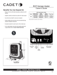
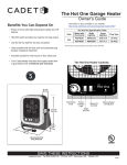
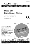
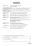
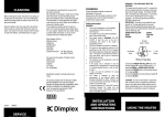
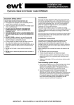
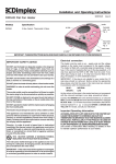
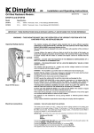
Installation and
Operating Instructions
Theme Radiant Convector Fuel Effect Fire
Model 316 CHE
T0102/004/A
Important Safety Advice
WARNING – THIS APPLIANCE MUST NOT BE USED IN A BATHROOM.
WARNING – DO NOT USE THIS HEATER IN THE IMMEDIATE
SURROUNDINGS OF A BATH, A SHOWER OR A SWIMMING POOL.
WARNING – THIS HEATER MUST NOT BE LOCATED IMMEDIATELY
BELOW A FIXED SOCKET OUTLET.
FOLLOW these instructions carefully.
THE HEATER CARRIES A WARNING ‘DO NOT COVER’ TO ALERT THE
USER TO THE RISK OF FIRE THAT EXISTS IF THE HEATER IS
ACCIDENTALLY COVERED.
WARNING – THE SAFETY GUARD ON THIS APPLIANCE CONFORMS
TO THE REQUIREMENTS OF BS1945 1971 AND SATISFIES THE
HEATING APPLIANCES (FIREGUARD) REGULATIONS 1978. THE
GUARD IS TO PREVENT THE RISK OF FIRE OR INJURY FROM BURNS
AND SHOULD NEVER BE REMOVED PERMANENTLY.
If young children, the aged or infirm are likely to be left in the vicinity of
the heater, we advise that adequate precautions should be taken. We
recommend that a guard be fitted to ensure contact with the heater is
avoided and objects cannot be inserted into the product.
For further information, please contact our guard supplier direct on
Tel No 01603 667957, or in case of difficulty or for further advice
contact the Customer Helpline – see page 4.
This heater is designed to meet the requirements of the relevant British
and European Standards for safety. However, we do not recommend its
use directly on deep pile carpets or long haired rugs.
CAUTION – DO NOT position curtains or furniture or other inflammable
materials closer than 1 metre (39") in front of this heater - see also page 2.
CAUTION – DO NOT use this heater where excessive dust or
moisture is present.
CAUTION – DO NOT use this heater in conjunction with an external
thermal control, a programme controller, a timer or any other device
which switches on the heater automatically, since a fire risk exists
when the heater is accidentally covered or displaced.
Preparing for use
Unpack the heater carefully and retain the packaging for future
use, in the event of moving or returning the heater to your supplier.
Always ensure that the heater is stood on a firm, level surface.
See also ‘Important Safety Advice’.
Electrical connection
WARNING – THIS APPLIANCE MUST BE EARTHED
This heater must be used on an
supply only and the voltage
marked on the heater must correspond to the supply voltage.
This heater is fitted with a rewirable plug incorporating a 13 amp
fuse. When replacing the fuse, a 13 amp fuse approved by ASTA
to BS 1362 must be used. If the plug is not suitable for your
socket, remove it and fit an appropriate plug.
IMPORTANT: If the plug is not suitable for your socket, the 13
amp plug should be removed. Before wiring the appropriate plug,
please note that the wires in this mains lead are coloured in
accordance with the following code:
BLUE – NEUTRAL
BROWN – LIVE
GREEN & YELLOW – EARTH
As the colours of the wires in the mains lead of this appliance may
not correspond with the coloured marking identifying the terminals
in your plug, proceed as follows:
Connect the BROWN wire to the terminal marked ‘L’ or coloured
RED.
Connect the BLUE wire to the terminal marked ‘N’ or coloured
BLACK.
Connect the GREEN & YELLOW wire to the terminal marked ‘E’
or ‘ ’ or coloured GREEN or GREEN & YELLOW.
If in doubt, consult an electrician.
IMPORTANT: If the mains lead is damaged, it must be
replaced by a special lead or assembly available from Dimplex
or an authorised Dimplex service agent.
Before switching on
Remove the fuel effect (two screws) and check that the lamps and
flicker rotors are positioned correctly – see Fig. 4, page 3.
The flicker rotors should sit horizontally on their pins and spin
freely without fouling their mounting brackets. If necessary, adjust
the bracket by bending slightly.
Refit the fuel effect by inserting the front edge first, then
secure it with the two screws.
Ensure that all packing items are removed (read any warning
labels carefully) and that the fuel effect and radiant elements are
positioned correctly, otherwise damage may occur.
Operating position
IMPORTANT — READ CAREFULLY AND RETAIN FOR FUTURE REFERENCE
IMPORTANT
ENSURE THAT THE HEATER IS POSITIONED IN ACCORDANCE WITH THE MINIMUM CLEARANCE DIMENSIONS GIVEN BELOW.
Shelf or
overhang
Curtains
300mm
300mm
min
610mm
Furniture or other obstruction
Wall curtains or furniture
300mm min
1000mm
min
265mm
775mm
Fig. 1
Operation
When you are certain that you have completed the installation,
plug in and switch on at the wall socket.
4
•
5
3
Controls
Fuel effect
The fuel effect will be lit all the time that the heater is connected to
the power supply, even if the heat selector switches are in the OFF
position. The flicker rotors should begin to rotate after a minute
or so.
The lamps will go out only when the heater is switched off at the
wall socket or unplugged.
2
1
Fig. 2
Radiant elements – see Fig. 2
You have a choice of low heat (two elements, 1332W) or high heat
(three elements, 1998W). Both settings have electronic
temperature control - see below.
A switch is set to ON when the red dot is visible.
5
MAX
4
MIN
Low heat setting
3
Press switch 1 to ON. Two elements will glow and, when the
temperature selected on the electronic control dial 3 is reached,
one of the elements will automatically turn off, switching back on if
the temperature falls.
See also ‘Electronic economiser temperature control ’ below.
4
1
5
2
6
Fig. 3
Convector Heater – see Fig. 3
High heat setting
The 800 watt convector heater can be used by itself for
background heating, or in conjunction with the radiant elements
for extra heat. The convector output is through the vent in the
canopy. This vent must never be covered or obstructed.
The convector heater is controlled by an ON/OFF switch 4 and
thermostat 5 located at the top right-hand side of the fire. The
output may be set to any position between MIN and MAX settings.
Set the switch to ON and set the thermostat to maximum setting
initially.
When the room is warm enough, turn the thermostat down slowly
until the convector heater just clicks off.
The thermostat will switch the convector ON and OFF to maintain
the selected temperature setting, as indicated by the pilot light 6.
In the MIN position, the convector will switch ON at a temperature
of approximately 5°C, to help protect against frosty conditions.
NOTE: If the convector heater does not come on when the
thermostat is set to a low number, this is normally because the
room is warmer than the thermostat setting and is not a fault.
Set switches 1 and 2 to ON. All three elements will glow and, when
the temperature selected on the electronic control dial 3 is
reached, two of the elements will automatically turn off, switching
back on if the temperature falls.
The fire can be returned to low heat setting by pressing switch 2
to OFF.
See also ‘Electronic economiser temperature control ’ below.
Electronic economiser temperature control
This sensitive output control 3 will switch the radiant heater
elements ON and OFF to accurately maintain the level of comfort
that you have selected.
Select low or high radiant setting – then turn the control dial to 7;
when the room reaches a comfortable level of warmth, turn the dial
down until the electronically controlled elements switch off. The
control dial should be left at this setting; the electronic control will
then switch the elements ON and OFF as needed to maintain your
chosen comfort level.
2
Maintenance
WARNING: ALWAYS DISCONNECT FROM THE MAINS SUPPLY BEFORE ATTEMPTING ANY MAINTENANCE
Access to flicker rotors and lamp replacement –
see Fig. 4
The fuel effect is secured by two screws, one at each end.
Slacken these screws (do not remove them completely) until the
fuel effect is released, then lift it clear. Ensure that the screws are
partially inserted into the fuel effect before refitting it.
Each flicker rotor should sit horizontally on its pin and spin freely
without fouling its mounting bracket. If necessary, adjust the
bracket by bending slightly (the plastic diffuser material is flexible).
To replace a lamp, bend up the defective lamp’s flicker rotor top
bracket arm carefully and lift off the rotor.
Replace the defective lamp with a 60 watt B22 fuel-effect lamp.
Reassemble in reverse order, ensuring that the diffuser/top
bracket arms are positioned correctly and the flicker rotors spin
freely.
Ensure flicker rotors
rotate freely on pins and that
lamps are in sockets correctly
Fig. 4
Removing the guard – see Fig. 5
Unscrew the two screws at each end of the guard, then withdraw
the lower edge of the guard first. Refit the guard in reverse order.
Fig. 5
Removing the radiant elements – see Fig. 6
First remove the guard, as detailed above.
The element holders are spring loaded. To remove an element,
grip one end using a soft cloth to protect the surface, then push
carefully but firmly to one side until the other end disengages from
its socket. Withdraw the element carefully. Refit in reverse order.
Fig. 6
Cleaning the reflector – see Fig. 7
The reflector may be more easily cleaned if the elements are first
removed (see above).
Wipe the reflector with a warm soapy cloth, then buff with a soft
dry cloth. DO NOT use abrasive cleaning powders or metal polish.
Fig. 7
3
Cleaning
After Sales Service
WARNING – ALWAYS DISCONNECT FROM THE POWER
SUPPLY BEFORE CLEANING THE HEATER.
Your appliance is guaranteed for 1 year from the date of purchase.
We undertake to repair or exchange, free of charge within the
guarantee period, any part found to be defective, excluding lamps.
Your rights under this guarantee are additional to your statutory
rights, which in turn are unaffected by this guarantee.
If your appliance is not working correctly, please contact our
Customer Helpline on 0870 727 0101.
This guarantee only applies in the United Kingdom.
Do not use detergents, abrasive cleaning powder or polish of any
kind on the body of the heater.
Allow the heater to cool, then wipe with a dry cloth to remove dust
and a damp cloth (not wet) to clean off stains. Be careful not to
allow moisture into the heater.
Specification subject to change without prior notice.
This appliance complies with European Safety Standards EN60335-2-30 and European
Standards EN55014, EN60555-2 and EN60555-3 for electromagnetic compatibility.
These standards cover the requirements of EEC Directives 73/23 and 89/336.
Glen Dimplex Heating Limited
Millbrook
Southampton
SO15 0AW
UK Customer Helpline (8am-6pm Mon-Fri; 8:30am-1pm Sat.)
Tel:
0870 727 0101
Fax:
0870 727 0102
T0102/004/A
Republic of Ireland: 01 842 4833
4