1
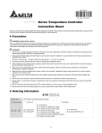
Note: SUB1 and SUB2 do not support DTE20L and DTE20C. Please install the optional output modules you purchase into
Operation altitude
< 2,000m
Ambient humidity
35% to 85% RH (non-condensing)
Pollution degree
2
the correct slot.
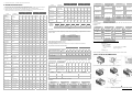
Communication Address of Output & How to Set up Parameters:
See Table 2 for the communication addresses of output and Table 3 for the definition of the value in the address.
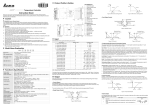
Product Profile & Outline!
INA
Series Temperature Controller
Instruction Sheet
DTE10T/P
Thank you very much for choosing Delta DTE series temperature controller. Please read this instruction sheet carefully before
using your DTE to ensure proper operation. Keep this instruction sheet handy for quick reference.
CH2
CH3
CH4
CH5
CH6
CH7
CH8
OUT1, OUT2
H10A8
H10A9
H10AA
H10AB
H10AC
H10AD
H10AE
H10AF
SUB1, SUB2
H10B0
H10B1
H10B2
H10B3
H10B4
H10B5
H10B6
H10B7
Table 2
I/O terminals
2
Status LED
3
Display and setup unit
DANGER! CAUTION! ELECTRIC SHOCK!
4
DIN rail clip
DTE is an OPEN-TYPE device and therefore should be installed in an enclosure free of airborne dust,
humidity, electric shock and vibration. The enclosure should prevent non-maintenance staff from
operating the device (e.g. key or specific tools are required for opening the enclosure) in case danger and
damage on the device may occur.
5
Power input port
6
RS-485 communication port
Table 3
7
Extension module fixing clip
8
Extension port
*When there are only 4 channels of inputs, SUB1 cannot be used for alarm output but heating/cooling control only.
**When there are only 4 channels of inputs, OUT2 and SUB2 cannot be set up by the user but set up automatically as "alarm
1. Prevent dust or metallic debris from falling into the device and cause malfunctions. DO NOT modify or uninstall the circuit
board of DTE without being permitted. DO NOT use empty terminals.
(a) dust or corrosive gas;
(b) high humidity and high radiation;
(c) shock and vibration.
3. The power has to be switched off when wiring or changing the temperature sensor.
Input
The standard DTE main unit is attached with 4 channels of inputs. You can purchase additional DTE20T or DTE20P to expand
the number of input channels. DTE supports maximum 8 channels of inputs which belong to group INA and group INB. Each
group possesses 4 input channels.
Input Sensor Type
Register Value
3
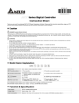
1: main unit
2: accessory
0T: 4-channel TC
0P: 4-channel PT
0T: 4-channel TC
0P: 4-channel PT
0V: 4 channels of voltage pulse output
0C: 4 channels of linear current output
0R: 4 channels of relay output
0L: 4 channels of linear voltage output
CT: 4 channels of current transformer sensors
DS: Display and setup module
Temperature measurement resistance (Cu50)
13
-50 ~ 150°C
Platinum resistance (Pt100)
12
-200 ~ 600°C
Platinum resistance (JPt100)
Thermocouple TXK type
Functions & Electrical Specifications!
Power input
DC 24V, isolated switching power supply
Voltage range
90% ~ 110% rated voltage
Power consumption
Max. 10W + 3W × number of DTC2000 controllers connected in parallel (Max. 7)
Input sensor
Thermocouple: K, J, T, E, N, R, S, B, L, U, TXK
Platinum resistance: Pt100, JPt100, Cu50
Sampling cycle
Thermocouple or platinum resistance: 1.0 second/all input
Control method
PID, PID programmable, manual, ON/OFF
Relay output: SPST, Max. AC 250V load, 3A resistive load
Output accessories
(optional)
Voltage pulse output: DC 24V, Max. 40mA current output
Current output: DC 4 ~ 20mA output (resistive load < 500Ω); for OUT1 and OUT2 only
11
For DTE10T / DTE20T
10
-20 ~ 400°C
-200 ~ 800°C
Thermocouple U type
9
-200 ~ 500°C
Thermocouple L type
8
-200 ~ 850°C
Thermocouple B type
7
100 ~ 1,800°C
Thermocouple S type
6
0 ~ 1,700°C
Thermocouple R type
5
0 ~ 1,700°C
Thermocouple N type
4
-200 ~ 1,300°C
Thermocouple E type
3
0 ~ 600°C
Thermocouple T type
2
-200 ~ 400°C
Thermocouple J type
1
-100 ~ 1,200°C
Thermocouple K type
0
-200 ~ 1,300°C
Communication address: Input sensor types at H10A0 ~ H10A7; input upper limits at H1010 ~ H1017; input lower limits at
H1018 ~ H101F.
Output
Without group INB (4 channels of input): Every channel corresponds to 2 groups of output and 2 groups of alarms. OUT1 and
SUB1 are for control output, and OUT1 can be used for proportional output. OUT2 and SUB2 are fixed for alarm output.
Output functions
Control output, alarm output or proportional output (proportional output is only applicable in
the model with linear voltage and current output for OUT1, OUT2)
See Table 1 for the relations between input and output.
Alarm modes
12 alarm modes available
Communication
RS-485 digital communication; supports baud rate 2,400bps ~ 115,200bps
Communication
protocol
4 channels of input
8 channels of input
INA (CH1 ~ CH4)
INA (CH1 ~ CH4)
INB (CH5 ~ CH8)
Supports Modbus ASCII/RTU
OUT1
Main control output or
proportional output
Main control output or proportional
output
No corresponding output
Extension port
The extension port transmits 24V power supply and communication signals to extension
module DTC2000.
OUT2
Alarm 1 output
No corresponding output
Main control output or proportional
output
Vibration resistance
10 ~ 55Hz
SUB1
Control output
Control output or alarm output
No corresponding output
Shock resistance
Max. 300m/s
SUB2
Alarm 2 output
No corresponding output
Control output or alarm output
Ambient temperature
0°C ~ +50°C
Storage temperature
-20°C ~ +65°C
2
10mins
3 axes 6 directions, 3 times each
Heating control
Cooling control
Alarm output*
Disable output
SV
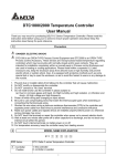
Alarm Mode
0
No alarm
Alarm output is enabled when the temperature reaches upper and lower
limits: The alarm will be enabled when PV exceeds SV + AL-H or falls below
SV – AL-L.
Alarm output will be enabled when the temperature reaches the upper limit:
The alarm will be enabled when the PV exceeds SV + AL-H.
3
Alarm output will be enabled when the temperature reaches the lower limit:
The alarm will be enabled when the PV falls below SV – AL-L.
4
Alarm output will be enabled when the PV is between SV + AL-H and SV –
AL-L.
Alarm output will be enabled when the temperature reaches the absolute
value of the upper and lower limits: The alarm will be enabled when the PV
exceeds AL-H or falls below AL-L.
Alarm output will be enabled when the temperature reaches the absolute
value of the upper limit: The alarm will be enabled when the PV exceeds
AL-H.
Alarm output will be enabled when the temperature reaches the absolute
value of the lower limit: The alarm will be enabled when the PV falls below
AL-L.
5
6
7
Upper/lower limit standby alarm: The alarm will be enabled when the PV
reaches SV and further exceeds SV + AL-H or falls below SV – AL-L.
8
9
Upper limit standby alarm: The alarm will be enabled when the PV reaches
SV and further exceeds SV + AL-H.
10
Lower limit standby alarm: The alarm will be enabled when the PV reaches
SV and further falls below SV – AL-L.
Upper limit hysteresis alarm: The alarm will be enabled when the PV exceeds
SV + AL-H. The alarm will be disabled when the PV falls below SV + AL-L.
11
12
Lower limit hysteresis alarm: The alarm will be enabled when the PV falls
below SV – AL-H. The alarm will be disabled when the PV exceeds SV –
AL-L.
Alarm Output Operation
Off
ON
OFF
AL-L
SV
AL-H
SV
AL-H
ON
OFF
ON
OFF
AL-L
SV
AL-L
SV
ON
OFF
AL-H
ON
OFF
AL-L
AL-H
ON
OFF
AL-H
ON
OFF
AL-L
ON
OFF
AL-L
SV
AL-H
SV
AL-H
ON
OFF
ON
OFF
AL-L
SV
ON
OFF
AL-L
AL-H
ON
OFF
AL-H
AL-L
PWR: On B DTE is powered.
RUN: On B Any of the channel is executing.
COM: Flashing B Communication in progress
ERR: Indicating errors (red)
ERR LED is on indicates one of the following errors occur, and the output has to be disabled.
1. Memory EEPROM error.
Output Group
3 axes
SUB1, SUB2**
LED Display
DTE supports maximum 16 channels of outputs, belonging to output groups OUT1, OUT2, SUB1 and SUB2, each group with 4
channels. See the explanations below for how input channels correspond to output groups.
With group INB (8 channels of input): Every channel is paired with 2 groups of outputs. OUT1 and OUT2 are used for control
output or proportional output of CH1 ~ CH8. SUB1 and SUB2 are used for control output or alarm output.
2
Disable output
Note: The default setting in DTE10T is “thermocouple K type”. The default setting in DTE10P is “Pt100".
Analog voltage output: 0 ~ 10V (resistive load > 1,000Ω); for OUT1 and OUT2 only
10m/s
Proportional output
Range
For DTE10P / DTE20P
Device type
Cooling control
2
DTE series supports the following input sensors:
DTE: Delta E series temperature controller
Heating control
1
8. DO NOT touch the terminal or repair the device when the power is on; otherwise an electric shock may occur.
Series name
OUT1, OUT2**
DTE offers 12 alarm modes. The alarm modes are set up at address H10C0 ~ H10C7, upper limits at H1080 ~ H1087 and
lower limits at H1088 ~ H108F.
7. Make sure the power cables and signal device are installed correctly before switching on the power; otherwise serious
damage may occur.
Ordering Information!
Value = 3
Alarm Output:
6. Keep the wire as short as possible when wiring a sensor to the controller. Separate the power cable and load wire in order
to prevent interference and induced noise.
11. Please place DTE with other heating objects (e.g. power supply) within proper distance while installing DTE.
Value = 2
DTE offers PID control, ON/OFF control, manual control and programmable PID control. Control output methods are set at
address H10B8 ~ H10BF (default = 0: PID), PID parameters at H1028 ~ H105F, ON/OFF parameters at H1058 ~ H106F, and
manual control parameters at H1070 ~ H107F.
Panel Layout!
5. Make sure to use compensation wire which matches the thermocouple or platinum resistance when extending or
connecting the thermocouple or platinum resistance.
10. DO NOT touch the internal terminal when DTE is either switched on or off in case you may damage the circuit.
Value = 1
Control Output:
4. When installing the circuit board of the accessory, please make sure the power of the main unit is switched off and insert
the accessory into the correct slot on the main unit.
9. Please wait for 1 minute after the power is switched off to allow the capacitor to discharge and DO NOT touch the internal
wiring within this period.
Value = 0
output” by the controller.
2. Keep away from high-voltage and high-frequency environment during the installation in case of interference. Prevent using
the device in premises which contain:
2
CH1
1
Warning
1
INB
Table 1
2. Any of the input points is not connected.
3. Any of the input points exceeds the setup range.
4. Any of the input temperatures has not been stabilized.
Synchronous Communication Protocol & Auto ID Setup
This function allows the auto setup of communication protocol in extension module DTC2000 and DTC2001 following the
communication protocol set in the DTE main unit. The station IDs of DTC decrease. See below for the steps.
1. Set the auto communication ID of DTE as “1” (communication address: H10F8).
2. Switch off DTE. Connect DTE with extension module DTC2000, DTC2001 and switch on DTE again.
3. Default communication protocol: 9,600bps, 7 bits, Even, 1 stop bit, communication address = 01.
4. This function will consume 3 ~ 5 seconds more when you switch on DTE.
INA
RS-485 Communication
Content
1. DTE supports baud rates 2,400/4,800/9,600/19,200/38,400/57,600/115,200 bps and does not support communication
format 7, N, 1/8, E, 2/8, O, 2. Communication protocol = Modbus ASCII or RTU.
2. Function codes: H03 = read maximum 8 words in the register; H06 = write 1 word into the register.
3. Address and contents: Every parameter has 2 communication addresses. One is numbered by the function of the
parameter, and the other is by the order of channel (as shown in the table below).
INA
Content
Present
temperature
value/input error
code
Explanation
Unit; 0.1
See Table 5
CH1
CH2
INB
CH3
CH4
CH5
CH6
CH7
CH8
H1000 H1001 H1002 H1003 H1004 H1005 H1006 H1007
(H1100) (H1200) (H1300) (H1400) (H1500) (H1600) (H1700) (H1800)
H1008 H1009 H100A H100B H100C H100D H100E H100F
(H1101) (H1201) (H1301) (H1401) (H1501) (H1601) (H1701) (H1801)
Set temperature
value
Unit: 0.1
Max. temperature
value
Disabled when higher H1010 H1011 H1012 H1013 H1014 H1015 H1016 H1017
than default value
(H1102) (H1202) (H1302) (H1402) (H1502) (H1602) (H1702) (H1802)
Min. temperature
value
Disabled when lower H1018 H1019 H101A H101B H101C H101D H101E H101F
than default value
(H1103) (H1203) (H1303) (H1403) (H1503) (H1603) (H1703) (H1803)
Error temperature
value
-999 ~ +999
Unit: 0.1°C
H1020 H1021 H1022 H1023 H1024 H1025 H1026 H1027
(H1104) (H1204) (H1304) (H1404) (H1504) (H1604) (H1704) (H1804)
Proportional band
value (Pb)
0 ~ 9,999
Unit: 0.1
H1028 H1029 H102A H102B H102C H102D H102E H102F
(H1105) (H1205) (H1305) (H1405) (H1505) (H1605) (H1705) (H1805)
Ti value
0 ~ 9,999
H1030 H1031 H1032 H1033 H1034 H1035 H1036 H1037
(H1106) (H1206) (H1306) (H1406) (H1506) (H1606) (H1706) (H1806)
Td value
0 ~ 9,999
H1038 H1039 H103A H103B H103C H103D H103E H103F
(H1107) (H1207) (H1307) (H1407) (H1507) (H1607) (H1707) (H1807)
0.0 ~ 100.0%
Unit: 0.1%
H1040 H1041 H1042 H1043 H1044 H1045 H1046 H1010
(H1108) (H1208) (H1308) (H1408) (H1508) (H1608) (H1708) (H1808)
Proportional control
0.0 ~ 100.0%
offset error value,
Unit: 0.1%
when Ti = 0
H1048 H1049 H104A H104B H104C H104D H104E H104F
(H1109) (H1209) (H1309) (H1409) (H1509) (H1609) (H1709) (H1809)
Proportional band
0.01 ~ 99.99
coefficient of output
Unit: 0.01
1 and output 2
H1050 H1051 H1052 H1053 H1054 H1055 H1056 H1057
(H110A) (H120A) (H130A) (H140A) (H150A) (H160A) (H170A) (H180A)
Dead band of
control output 1 &
output 2.
-99.9 ~ 999.9
H1058 H1059 H105A H105B H105C H105D H105E H105F
(H110B) (H120B) (H130B) (H140B) (H150B) (H160B) (H170B) (H180B)
Hysteresis for
output 1
0 ~ 9,999
Unit: 0.1%
H1060 H1061 H1062 H1063 H1064 H1065 H1066 H1067
(H110C) (H120C) (H130C) (H140C) (H150C) (H160C) (H170C) (H180C)
Hysteresis for
output 2
0 ~ 9,999
Unit: 0.1%
H1068 H1069 H106A H106B H106C H106D H106E H106F
(H110D) (H120D) (H130D) (H140D) (H150D) (H160D) (H170D) (H180D)
Unit: 0.1 %
H1070 H1071 H1072 H1073 H1074 H1075 H1076 H1077
(H110E) (H120E) (H130E) (H140E) (H150E) (H160E) (H170E) (H180E)
Integration default
Read/write output
1 value
Explanation
Run/Stop the
control
Status of PID
auto-tuning
CH1
CH2
CH3
CH4
CH5
CH6
CH7
H10D8 H10D9 H10DA H10DB H10DC H10DD H10DE H10DF
(H111B) (H121B) (H131B) (H141B) (H151B) (H161B) (H171B) (H181B)
0: stop
1: executing
H10E0 H10E1 H10E2 H10E3 H10E4 H10E5 H10E6 H10E7
(H111C) (H121C) (H131C) (H141C) (H151C) (H161C) (H171C) (H181C)
0: positive
1: negative (slope)
Other statuses
Other statuses
H10E8 H10E9 H10EA H10EB H10EC H10ED H10EE H10EF
(H111D) (H121D) (H131D) (H141D) (H151D) (H161D) (H171D) (H181D)
H10F1
H10F0
H10F2
Open special
Temperature
function
unit
Return to
default
(H1234) (H1357)
H10F8
See Table 4
Auto ID
setup
H10F9
H10FA
Reserved
Baud rate
H10F3
H10F4
H10F5
H10F6
H10F7
Reserved
Reserved
Reserved
Reserved
Reserved
H10FB
H10FC
H10FD
ASCII = 0
RTU = 1
8 bits=0
7 bits=1
2 stop=0
1 stop=1
H10FE
Parity
H10FF
Read start address of
data/bit
‘0’
Length of response data
(byte)
‘0’
‘0’
‘0’
‘0’
‘4’
‘0’
Data content in H1000
Write Command
Write Response Message
‘1’
Data address
‘0’
‘0’
‘0’
‘1’
‘1’
‘1’
‘0’
‘F’
‘0’
‘0’
‘4’
‘3’
‘0’
‘0’
LRC1 check
‘E’
LRC0 check
‘A’
End word 1
CR
End word 0
LF
Data content in H1001
Data address
‘0’
Read length of data/bit
(word/bit)
‘2’
‘1’
Write data content
‘0’
‘E’
Write data content
‘8’
‘3’
‘E’
‘8’
‘0’
LRC1 check
‘F’
LRC1 check
‘F’
‘0’
LRC0 check
‘D’
LRC0 check
‘D’
LRC1 check
‘0’
End word 1
CR
End word 1
CR
LRC0 check
‘3’
End word 0
LF
End word 0
LF
End word 1
CR
End word 0
LF
LRC Check:
Communication Parameter Setting:
Sum up the contents from “machine address” to “data content”, e.g. H01 + H03 + H10 + H00 + H00 + H02 = H16. Obtain
2’scomplement H EA.
Content
0
1
2
3
4
5
6
Baud rate
2,400bps
4,800bps
9,600bps
19,200bps
38,400bps
57,600bps
115,200bps
Parity bit
None (N)
Even (E)
Odd (O)
RTU Mode:
Read Command
Table 4
Error Codes:
The error codes can be read from address H1000 ~ H1007. When the input operation is in normal status, H1000 ~ H1007 are
for input values. When input error occurs (except for stable status and input exceeding the range), DTE will read error codes
in H8001 ~ H8002.
H1000
Error description
H8001
EEPROM cannot be written in.
H8002
Input sensor is not connected.
H8003
Group INB is not connected.
Read Response Message
Write Command
Write Response Message
Machine address
H01
Machine address
H01
Machine address
H01
Machine address
H01
Command
H03
Command
H03
Command
H06
Command
H06
Read start address of
data
H10
Read length of data
(bit/word)
H00
CRC low byte
HC0
CRC high byte
HCB
H00
H02
Length of response
data (byte)
Data content 1
Data content 2
H04
H01
HF4
Write data address
Write data content
H10
H01
H03
H20
Write data address
Write data content
H10
H01
H03
H20
H03
CRC low byte
HDD
CRC low byte
HDD
H20
CRC high byte
HE2
CRC high byte
HE2
CRC low byte
HBB
CRC high byte
H15
Table 5
CRC (Cyclical Redundancy Check) is obtained by the following steps:
Analog output current tuning scale: 1μA/scale
Analog output voltage tuning scale: 1mV/scale
Returning to Default Value: Write H1234 into address H10F1 and H1357 into address H10F2. Restart DTE.
Programmable Communication Parameter Setting:
INA
Content
Explanation
INB
CH1
CH2
CH3
CH4
CH5
CH6
CH7
CH8
unsigned int reg_crc = 0xffff;
i = 0;
while (length--)
{ reg_crc ^= RTUData[i];
i ++;
for (j = 0; j < 8; j++)
{ if (reg_crc & 0x01)
else
}
}
return(reg_crc);
reg_crc = (reg_crc >> 1) ^ 0xA001;
reg_crc = reg_crc >> 1;
Read remaining time of the step
Unit: sec
H111E
H121E
H131E
H141E
H151E
H161E
H171E
H181E
Unit: min
H111F
H121F
H131F
H141F
H151F
H161F
H171F
H181F
Software for Setting up Communication on PC: Download the free software on Delta’s website.
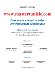
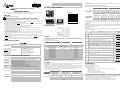
How to Mount & DIN Rail Size
Read/write output
2 value
Unit: 0.1 %
H1078 H1079 H107A H107B H107C H107D H107E H107F
(H110F) (H120F) (H130F) (H140F) (H150F) (H160F) (H170F) (H180F)
0~7
H1120
H1220
H1320
H1420
H1520
H1620
H1720
H1820
Upper limit for
alarm output
Alarm enabled
when temperature
exceeds upper limit
Read the NO. of the current
pattern
H1080
(H1110)
Read the NO. of the current step
0~7
H1121
H1221
H1321
H1421
H1521
H1621
H1721
H1821
Lower limit for
alarm output
Alarm enabled
when temperature
falls below lower
limit
H1088 H1089 H108A H108B H108C H108D H108E H108F
(H1111) (H1211) (H1311) (H1411) (H1511) (H1611) (H1711) (H1811)
Tuning for upper
limit of analog
output
Current (4 ~ 20mA)
or voltage output
tuning
H1090 H1091 H1092 H1093 H1094 H1095 H1096 H1097
(H1112) (H1212) (H1312) (H1412) (H1512) (H1612) (H1712) (H1812)
Tuning for lower
limit of analog
output
Current (4 ~ 20mA)
or voltage output
tuning
H1098 H1099 H109A H109B H109C H109D H109E H109F
(H1113) (H1213) (H1313) (H1413) (H1513) (H1613) (H1713) (H1813)
Input sensor type
See “Input” section
H10A0 H10A1 H10A2 H10A3 H10A4 H10A5 H10A6 H10A7
(H1114) (H1214) (H1314) (H1414) (H1514) (H1614) (H1714) (H1814)
Output function
for output 1
0: heating
1: cooling
2: proportional
output
H10A8 H10A9 H10AA H10AB H10AC H10AD H10AE H10AF
(H1115) (H1215) (H1315) (H1415) (H1515) (H1615) (H1715) (H1815)
Output function
for output 2
0: heating (default)
1: cooling
2: alarm
H10B0 H10B1 H10B2 H10B3 H10B4 H10B5 H10B6 H10B7
(H1116) (H1216) (H1316) (H1416) (H1516) (H1616) (H1716) (H1816)
Control method
0: PID
1: ON-OFF
2: manual
3: PID
programmable
H10B8 H10B9 H10BA H10BB H10BC H10BD H10BE H10BF
(H1117) (H1217) (H1317) (H1417) (H1517) (H1617) (H1717) (H1817)
Alarm 1 output
mode
See “Alarm Output”
section
H10C0 H10C1 H10C2 H10C3 H10C4 H10C5 H10C6 H10C7
(H1118) (H1218) (H1318) (H1418) (H1518) (H1618) (H1718) (H1818)
Alarm 2 output
mode
See “Alarm Output”
section
H10C4 H10C5 H10C6 H10C7
(H1518) (H1618) (H1718) (H1818)
Start word
’:’
Start word
’:’
Start word
’:’
Start word
’:’
Heating/cooling
cycle for output 1
1 ~ 99 seconds
0 = 0.5 second
H10C8 H10C9 H10CA H10CB H10CC H10CD H10CE H10CF
(H1119) (H1219) (H1319) (H1419) (H1519) (H1619) (H1719) (H1819)
Machine address 1
‘0’
Machine address 1
‘0’
Machine address 1
‘0’
Machine address 1
‘0’
Machine address 0
‘1’
Machine address 0
‘1’
Machine address 0
‘1’
Machine address 0
‘1’
Heating/cooling
cycle for output 2
1 ~ 99 seconds
0 = 0.5 second
H10D0 H10D1 H10D2 H10D3 H10D4 H10D5 H10D6 H10D7
(H111A) (H121A) (H131A) (H141A) (H151A) (H161A) (H171A) (H181A)
Command 1
‘0’
Command 1
‘0’
Command 1
‘0’
Command 1
‘0’
Command 0
‘3’
Command 0
‘3’
Command 0
‘6’
Command 0
‘6’
H1082 H1083 H1084 H1085 H1086 H1087
(H1310) (H1410) (H1510) (H1610) (H1710) (H1810)
‘1’
Address
1 ~ 247
Read remaining time of the step
H1081
(1210)
Read Response Message
CH8
0: stop
1: executing
2: program stops
3: program pauses
Positive/negative
proportional
output
Communication
specifications
Read Command
INB
NO. of start pattern
0~7
H1122
H1222
H1322
H1422
H1522
H1622
H1722
H1822
NO. of start step
0~7
H1123
H1223
H1323
H1423
H1523
H1623
H1723
H1823
Programmable Parameter Setting:
Content
Explanation
Pattern Pattern Pattern Pattern Pattern Pattern Pattern Pattern
0
1
2
3
4
5
6
7
Max. number of
steps in the pattern
0 ~ 7 = N: The pattern
executes from step 0 to
N.
H2068
H2069
H206A
H206B
H206C H206D
H206E
H206F
Number of cycles of
pattern 0 ~ 7
execution
0 ~ 199: The pattern
has been executed for 1
~ 200 times
H2070
H2071
H2072
H2073
H2074
H2075
H2076
H2077
NO. of current link
pattern
0 ~ 8: 8 refers to end of
program; 0 ~ 7 refer to
the NO. of next pattern
H2078
H2079
H207A
H207B
H207C H207D
H207E
H207F
Address
Default
Content
Connect maximum 7 DTC2000 or DTC2001 controllers to DTE by using DIN rail.
Explanation
2000H ~ 203FH
0
Target temperatures for pattern 0 ~ 7
Pattern 0: 2000H ~ 2007H
Unit: 0.1°C
2080H ~ 20BFH
0
Execution time for pattern 0 ~ 7
Pattern 0: 2080H ~ 2087H
Time: 0 ~ 900 (Unit: 1 min)
4. Communication format: H03 = read bit data; H06 = write bit data
ASCII Mode:
Read Command
Read Response Message
Write Command
Write Response Message
The content of this instruction sheet may be revised without prior notice. Please consult our distributor or
download the most updated version at http://www.delta.com.tw/industrialautomation.