1
Series Temperature Controller
Instruction Sheet
Thank you very much for choosing Delta DTE series temperature controller. Please read this instruction sheet carefully before using your DTE
to ensure proper operation. Keep this instruction sheet handy for quick reference.
Precaution
DANGER! Caution! Electric Shock!
DTE is an OPEN-TYPE device and therefore should be installed in an enclosure free of airborne dust, humidity, electric shock and vibration.
The enclosure should prevent non-maintenance staff from operating the device (e.g. key or specific tools are required for opening the
enclosure) in case danger and damage on the device may occur.
WARNING!
1. Prevent dust or metallic debris from falling into the device and cause malfunctions. DO NOT modify or uninstall the circuit board of DTE
without being permitted. DO NOT use empty terminals.
2. Keep away from high-voltage and high-frequency environment during the installation in case of interference. Prevent using the device in
premises which contain:
(a) dust or corrosive gas;
(b) high humidity and high radiation;
(c) shock and vibration.
3. The power has to be switched off when wiring or changing the temperature sensor.
4. When installing the circuit board of the accessory, please make sure the power of the main unit is switched off and insert the accessory
into the correct slot on the main unit.
5. Make sure to use compensation wire which matches the thermocouple or platinum resistance when extending or connecting the
thermocouple or platinum resistance.
6. Keep the wire as short as possible when wiring a sensor to the controller. Separate the power cable and load wire in order to prevent
interference and induced noise.
7. Make sure the power cables and signal device are installed correctly before switching on the power; otherwise serious damage may
occur.
8. DO NOT touch the terminal or repair the device when the power is on; otherwise an electric shock may occur.
9. Please wait for 1 minute after the power is switched off to allow the capacitor to discharge and DO NOT touch the internal wiring within
this period.
10. DO NOT touch the internal terminal when DTE is either switched on or off in case you may damage the circuit.
11. Please place DTE with other heating objects (e.g. power supply) within proper distance while installing DTE.
Ordering Information
Series name
1
2
DTE: Delta E series temperature controller
Device type
3
-
4
1: main unit
0T: 4-channel TC
0P: 3-channel PT
2: accessory
0T: 4-channel TC
0V: 4 channels of voltage pulse output
0C: 4 channels of linear current output
0R: 4 channels of relay output
0L: 4 channels of linear voltage output
CT: 4 channels of current transformer sensors
DS: Display and setup module
-1-
0P: 3-channel PT
0D: 8-channel EVENT input
Specifications
Power input
24 VDC, isolated switching power supply
Voltage range
90 to 110% rated voltage
Power consumption
Max. 10 W + 3 W × number of DTC2000 controllers connected in parallel (Max. 7)
Input sensor
Thermocouple: K, J, T, E, N, R, S, B, L, U, TXK
Platinum resistance: Pt100, JPt100, Cu50
Sampling cycle
Thermocouple or platinum resistance: 1.0 second/all input
Control method
PID, PID programmable, manual, ON/OFF
Relay output: SPST, Max. 250 VAC load, 3 A resistive load
Output accessories
(optional)
Voltage pulse output: 12 VDC, Max. 40 mA current output
Current output: DC 4 to 20 mA output (resistive load < 500Ω); for OUT1 and OUT2 only
Analog voltage output: 0 to 10V (resistive load > 1,000Ω); for OUT1 and OUT2 only
Output functions
Control output, alarm output or proportional output (proportional output is only applicable in the model with
linear voltage and current output for OUT1, OUT2)
Alarm modes
13 alarm modes available
Communication
RS-485 digital communication; supports baudrate 2,400 to 115,200bps
Communication protocol
Supports Modbus ASCII/RTU
Extension port
The extension port transmits 24V power supply and communication signals to extension module DTC2000.
Vibration resistance
10 to 55Hz
10m/s
Shock resistance
Max. 300m/s
2
Ambient temperature
0 to +50°C
2
3 axes
10mins
3 axes 6 directions, 3 times each
Storage temperature
-20 to +65°C
Operation altitude
< 2,000m
Ambient humidity
35 to 85% RH (non-condensing)
Pollution degree
2
Product Profile & Outline
DTE10T
Panel Layout!
-2-
1
I/O terminals
2
Status LED
3
Display and setup unit
4
DIN rail clip
5
Power input port
6
RS-485 communication port
7
Extension module fixing clip
8
Extension port
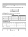
Input
The standard DTE main unit is attached with 4 channels of inputs. You can purchase additional DTE20T or DTE20P to expand the number of
input channels. DTE supports maximum 8 channels of inputs which belong to group INA and group INB. Each group possesses 4 input
channels.
DTE series supports the following input sensors:
Input Sensor Type
Register Value
Range
For DTE10P / DTE20P
Temperature measurement resistance (Cu50)
13
-50 ~ 150°C
Platinum resistance (Pt100)
12
-200 ~ 600°C
11
-20 ~ 400°C
Platinum resistance (JPt100)
For DTE10T / DTE20T
Thermocouple TXK type
10
Thermocouple U type
9
-200 ~ 800°C
-200 ~ 500°C
Thermocouple L type
8
-200 ~ 850°C
Thermocouple B type
7
100 ~ 1,800°C
Thermocouple S type
6
0 ~ 1,700°C
Thermocouple R type
5
0 ~ 1,700°C
Thermocouple N type
4
-200 ~ 1,300°C
Thermocouple E type
3
0 ~ 600°C
Thermocouple T type
2
-200 ~ 400°C
Thermocouple J type
1
-100 ~ 1,200°C
Thermocouple K type
0
-200 ~ 1,300°C
Note: The default setting in DTE10T is “thermocouple K type”. The default setting in DTE10P is “Pt100".
Communication address: Input sensor types at H10A0 ~ H10A7; input upper limits at H1010 ~ H1017; input lower limits at H1018 ~ H101F.
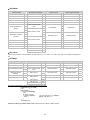
Output
DTE supports maximum 16 channels of outputs, belonging to output groups OUT1, OUT2, SUB1 and SUB2, each group with 4 channels. See
the explanations below for how input channels correspond to output groups.
Without group INB (4 channels of input): Every channel corresponds to 2 groups of output and 2 groups of alarms. OUT1 and SUB1 are for
control output, and OUT1 can be used for proportional output. OUT2 and SUB2 are fixed for alarm output.
With group INB (8 channels of input): Every channel is paired with 2 groups of outputs. OUT1 and OUT2 are used for control output or
proportional output of CH1 ~ CH8. SUB1 and SUB2 are used for control output or alarm output.
See Table 1 for the relations between input and output.
4 channels of input
8 channels of input
Output Group
INA (CH1 ~ CH4)
INA (CH1 ~ CH4)
INB (CH5 ~ CH8)
OUT1
Main control output or
proportional output
Main control output or
proportional output
No corresponding output
OUT2
Alarm 1 output
No corresponding output
Main control output or
proportional output
SUB1
Control output
Control output or alarm output
No corresponding output
SUB2
Alarm 2 output
No corresponding output
Control output or alarm output
Table 1
Note: SUB1 and SUB2 do not support DTE20L and DTE20C. Please install the optional output modules you purchase into the correct slot.
Communication Address of Output & How to Set up Parameters
See Table 2 for the communication addresses of output and Table 3 for the definition of the value in the address.
INA
INB
CH1
CH2
CH3
CH4
CH5
CH6
CH7
CH8
OUT1, OUT2
H10A8
H10A9
H10AA
H10AB
H10AC
H10AD
H10AE
H10AF
SUB1, SUB2
H10B0
H10B1
H10B2
H10B3
H10B4
H10B5
H10B6
H10B7
Table 2
-3-
Value = 0
Value = 1
Value = 2
Value = 3
OUT1, OUT2**
Heating control
Cooling control
Proportional output
Disable output
SUB1, SUB2**
Heating control
Cooling control
Alarm output*
Disable output
Table 3
*When there are only 4 channels of inputs, SUB1 cannot be used for alarm output but heating/cooling control only.
**When there are only 4 channels of inputs, OUT2 and SUB2 cannot be set up by the user but set up automatically as "alarm output” by the
controller.
Control Output
DTE offers PID control, ON/OFF control, manual control and programmable PID control. Control output methods are set at address H10B8 ~
H10BF (default = 0: PID), PID parameters at H1028 ~ H105F, ON/OFF parameters at H1058 ~ H106F, and manual control parameters at
H1070 ~ H107F.
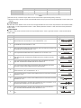
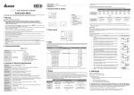
Alarm Output
DTE offers 13 alarm modes. The alarm modes are set up at address H10C0 ~ H10C7, upper limits at H1080 ~ H1087 and lower limits at
H1088 ~ H108F.
SV
0
1
2
3
Alarm Mode
Alarm Output Operation
No alarm
Off
Alarm output is enabled when the temperature reaches upper and lower limits: The alarm
will be enabled when PV exceeds SV + AL-H or falls below SV – AL-L.
Alarm output will be enabled when the temperature reaches the upper limit: The alarm will
be enabled when the PV exceeds SV + AL-H.
Alarm output will be enabled when the temperature reaches the lower limit: The alarm will
be enabled when the PV falls below SV – AL-L.
4
Alarm output will be enabled when the PV is between SV + AL-H and SV – AL-L.
5
Alarm output will be enabled when the temperature reaches the absolute value of the
upper and lower limits: The alarm will be enabled when the PV exceeds AL-H or falls
below AL-L.
6
7
8
9
10
11
Alarm output will be enabled when the temperature reaches the absolute value of the
upper limit: The alarm will be enabled when the PV exceeds AL-H.
Alarm output will be enabled when the temperature reaches the absolute value of the
lower limit: The alarm will be enabled when the PV falls below AL-L.
Upper/lower limit standby alarm: The alarm will be enabled when the PV reaches SV and
further exceeds SV + AL-H or falls below SV – AL-L.
Upper limit standby alarm: The alarm will be enabled when the PV reaches SV and further
exceeds SV + AL-H.
Lower limit standby alarm: The alarm will be enabled when the PV reaches SV and further
falls below SV – AL-L.
Upper limit hysteresis alarm: The alarm will be enabled when the PV exceeds SV + AL-H.
The alarm will be disabled when the PV falls below SV + AL-L.
12
Lower limit hysteresis alarm: The alarm will be enabled when the PV falls below SV –
AL-H. The alarm will be disabled when the PV exceeds SV – AL-L.
13
CT alarm: The alarm will be enabled when the CT value exceeds AL-H or falls below
AL-L.
-4-
ON
OFF
AL-L
SV
AL-H
SV
AL-H
ON
OFF
ON
OFF
AL-L
SV
AL-L
SV
ON
OFF
AL-H
ON
OFF
AL-L
AL-H
ON
OFF
AL-H
ON
OFF
AL-L
ON
OFF
AL-L
SV
AL-H
SV
AL-H
ON
OFF
ON
OFF
AL-L
SV
ON
OFF
AL-L
AL-H
ON
OFF
AL-H
AL-L
ON
OFF
AL-L
AL-H
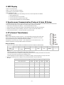
LED Display
PWR: On DTE is powered.
RUN: On Any of the channel is executing.
COM: Flashing Communication in progress
ERR: Indicating errors (red)
ERR LED is on indicates one of the following errors occur, and the output has to be disabled.
1. Memory EEPROM error.
2. Any of the input points is not connected.
3. Any of the input points exceeds the setup range.
4. Any of the input temperatures has not been stabilized.
Synchronous Communication Protocol & Auto ID Setup
This function allows the auto setup of communication protocol in extension module DTC2000 and DTC2001 following the communication
protocol set in the DTE main unit. The station IDs of DTC decrease. See below for the steps.
1. Set the auto communication ID of DTE as “1” (communication address: H10F8).
2. Switch off DTE. Connect DTE with extension module DTC2000, DTC2001 and switch on DTE again.
3. Default communication protocol: 9,600bps, 7 bits, Even, 1 stop bit, communication address = 01.
4. This function will consume 3 ~ 5 seconds more when you switch on DTE.
CT (Current Transformer)
Function
DTE10T offers maximum 4 channels of CT (CT1 ~ CT4), responsible for monitoring the current in INA.
Each CT group can be set up independently. With alarm outputs, when the detected current value is
beyond the allowed range, the corresponding alarm will be enabled.
Slot INA offers 4 channels of input, and CH1 ~ CH4 correspond to the current detected at CT1 ~ CT4.
Hardware requirement: Accessory DTE2CT inserted in the slot AUX.
How to Operate
1. Enable the CT function: Write 1234H into the address 47F1H and then 0004H into address 4824H.
bits in 4824H
Bit7
Bit6
Bit5
Bit4
Bit3
Bit2
Bit1
Bit0
Flag
--
Hot runner
control
Slope control
--
Latch
CT
EVENT
--
Notes:
The flag to enable CT is at bit2 of 4824H. Write 0004H to bit2 to set it on.
If the “multistate” function is enabled, for example, writing in 0024H means enabling bit5 and bit2 at the same time.
You can only choose to use either the CT or EVENT function.
If there is already a set value in 4824H and you would like to modify it, reset it to 0 before you set up a new value.
2. When you use INA input or INA + INB input, set up relevant parameters using the table below.
INA input:
INA
CH1
CH2
CH3
CH4
OUT1 control mode
10A8H
10A9H
10AAH
10ABH
OUT2 control mode
10B0H
10B1H
10B2H
10B3H
Alarm 1 output mode
10C0H
10C1H
10C2H
10C3H
Alarm 2 output mode
10C4H
10C5H
10C6H
10C7H
Upper bound of Alarm 1 output
1080H
1081H
1082H
1083H
Lower bound of Alarm 1 output
1088H
1089H
108AH
108BH
Upper bound of Alarm 2 output
1084H
1085H
1086H
1087H
Lower bound of Alarm 2 output
108CH
108DH
108EH
108FH
CT value (latch)
19A0H
19A1H
19A2H
19A3H
CT value (dynamic)
19A4H
19A5H
19A6H
19A7H
-5-
INA + INB input:
INA+INB
CH1
CH2
CH3
CH4
CH5
CH6
CH7
CH8
OUT1 control mode
10A8H
10A9H
10AAH
10ABH
10ACH
10ADH
10AEH
10AFH
Alarm 1 output mode
10C0H
10C1H
10C2H
10C3H
10C4H
10C5H
10C6H
10C7H
Upper bound of Alarm 1 output
1080H
1081H
1082H
1083H
1084H
1085H
1086H
1087H
Lower bound of Alarm 1 output
1088H
1089H
108AH
108BH
108CH
108DH
108EH
108FH
CT value (latch)
19A0H
19A1H
19A2H
19A3H
--
--
--
--
CT value (dynamic)
19A4H
19A5H
19A6H
19A7H
--
--
--
--
3.
4.
5.
6.
OUT1 control mode has to be set to “0” (heating) or “1” (cooling). It cannot be set to “2” (proportional output).
You can select Alarm 1 or Alarm 2 to be the output contact. The output mode has to be set to “13” (000DH).
Adjust the upper/lower bound of the alarm output.
The CT value will only be measured when there is OUT1 executing. If OUT1 does not exist, the previous CT value measured will be
displayed.
EVENT Input
Function
DTE10T offers 8 channels of EVENT input (EV1 ~ EV8), and each EVENT can be
set up independently. Slot number 1 ~ 8 in AUX on DTE10T correspond to EV1 ~ EV8.
EV1 to EV8 can be short-circuited individually with slot number 9 to switch functions.
Hardware requirement: Accessory DTE20D inserted in the slot AUX.
How to Operate
1. Enable the EVENT function: Write 1234H into the address 47F1H and then 0002H into address 4824H.
bits in 4824H
Flag
Bit7
Bit6
Bit5
Bit4
Bit3
Bit2
Bit1
Bit0
--
Hot runner
control
Slope control
--
Latch
CT
EVENT
--
Notes:
The flag to enable EVENT is at bit1 of 4824H. Write 0002H to bit1 to set it on.
If the “multistate” function is enabled, for example, writing in 0022H means enabling bit5 and bit1 at the same time.
You can only choose to use either the CT or EVENT function.
If there is already a set value in 4824H and you would like to modify it, reset it to 0 before you set up a new value.
2. Each channel can be set up individually for specific functions.
Addresses:
CH
CH1
CH2
CH3
CH4
CH5
CH6
CH7
CH8
Address for the
EVENT function
1998H
1999H
199AH
199BH
199CH
199DH
199EH
199FH
Functions:
Set value
Function
0
1
2
3
4
N/A
RUN (open circuit)
STOP (short circuit)
SV1 (open circuit)
SV2 (short circuit)
Auto (open circuit)
Manual (short circuit)
Execute (open circuit)
Pause (short circuit)
Definitions:
RUN/STOP: To enable or disable the output.
SV1/SV2: To switch between set values.
Auto/manual: To switch between the PID and manual controls.
Execute/pause: To execute or pause the counting time when in programmable PID control.
Example: If you would like the function of EVENT1 at CH1 to be “SV1/SV2”, write 0002H into address 1998H.
Slope
Function
The temperature rises according to the slope set. Unit: 0.1°C/min.
Example: Suppose the slope is set to “50” and SV “200.0°C”, then the temperature will rise at 5°C per minute until it reaches 200.0°C.
-6-
How to Operate
1. Enable the slope function: Write 1234H into the address 47F1H and then 0020H into address 4824H.
bits in 4824H
Bit7
Bit6
Bit5
Bit4
Bit3
Bit2
Bit1
Bit0
--
Hot runner
control
Slope control
--
Latch
CT
EVENT
--
Flag
Notes:
The flag to enable slope function is at bit5 of 4824H. Write 0020H to bit5 to set it on.
If the “multistate” function is enabled, for example, writing 0022H means enabling bit5 and bit1 at the same time.
If there is already a set value in 4824H and you would like to modify it, reset it to 0 before you set up a new value.
2. Set up relevant parameters using the table below.
CH
CH1
CH2
CH3
CH4
CH5
CH6
CH7
CH8
Set value (SV)
1008H
1009H
100AH
100BH
100CH
100DH
100EH
100FH
Slope (unit: 0.1°)
1970H
1971H
1972H
1973H
1974H
1975H
1976H
1977H
Note: To stabilize the control, first execute auto-tuning when the slope function is selected. When auto-tuning is being executed, the slope
control will stop.
Programmable PID Latch Function!
Function
DTE10T offers programmable PID latch function. When the power is off and on again, the status before the power is cut off can be retained.
How to Operate
1. Enable the programmable PID latch function: Write 1234H into the address 47F1H and then 0008H into address 4824H.
bits in 4824H
Bit7
Bit6
Bit5
Bit4
Bit3
Bit2
Bit1
Bit0
Flag
--
Hot runner
control
Slope control
--
Latch
CT
EVENT
--
Notes:
The flag to enable PID latch is at bit3 of 4824H. Write 0008H to bit3 to set it on.
If the “multistate” function is enabled, for example, writing in 0028H means enabling bit5 and bit3 at the same time.
If there is already a set value in 4824H and you would like to modify it, reset it to 0 before you set up a new value.
Opposite Output!
Function!
The 8 channels on DTE10T can be set to opposite output, that is, when the output is set to 0, the actual output will be 1.
How to Operate!
To set CH1 and CH3 to opposite output, first write 1234H into the address 47F1H and then 0005H into address 4821H to set on CH1 (bit0)
and CH3 (bit2).
CH8
CH7
CH6
CH5
CH4
CH3
CH2
CH1
Bit7
Bit6
Bit5
Bit4
Bit3
Bit2
Bit1
Bit0
Delayed Alarm!
Function!
When the set condition for alarms is met, the alarm will be enabled after a pre-set period of time.
How to Operate!
Set up the time using the table below. Unit: second
CH
CH1
CH2
CH3
CH4
CH5
CH6
CH7
CH8
Address for
delayed alarm
1990H
1991H
1992H
1993H
1994H
1995H
1996H
1997H
-7-
Output Limits!
Function!
The output is limited between the maximum and minimum percentages.
How to Operate
Set up relevant parameters using the table below.
CH
CH1
CH2
CH3
CH4
CH5
CH6
CH7
CH8
Max. output (%)
1980H
1981H
1982H
1983H
1984H
1985H
1986H
1987H
Min. output (%)
1988H
1989H
198AH
198BH
198CH
198DH
198EH
198FH
Note: When the output volume is limited at 20 to 80%, it means the output volume 0 to 100% calculated by the controller is corresponding
to the actual output 20 to 80%.
Programmable Control Time Unit!
Function!
The unit of programmable control time can be “minute” or “second”.
How to Operate!
Write 0 to the address to set the time unit to “minute” (default) or write 1 to set it to “second”.
CH
CH1
CH2
CH3
CH4
CH5
CH6
CH7
CH8
Address for time unit
1978H
1979H
197AH
197BH
197CH
197DH
197EH
197FH
Input Filter!
Function!
To avoid unstable PV display due to interferences, DTE10T offers the filter function. Instead of averaging the values, the filter function here
calculate the weighted average value of the “current PV” and “previous PV”.
The filter equation: PV (displayed value) = [previous PV x (filter times – 1) + current PV] / filter times
The bigger the filter times, the bigger the weight of the previous PV, and the smoother the temperature display, which is a good way to
suppress interferences.
How to Operate!
Set up relevant parameters using the table below.
Parameter
Address
Default value
Range
Filter times
Filter range
10F7H
10F9H
8
1.0
0 ~ 50
0.1 ~ 10.0
Hot Runner Control!
Function!
The hot runner control includes 3 steps:
1. Heating up by constant output volume
2. Timed PID control (Soak)
3. Slope heating to the target temperature (SV)
How to Operate!
1. Enable the hot runner control function: Write 1234H into the address 47F1H and then 0060H into address 4824H.
bits in 4824H
Flag
Bit7
Bit6
Bit5
Bit4
Bit3
Bit2
Bit1
Bit0
--
Hot runner
control
Slope control
--
Latch
CT
EVENT
--
Notes:
The flag to enable hot runner control is at bit6 of 4824H (and bit5 as to be enabled at the same time). Write 0060H to set both bits on.
-8-
If there is already a set value in 4824H and you would like to modify it, reset it to 0 before you set up a new value.
2. Set up relevant parameters using the table below.
CH1
CH2
CH3
CH4
CH5
CH6
CH7
CH8
Temp. bound (unit: 0.1°)
CH
1960H
1961H
1962H
1963H
1964H
1965H
1966H
1967H
Constant output volume
(unit: 0.1%)
1968H
1969H
196AH
196BH
196CH
196DH
196EH
196FH
Timed time (unit: min.)
19B0H
19B1H
19B2H
19B3H
19B4H
19B5H
19B6H
19B7H
Target temperature (unit: 0.1°)
1008H
1009H
100AH
100BH
100CH
100DH
100EH
100FH
Slope (unit: 0.1°)
1970H
1971H
1972H
1973H
1974H
1975H
1976H
1977H
Example!
Assume the temperature bound is 100.0, constant output volume is 35.0, timed time is 15, target temperature is 200.0 and slope is 20.0, thus
1. The heater outputs by the 35% constant volume and waits for the temperature to rise to 100 degrees,
2. When the temperature hits 100 degrees, switch to the PID soak mode and retain the temperature constantly for 15 minutes.
3. When the time is up, switch to the slope control mode, executing the condition of a 20 degree temperature rise every minute.
4. When the heating achieves 200 degrees, the hot runner control is completed.
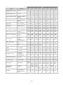
RS-485 Communication
1. DTE supports baudrates 2,400/4,800/9,600/19,200/38,400/57,600/115,200 bps and does not support communication format 7, N, 1/8, E,
2/8, O, 2. Communication protocol = Modbus ASCII or RTU.
2. Function codes: H03 = read maximum 8 words in the register; H06 = write 1 word into the register.
3. Address and contents: Every parameter has 2 communication addresses. One is numbered by the function of the parameter, and the other
is by the order of channel (as shown in the table below).
INA
Content
Explanation
INB
CH1
CH2
CH3
CH4
CH5
CH6
CH7
CH8
Present temperature
value/input error code
Unit; 0.1
See Table 5
H1000
(H1100)
H1001
(H1200)
H1002
(H1300)
H1003
(H1400)
H1004
(H1500)
H1005
(H1600)
H1006
(H1700)
H1007
(H1800)
Set temperature value
Unit: 0.1
H1008
(H1101)
H1009
(H1201)
H100A
(H1301)
H100B
(H1401)
H100C
(H1501)
H100D
(H1601)
H100E
(H1701)
H100F
(H1801)
Max. temperature value
Disabled when higher
than default value
H1010
(H1102)
H1011
(H1202)
H1012
(H1302)
H1013
(H1402)
H1014
(H1502)
H1015
(H1602)
H1016
(H1702)
H1017
(H1802)
Min. temperature value
Disabled when lower
than default value
H1018
(H1103)
H1019
(H1203)
H101A
(H1303)
H101B
(H1403)
H101C
(H1503)
H101D
(H1603)
H101E
(H1703)
H101F
(H1803)
Error temperature value
-999 ~ +999
Unit: 0.1°C
H1020
(H1104)
H1021
(H1204)
H1022
(H1304)
H1023
(H1404)
H1024
(H1504)
H1025
(H1604)
H1026
(H1704)
H1027
(H1804)
Proportional band value
(Pb)
0 ~ 9,999
Unit: 0.1
H1028
(H1105)
H1029
(H1205)
H102A
(H1305)
H102B
(H1405)
H102C
(H1505)
H102D
(H1605)
H102E
(H1705)
H102F
(H1805)
Ti value
0 ~ 9,999
H1030
(H1106)
H1031
(H1206)
H1032
(H1306)
H1033
(H1406)
H1034
(H1506)
H1035
(H1606)
H1036
(H1706)
H1037
(H1806)
Td value
0 ~ 9,999
H1038
(H1107)
H1039
(H1207)
H103A
(H1307)
H103B
(H1407)
H103C
(H1507)
H103D
(H1607)
H103E
(H1707)
H103F
(H1807)
Integration default
0.0 ~ 100.0%
Unit: 0.1%
H1040
(H1108)
H1041
(H1208)
H1042
(H1308)
H1043
(H1408)
H1044
(H1508)
H1045
(H1608)
H1046
(H1708)
H1010
(H1808)
Proportional control offset
error value, when Ti = 0
0.0 ~ 100.0%
Unit: 0.1%
H1048
(H1109)
H1049
(H1209)
H104A
(H1309)
H104B
(H1409)
H104C
(H1509)
H104D
(H1609)
H104E
(H1709)
H104F
(H1809)
Proportional band
coefficient of output 1 and
output 2
0.01 ~ 99.99
Unit: 0.01
H1050
H1051
H1052
H1053
H1054
H1055
H1056
H1057
(H110A) (H120A) (H130A) (H140A) (H150A) (H160A) (H170A) (H180A)
Dead band of control
output 1 & output 2.
-99.9 ~ 999.9
H1058
H1059
H105A
H105B
H105C
H105D
H105E
H105F
(H110B) (H120B) (H130B) (H140B) (H150B) (H160B) (H170B) (H180B)
Hysteresis for output 1
0 ~ 9,999
Unit: 0.1%
H1060
H1061
H1062
H1063
H1064
H1065
H1066
H1067
(H110C) (H120C) (H130C) (H140C) (H150C) (H160C) (H170C) (H180C)
Hysteresis for output 2
0 ~ 9,999
Unit: 0.1%
H1068
H1069
H106A
H106B
H106C
H106D
H106E
H106F
(H110D) (H120D) (H130D) (H140D) (H150D) (H160D) (H170D) (H180D)
-9-
INA
Content
Explanation
CH1
CH2
INB
CH3
CH4
CH5
CH6
CH7
CH8
Read/write output 1 value
Unit: 0.1 %
H1070
H1071
H1072
H1073
H1074
H1075
H1076
H1077
(H110E) (H120E) (H130E) (H140E) (H150E) (H160E) (H170E) (H180E)
Read/write output 2 value
Unit: 0.1 %
H1078
H1079
H107A
(H110F) (H120F) (H130F)
H107B
H107C
H107D
(H140F) (H150F) (H160F)
H107E
H107F
(H170F) (H180F)
Upper limit for alarm output
Alarm enabled when
temperature exceeds
upper limit
H1080
(H1110)
H1081
(1210)
H1082
(H1310)
H1083
(H1410)
H1084
(H1510)
H1085
(H1610)
H1086
(H1710)
H1087
(H1810)
Lower limit for alarm output
Alarm enabled when
temperature falls below
lower limit
H1088
(H1111)
H1089
(H1211)
H108A
(H1311)
H108B
(H1411)
H108C
(H1511)
H108D
(H1611)
H108E
(H1711)
H108F
(H1811)
Tuning for upper limit of
analog output
Current (4 ~ 20mA) or
voltage output tuning
H1090
(H1112)
H1091
(H1212)
H1092
(H1312)
H1093
(H1412)
H1094
(H1512)
H1095
(H1612)
H1096
(H1712)
H1097
(H1812)
Tuning for lower limit of
analog output
Current (4 ~ 20mA) or
voltage output tuning
H1098
(H1113)
H1099
(H1213)
H109A
(H1313)
H109B
(H1413)
H109C
(H1513)
H109D
(H1613)
H109E
(H1713)
H109F
(H1813)
Input sensor type
See “Input” section
H10A0
(H1114)
H10A1
(H1214)
H10A2
(H1314)
H10A3
(H1414)
H10A4
(H1514)
H10A5
(H1614)
H10A6
(H1714)
H10A7
(H1814)
Output function for output 1
0: heating
1: cooling
2: proportional output
H10A8
(H1115)
H10A9
(H1215)
H10AA
(H1315)
H10AB
(H1415)
H10AC
(H1515)
H10AD
(H1615)
H10AE
(H1715)
H10AF
(H1815)
Output function for output 2
0: heating (default)
1: cooling
2: alarm
H10B0
(H1116)
H10B1
(H1216)
H10B2
(H1316)
H10B3
(H1416)
H10B4
(H1516)
H10B5
(H1616)
H10B6
(H1716)
H10B7
(H1816)
Control method
0: PID
1: ON-OFF
2: manual
3: PID programmable
H10B8
(H1117)
H10B9
(H1217)
H10BA
(H1317)
H10BB
(H1417)
H10BC
(H1517)
H10BD
(H1617)
H10BE
(H1717)
H10BF
(H1817)
Alarm 1 output mode
See “Alarm Output”
section
H10C0
(H1118)
H10C1
(H1218)
H10C2
(H1318)
H10C3
(H1418)
H10C4
(H1518)
H10C5
(H1618)
H10C6
(H1718)
H10C7
(H1818)
Alarm 2 output mode
See “Alarm Output”
section
H10C4
(H1518)
H10C5
(H1618)
H10C6
(H1718)
H10C7
(H1818)
Heating/cooling cycle for
output 1
1 ~ 99 seconds
0 = 0.5 second
H10C8
(H1119)
H10C9
(H1219)
H10CA
(H1319)
H10CB
(H1419)
H10CC
(H1519)
H10CD
(H1619)
H10CE
(H1719)
H10CF
(H1819)
Heating/cooling cycle for
output 2
1 ~ 99 seconds
0 = 0.5 second
H10D0
H10D1
H10D2
H10D3
H10D4
H10D5
H10D6
H10D7
(H111A) (H121A) (H131A) (H141A) (H151A) (H161A) (H171A) (H181A)
Run/Stop the control
0: stop
1: executing
2: program stops
3: program pauses
H10D8
H10D9
H10DA H10DB H10DC H10DD H10DE H10DF
(H111B) (H121B) (H131B) (H141B) (H151B) (H161B) (H171B) (H181B)
Status of PID auto-tuning
0: stop
1: executing
H10E0
H10E1
H10E2
H10E3
H10E4
H10E5
H10E6
H10E7
(H111C) (H121C) (H131C) (H141C) (H151C) (H161C) (H171C) (H181C)
Positive/negative
proportional output
0: positive
1: negative (slope)
H10E8
H10E9
H10EA
H10EB H10EC H10ED H10EE
H10EF
(H111D) (H121D) (H131D) (H141D) (H151D) (H161D) (H171D) (H181D)
Other statuses
Other statuses
Communication
specifications
See Table 4
LED status
b1: Alarm 2; b2: °C;
b3:°F; b4: Alarm 1;
b5: OUT2; b6: OUT1;
b7: AT
H10F0
H10F1
Open special
Temperature
function
unit
H10F2
Return to
default
(H1234)
(H1357)
H10F3
H10F4
H10F5
H10F6
H10F7
Reserved
Reserved
Reserved
Reserved
Reserved
H10F9
H10FA
H10FB
H10FC
H10FD
Auto ID
setup
Reserved
Baudrate
ASCII = 0
RTU = 1
8 bits=0
7 bits=1
2 stop=0
1 stop=1
H1124
H1224
H1324
H1424
H1524
H1624
H10F8
- 10 -
H10FE
H10FF
Parity
Address
1 ~ 247
H1724
H1824
Communication Parameter Setting
Content
0
1
2
3
4
5
6
Baudrate
2,400bps
4,800bps
9,600bps
19,200bps
38,400bps
57,600bps
115,200bps
Parity bit
None (N)
Even (E)
Odd (O)
Table 4
Error Codes
The error codes can be read from address H1000 ~ H1007. When the input operation is in normal status, H1000 ~ H1007 are for input values.
When input error occurs (except for stable status and input exceeding the range), DTE will read error codes in H8001 ~ H8002.
H1000
Error description
H8001
EEPROM cannot be written in.
H8002
Input sensor is not connected.
H8003
Group INB is not connected.
Table 5
Analog output current tuning scale: 1μA/scale
Analog output voltage tuning scale: 1mV/scale
Returning to Default Value: Write H1234 into address H10F1 and H1357 into address H10F2. Restart DTE.
Programmable Communication Parameter Setting
INA
Content
Explanation
INB
CH1
CH2
CH3
CH4
CH5
CH6
CH7
CH8
Read remaining time of the step
Unit: sec
H111E
H121E
H131E
H141E
H151E
H161E
H171E
H181E
Read remaining time of the step
Unit: min
H111F
H121F
H131F
H141F
H151F
H161F
H171F
H181F
Read the NO. of the current
pattern
0~7
H1120
H1220
H1320
H1420
H1520
H1620
H1720
H1820
Read the NO. of the current step
0~7
H1121
H1221
H1321
H1421
H1521
H1621
H1721
H1821
NO. of start pattern
0~7
H1122
H1222
H1322
H1422
H1522
H1622
H1722
H1822
NO. of start step
0~7
H1123
H1223
H1323
H1423
H1523
H1623
H1723
H1823
Programmable Parameter Setting
Content
Explanation
Pattern 0 Pattern 1 Pattern 2 Pattern 3 Pattern 4 Pattern 5 Pattern 6 Pattern 7
Max. number of
steps in the pattern
0 ~ 7 = N: The pattern
executes from step 0 to
N.
H2068
H2069
H206A
H206B
H206C
H206D
H206E
H206F
Number of cycles of
pattern 0 ~ 7
execution
0 ~ 199: The pattern has
been executed for 1 ~
200 times
H2070
H2071
H2072
H2073
H2074
H2075
H2076
H2077
NO. of current link
pattern
0 ~ 8: 8 refers to end of
program; 0 ~ 7 refer to
the NO. of next pattern
H2078
H2079
H207A
H207B
H207C
H207D
H207E
H207F
Address
Default
Content
Explanation
2000H ~ 203FH
0
Target temperatures for pattern 0 ~ 7
Pattern 0: 2000H ~ 2007H
Unit: 0.1°C
2080H ~ 20BFH
0
Execution time for pattern 0 ~ 7
Pattern 0: 2080H ~ 2087H
Time: 0 ~ 900 (Unit: 1 min)
4. Communication format: H03 = read bit data; H06 = write bit data
- 11 -
ASCII Mode
Read Command
Read Response Message
Write Command
Write Response Message
Start word
’:’
Start word
’:’
Start word
’:’
Start word
’:’
Machine address 1
‘0’
Machine address 1
‘0’
Machine address 1
‘0’
Machine address 1
‘0’
Machine address 0
‘1’
Machine address 0
‘1’
Machine address 0
‘1’
Machine address 0
‘1’
Command 1
‘0’
Command 1
‘0’
Command 1
‘0’
Command 1
‘0’
Command 0
‘3’
Command 0
‘3’
Command 0
‘6’
Command 0
‘6’
‘1’
Length of response data
(byte)
‘0’
‘1’
‘4’
‘0’
Read start address of
data/bit
‘0’
‘0’
‘0’
‘0’
Read length of data/bit
(word/bit)
‘0’
Data content in H1000
‘0’
‘1’
‘1’
‘0’
‘0’
‘0’
LRC0 check
‘A’
End word 1
CR
End word 0
LF
‘0’
‘0’
‘4’
Data content in H1001
‘0’
Data address
‘1’
‘2’
‘E’
‘0’
‘F’
‘0’
LRC1 check
Data address
‘1’
Write data content
‘3’
‘E’
‘3’
Write data content
‘E’
‘8’
‘8’
‘0’
LRC1 check
‘F’
LRC1 check
‘F’
‘0’
LRC0 check
‘D’
LRC0 check
‘D’
LRC1 check
‘0’
End word 1
CR
End word 1
CR
LRC0 check
‘3’
End word 0
LF
End word 0
LF
End word 1
CR
End word 0
LF
LRC Check
Sum up the contents from “machine address” to “data content”, e.g. H01 + H03 + H10 + H00 + H00 + H02 = H16. Obtain 2’scomplement H
EA.
RTU Mode
Read Command
Read Response Message
Write Command
Write Response Message
Machine address
H01
Machine address
H01
Machine address
H01
Machine address
H01
Command
H03
Command
H03
Command
H06
Command
H06
Read start address of data
H10
H00
H00
Read length of data
(bit/word)
H02
CRC low byte
HC0
CRC high byte
HCB
Length of response data
(byte)
Data content 1
Data content 2
H04
H01
HF4
Write data address
Write data content
H01
H03
H20
Write data address
Write data content
H10
H01
H03
H20
H03
CRC low byte
HDD
CRC low byte
HDD
H20
CRC high byte
HE2
CRC high byte
HE2
CRC low byte
HBB
CRC high byte
H15
CRC (Cyclical Redundancy Check) is obtained by the following steps:
unsigned int reg_crc = 0xffff;
i = 0;
while (length--)
{ reg_crc ^= RTUData[i];
i ++;
for (j = 0; j < 8; j++)
{ if (reg_crc & 0x01)
else
}
}
return(reg_crc);
H10
reg_crc = (reg_crc >> 1) ^ 0xA001;
reg_crc = reg_crc >> 1;
Software for Setting up Communication on PC: Download the free software on Delta’s website.
- 12 -
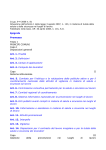
How to Mount & DIN Rail Size
Connect maximum 7 DTC2000 or DTC2001 controllers to DTE by using DIN rail.
- 13 -