1
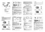
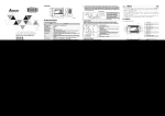
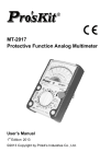
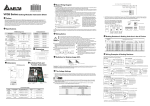
] Wiring Warnings 3.2 Brake unit 2008-09-10 5011669601-1CBU VFDB 4132 Series Brake Modules CHARGE ACT OC OH VFDB4132 Instruction Sheet X Preface Thank you for choosing DELTA’s brake module. VFDB brake units are applied to absorb the motor regeneration energy when the three-phase induction motor stops by deceleration. With VFDB brake unit, the regeneration energy will be dissipated in dedicated brake resistors. To prevent mechanical or human injury, please refer to this instruction sheet before wiring. VFDB brake units are suitable for DELTA AC Motor Drives VFD Series 230V/460V/575V. VFDB brake units need to be used in conjunction with BR series brake resistors to provide the optimum brake characteristics. VFDB brake units (4132) are approved by Underwriters Laboratories, Inc. (UL) and Canadian Underwriters Laboratories (cUL). The content of this instruction sheet may be revised without prior notice. Please consult our distributors or download the most updated version at http://www.delta.com.tw/industrialautomation. [ Internal Components and Terminals 4.1 Internal Components VFDB series VFD series AC Motor Drive Max 8M Brake Unit BR S S B1 B2 BR B2 BR O.L. B1 B2 BR O.L. The Position of the Jumper MASTER/SLAVE Setting Jumper S Input Voltage Setting 480V 460V 440V 415V 400V 380V M1 M2 S1 S2 SLAVE output/input terminal M1: SLAVE output signal + M2: SLAVE output signal S1: SLAVE input signal + S2: SLAVE input signal NOTE: Please use shielded wires while wiring. RA RC Alarm output terminals NOTE Wire Gauge AWG (mm2) 4~6AWG Power Input DC+, DC(13.3~21.2mm2) Circuit 4~6AWG Brake B1, B2 Resistor (13.3~21.2mm2) Output M1, M2 18~20AWG SLAVE (0.8~0.5mm2) Circuit Input S1, S2 (With shielded wires) 18~20AWG Fault RA, RC Circuit (0.8~0.5mm2) Circuit 75 618/642/667/690/725/750±6V Protection Environment Terminals Screw Torque NFB MC R/L1 S/L2 T/L3 O.L. MC SA Surge Absorber Thermal O verload Relay or Tem perature switch R/L1 S/L2 T/L3 R/L1 S/L2 T/L3 VFD Series +(P) -(N) E.F DCM The definition of the brake usage ED(%) is to assure having enough time for the brake unit and brake resistor to dissipate the heat generated by brake. When the brake resistor heats up, the resistance would increase with temperature, and brake torque would decrease accordingly. M2 4 kgf-cm (3 in-lbf) _ The Voltage Settings M2 4 kgf-cm (3 in-lbf) 1. Voltage setting: the power source of the brake unit is DC voltage from +(P), -(N) M8 terminals of the AC motor drive. It is very important to set the voltage of the brake unit based on the actual input power of the AC motor drive before operation. The setting has a great influence on the potential of the operation voltage for the brake unit. Please refer to the table below. NOTE Motor IM DC+ B1 DC- VFDB RA Brake Unit B2 RC Therm al Overload Relay 3.1 Brake resistor O.L. BR Brake Resistor Please make sure that power is OFF before setting the jumper. The steps for jumper setting: Step 1. Remove the top cover. Step 2. Remove the screws on the side case (3 screws for each side). Step 3. Remove the screws that connected bottom case to the side case (2 screws for each side). Step 4. After removing the power line of the fan, pull out the heat sink slowly until the jumper can be seen. Then the jumper can be set. For safety consideration, install an overload relay between the brake unit and the brake resistor. In conjunction with the magnetic contactor (MC) prior to the drive, it can perform complete protection against abnormality. The purpose of installing the thermal overload relay is to protect the brake resistor from damage due to frequent brake, or due to brake unit keeping operating resulted from unusual high input voltage. Under such circumstance, just turn off the power to prevent damaging the brake resistor. Please refer to the specification of the thermal overload relay. The alarm output terminals (RA, RC) of the brake unit will be activated when the temperature of the heat sink exceeds 95°C. It means that the temperature of the installation environment may exceed 50°C, or the brake %ED may exceed 10%ED. With this kind of alarm, please install a fan to force air-cooling or reduce the environment temperature. If the condition not due to the temperature, the control circuit or the temperature sensor may have been damaged. At this time, please send the brake unit back to the manufacturer or agency for repair. The AC Motor Drive and brake unit will be electrified at the same time while turning on the NFB (No-fuse breaker). For the operation/stop method of the motor, please refer to the user manual of the AC Motor Drives VFD Series. The brake unit will detect the inner DC voltage of the AC motor drive when it stops the motor by deceleration. The extra regeneration will be dissipated away rapidly by the brake resistor in the form of heat. It can ensure the stable deceleration characteristic. Besides, using thermal overload relay to be the protection system and brake resistor, temperature switch can be installed on brake resistor side as the protection. The temperature switch must comply with the brake resistor specification or contact your dealer. AC Motor Drives Series Before changing the setting of the power voltage, make sure the power has been turned off. Please set power voltage as the possible highest voltage for unstable power system. Take 380VAC power system for example. If the voltage may be up to 410VAC, 415VAC should be set. For DELTA’s AC motor drive (VFD Series), please set parameter (Over Voltage Stall Prevention) as “close” to disable over-voltage stall prevention, to ensure stable deceleration characteristic. Table 1: The Selection of AC Power Voltage and Voltage Setting Brake Start-up voltage DC Bus (DC+, DC-) Voltage 618VDC 642VDC 667VDC 690VDC 725VDC 750VDC NOTE: Input Power With Tolerance ±10% AC Power Voltage 380VAC (460V Mode) 400VAC (460V Mode) 415VAC (460V Mode) 440VAC (460V Mode) 460VAC (460V Mode) 480VAC (460V Mode) Input voltage setting for VFDB 4132 CHARGE ACT Input Voltage Setting OC OH Power lamp Brake lamp Over-current Overheat lamp lamp 480V 460V For VFDB 4132 Factory setting: 440V 440V 415V 400V 380V 2. MASTER (M) /SLAVE (S) setting: the factory setting is “M”. The “S” setting is applied to two or more brake units in parallel, making these brake units be enabled/disabled synchronously. Then the power dissipation of each unit will be equivalent so that they can perform the brake function completely. In the following diagram, it shows jumper setting for the application of three brake units. After wiring, the jumper in the first brake unit should be set to “M” and others must be set to “S” to complete the system setting. Min. Typical Applicable Resistor Value Brake Unit Full-load Brake Resistors Brake Thermal Equivalent Motor Spec. for Each Part No. Torque Torque Resistor Value Overload Part No. and AC Motor and Relay kg-M Quantity 10%ED for Each AC HP kW Drive Quantity Value Motor Drive 120 90 52.5 13500W 5Ω 4132 1 BR1K5W005 9 120 5Ω 110A 150 110 61 21600W 4Ω 4132 1 BR1K2W008 18 120 4Ω 135A 175 132 73.5 21600W 4Ω 4132 1 BR1K2W008 18 100 4Ω 135A 215 160 89 21600W 3.4Ω 4132 1 BR1K2W6P8 18 97 3.4Ω 160A 250 185 103 27000W 2.5Ω 4132 2 BR1K5W005 18 115 2.5Ω 220A 300 220 122.5 27000W 2.5Ω 4132 2 BR1K5W005 18 96 2.5Ω 220A a Examples NOTE Tem perature Sw itch NOTE ED% = T1/T0x100(%) T0 30 kgf-cm (26 in-lbf) 30 kgf-cm (26 in-lbf) M8 Note 1: When the AC m otor drive is used with DC reactor, please refer to the wiring diagram in the AC drive user manual for wiring terminal DC+ of br ake unit. Note 2: DO NOT wire terminal D C- to the neutral point of power system. T1 Cycle Time \ Basic Wiring Diagram Brake Resistors Specification 1500W 5.0Ω 1200W 6.8Ω 1200W 8.0Ω 1500W 40Ω 1000W 50Ω 1000W 75Ω Brake Time Voltage 4.2 Wire Gauge for Terminals 240 Input DC Voltage 480-750VDC Rating 3.4Ω Min. Equivalent Resistor for Each Brake Unit Heat Sink Overheat Temperature Temperature exceeds +95 oC (203oF) Relay contact 3A250VAC/30VDC Alarm Output for Overheat (RA, RC) ON until the bus (P-N) voltage is Power Charge Display below 50VDC Over-current Protection Level 320A Indoor (no corrosive gases, metallic Installation Location dust) Operating Temperature -10oC~+50oC (14oF to 122oF) Storage Temperature -20oC ~+60oC (-4oF to 140oF) Humidity Less than 90% Non-condensing 9.8m/s2 (1G) under 20Hz / 2m/s2 Vibration (0.2G) at 20~50Hz Mechanical Configuration Wall-mounted enclosed type IP10 Z Dimensions S1 S2 M M 460V Output Rating Braking Start-up Voltage (DC) DC+ DC - M1 M2 S1 S2 ` Brake Resistors/Units for Delta VFD 460V Series 132 Continuous Discharge Current (A) DC+ DC - M1 M2 O.L. Max 5M Brake Resistor VFDB 4132 Brake Units Max. Discharge Current (A) 10%ED DC+ DC - B1 100% Specification Max. Motor Capacity (kW) -(N) VFD Series ^ Definition for the Brake Usage ED% Y Specifications Model no. BR1K5W005 BR1K2W6P8 BR1K2W008 BR1K5W040 BR1K0W050 BR1K0W075 +(P) Do not proceed with wiring while power is applied to the circuit. The wiring gauge and distance must comply with the local regulations. The +(P), -(N) terminals of the AC motor drive (VFD Series), connected to the brake unit (VFDB), must be confirmed for correct polarity lest the drive and the brake unit be damaged when power on. When the brake unit performs braking, the wires connected to DC+, DC-, B1 and B2 would generate a powerful electromagnetic field for a moment due to high current passing through. These wires should be wired separately from other low voltage control circuits lest they make interference or mis-operation. Inflammable solids, gases or liquids must be avoided at the location where the brake resistor is installed. The brake resistor had better be installed in individual metallic box with forced air-cooling. Connect the ground terminal to the Earth Ground. The ground lead must be at least the same gauge wire as leads DC+, DC-. Please install the brake resistor with forced air-cooling or the equivalent when frequent deceleration braking is performed (over 10%ED). Do NOT change any wirings and settings and touch any terminals and components while power is applied to avoid electric shock. It is recommended to use the ring terminals for main circuit wiring. Make sure the terminals are fastened before power on. Wiring distance Before wiring, please notice equivalent resistors value shown in the column “Equivalent resistors specification for each brake unit” in the above table to prevent damage. 460V 120HP B1 VFD Series +(P) DC+ -( N) DC- O.L. VFDB 4132 Bra ke Uni t BR BR BR BR BR BR BR BR Bra ke Resisto r BR M VFD900_43_ Thermal O ver loa d Rel ay B2 VFD9 00_43 _ uses wi th 3 BR sets in pa rall el, which 3P CS 1K 5W00 5 brake r esistors ar e co nnected in ser ies. 460V 150HP, 175HP, 215HP T herm al Ov er load Rel ay + (P) VF D Ser ies -( N) VF D1100_ 43_ VF D13 20_43_ VF D16 00_43_ D C+ B1 O.L. VF DB D C4132 Bra ke U nit M BR BR BR BR BR BR Bra ke BR BR BR BR BR BR R esi stor BR BR BR BR BR BR B2 VF D1100_ 43_ us es w it h 6 BR s ets in p aral lel, w hic h 3PC S 1K2W 008 bra ke r es is to rs are c on nec te d in s erie s. VF D13 20_43_ use s w ith 6 BR s ets in par all el, wh ic h 3PCS 1 K2W00 8 brak e res is tors are c on nec te d in s erie s. VF D16 00_43_ use s w it h 6 BR sets in pa rall el, wh ic h 3PC S 1K2W6 P8 brak e re si stor s are c on nec te d in s erie s. 460V 250HP, 300HP Thermal O verload Rel ay + (P) -( N) VF D Ser ies VFD1850_43_ VFD2200_43_ DC+ DC- B1 VFDB O.L . 4132 Brak e Unit M B2 M1 M2 Thermal O verload Rel ay DC+ DC- B1 BR BR BR VFDB O.L . Brak e 4132 BR BR BR Resis tor BR BR BR Brak e Unit BR BR BR BR BR BR BR BR BR Brak e Resis tor S B2 S1 S2 VFD1850_43_ uses with 2 VF DB4132 brak e units and each brake unit us es with 3 BR sets i n parall el, which 3PCS 1K5W005 brak e resis tors are connec ted in series. VFD2200_43_ uses with 2 VF DB4132 brak e units and each brake unit us es with 3 BR sets i n parall el, which 3PCS1K5W005 brake resi stors are c onnect ed in s eri es . ]੨ቢڦຍְี 3.2 VFDB 4132 制動單元 VFDB4132 րЕ֘ሀ CHARGE ACT OC 制動單元在執行煞車時,DC+、DC-、B1、B2 因有大電流通過所連接的導線瞬間 將產生能量很大的電磁場;故在初期配線施工規劃時,應與其它低電壓的控制線路 分離配線,以免造成不必要的干擾或誤動作。 OH X݈֏ 主動從動 設定插梢 制動單元的接地工程 230V 級請依第三種接地施工,460V 級請依特別第三種接地 施工。 在減速煞車頻繁的場合(超過 10%ED)煞車電阻請加裝風扇強制風冷或其它冷卻 設備。 所有的主回路端子請使用 O 型端子配線,並確認端子已鎖緊方可送電運行。 配線距離 VFD 系列 交流馬達驅動器 VFDB 4132 制動單元規格 回路名稱 制 動 時間 導線線徑 AWG (mm2) 4~6AWG (13.3~21.2mm2) 端子記號 電源輸入 回路 煞車電阻 回路 DC+, DCB1, B2 輸出 M1, M2 連動回路 輸入 S1, S2 RA, RC 故障回路 4~6AWG (13.3~21.2mm2) 18~20AWG (0.8~0.5mm2) (需用隔離線) 18~20AWG (0.8~0.5mm2) M8 30 kgf-cm (26 in-lbf) M8 30 kgf-cm (26 in-lbf) M2 4 kgf-cm (3 in-lbf) M2 4 kgf-cm (3 in-lbf) 480V 460V 440V 415V 400V 380V _ నؠᄃአፋ 1. NFB R/L1 S/L2 T/L3 O.L. MC SA 突波吸收器 積熱電驛或溫度開關跳脫接點 Ż͎ R/L1 S/L2 T/L3 R/L1 S/L2 T/L3 VFD Series +(P) -(N) E.F DCM Motor IM 積熱電驛 DC+ B1 DC- VFDB RA 制動單元 RC O.L. BR 煞車電阻 B2 NOTE 制動開始電壓 DC+、DC母線 DC 電壓 618Vdc 642Vdc 667Vdc 690Vdc 725Vdc 750Vdc 註:容許輸入電源有±10%的變動 VFDB 4132 設定位置 加裝積熱電驛的主要目的是為了保護煞車電阻不因煞車頻繁過熱而燒毀,或是因輸 入電源電壓異常過高導致制動單元連續導通燒毀煞車電阻。此時只有將交流馬達驅 動器的電源關閉才可避免煞車電阻燒毀。 電源燈 積熱電驛規格的選用請參考制動單元與放電電阻適用一覽表。 制動單元中的故障輸出端子(RA、RC)在散熱裝置溫度高於 95℃時會動作,表 示安裝環境溫度可能超過 50℃以上,或是煞車制動 ED%超過 10%ED;若是此類 的故障請自行加裝風扇強制風冷或改善環境溫度。若非溫度原因,可能控制電路受 損或溫度感測器故障,此時請送廠維修。 使用本公司 VFD 系列交流馬達驅動器,請將參數的過電壓失速防止功能設定為關 閉狀態,使失速防止功能失效,如此可得穩定的減速特性。 在安裝制動單元的應用中為了安全的考量,在制動單元與煞車電阻之間加裝一積熱 電驛(O.L) ;並與交流馬達驅動器前端的電磁接觸器(MC)作一連鎖的異常保護。 設定電源電壓時,請務必先將電源關閉後才可更改設定值。若在電源電壓不穩定的 區域,請將電源電壓設定在可能出現的最高電壓。例如:380Vac 的電源系統,若 電壓變動達到 410Vac,請設定在 415Vac。 380Vac(460V Mode) 400Vac(460V Mode) 415Vac(460V Mode) 440Vac(460V Mode) 460Vac(460V Mode) 480Vac(460V Mode) 請勿將電源輸入迴路DC-端,接至電力系統之中性點。 本配線電路在電源開關(NFB)開啟時交流馬達驅動器與制動單元便同時通上電 源,馬達的運轉/停止的方式請參考 VFD 系列的使用手冊;制動單元會在交流馬 達驅動器對馬達作減速煞車時自動偵測交流馬達驅動器內部的直流電壓,自動將過 多的回生能量藉由煞車電阻以熱能的方式迅速消耗以達平穩的減速特性。 除了使用積熱電驛作為保護系統及制動電阻外,尚可加裝溫度開關於制動電阻端作 為保護。溫度開關的動作溫度需配合制動電阻規格,或洽詢經銷商詢問。 CHARGE ACT 煞車燈 OC OH 過流燈 過熱燈 輸入電源電壓設定 VFDB4132 系列 請依右邊文字設定 出廠設定值為440V 2. BR O.L. B2 BR O.L. RA RC 故障輸出端子 M1: 連動信號輸出 + 端 M2: 連動信號輸出 - 端 S1: 連動信號輸入 + 端 S2: 連動信號輸入 - 端 注意:請使用隔離線配線施工 必須在關電的狀態下,才能切換插梢位置。 切換插梢位置動作順序:卸下上蓋,然後卸下外殼兩旁螺絲共六顆(左右各三顆), 再卸下風扇組與外殼間的螺絲共四顆(左右各二顆)。此時,須拔除風扇組的電源 線後,將散熱片緩慢抽出至露出插梢即可,然後切換插梢位置。 適用馬達 HP kW 120 90 全載輸 每台交流馬達 出轉矩 驅動器等效煞 制動單元 車電阻規格 kg-M 每台交流 積熱電 制動 驛 馬達驅動 轉矩 器等效最 規格中 10%ED 小電阻值 心值 制動電阻料號 52.5 13500W 5Ω 4132 1 BR1K5W005 9 120 5Ω 110A 150 110 61 21600W 4Ω 4132 1 BR1K2W008 18 120 4Ω 135A 175 132 73.5 21600W 4Ω 4132 1 BR1K2W008 18 100 4Ω 135A 215 160 89 21600W 3.4Ω 4132 1 BR1K2W6P8 18 97 3.4Ω 160A 250 185 103 27000W 2.5Ω 4132 2 BR1K5W005 18 115 2.5Ω 220A 300 220 122.5 27000W 2.5Ω 4132 2 BR1K5W005 18 96 2.5Ω 220A a טજܡ੨ቢဦּ NOTE 在配線前,注意:每台煞車模組之等效煞車電阻不能低於每台制動單元最小等效電 阻值(參閱制動單元與放電電阻適用一覽表)。 460V 120HP AC 電源電壓 溫度開關 M1 M2 S1 S2 連動輸出/輸入端子 480V 460V 440V 415V 400V 380V + (P) D C+ -( N) D C- VFD系列 VFD900_43_ 如下圖所示為三台制動單元連動制動的應用;當配線完成後需將第一台設為“M" 主動的設定,其餘的一定要將插梢設定在“S"連動的位置上,如此即可完成動力 制動系統的配線。 O.L. VF DB 4132 制動 單元 M BR BR BR BR BR BR BR BR BR 煞車 電阻 B2 VF D9 00_4 3_ 使 用B R1K 5W0 05 9P CS , 每3P CS 串 聯 後 再 並 聯 接 線 460V 150HP, 175HP, 215HP 積熱 電驛 VF D系 列 + (P) D C+ -( N) D C- VF D1100_ 43_ VF D1 320_43 _ VF D1 600_43 _ B1 O.L. VF DB 4132 制動 單元 M 煞車 電阻 BR BR BR BR BR BR BR BR BR BR BR BR BR BR BR BR BR BR B2 VF D1100_ 43_ 使 用1 K2W00 8 18P CS , 每 3PC S串 聯 後 再 並 聯 接 線 VF D1 320_43 _使 用1K2W 008 18PC S , 每3 PCS 串 聯 後 再 並 聯 接 線 VF D1 600_43 _使 用1K2W 6P8 18PC S , 每3 PCS 串 聯 後 再 並 聯 接 線 460V 250HP, 300HP +( P) -( N) VF D系 列 主動(M)/連動(S)的設定:制動單元在出廠時均設定在“M"主動煞車的位 置。“S"連動位置的功能主要是應用於兩台以上制動單元。 積熱 電驛 B1 表一:電源電壓的選擇與 PN 直流電壓的動作準位 當交流馬達驅動器有加裝直流電抗器(DC Reator)時,其煞車模組之電 源輸入迴路DC+端的配線方法,可參考交流馬達驅動器手冊。 3.1 煞車電阻 電源電壓的調整:制動單元的電力來源是接受接交流馬達驅動器+ (P)、 - (N)兩端 供應的直流電源。因此,在配線完成準備運轉時,依交流馬達驅動器的實際輸入 電源來設定制動單元的電源電壓是非常重要的步驟;此設定將會影響制動單元動 作電壓的位準,下表為各個電壓動作準位。 NOTE MC B1 B2 NOTE 使 用 率ED%=T1/T0x100(% ) 制定煞車使用率 ED%,主要是為了能讓制動單元及煞車電阻有充份的時間來散除因制 動而產生的熱量;當煞車電阻發熱時,電阻值將會隨溫度的上昇而變高,制動轉矩亦隨 之減少。 \ૄώ੨ቢဦ 規格 1500W 5.0Ω 1200W 6.8Ω 1200W 8.0Ω 1500W 40Ω 1000W 50Ω 1000W 75Ω T0 BR S 輸入電壓設定 T1 週期 時 間 扭力 螺絲規格 B1 B2 ` טજಏ̮ᄃٸܡዋϡ˘ᜓܑ 連動 故障 回路 輸出 端子 端子 4.1 各端子使用線徑 S 插梢位置 主動/連動設定端子 M 電壓 電源輸入端子 煞車電阻端子 DC+ , D CB1, B2 S1 S2 M1 M2 VFDB 4132 設定位置 Max 5M 煞車電阻 制動單元 DC+ DC - S1 S2 S O.L. 100% 240 煞車電阻 Max 8M BR ^ ֹ֘ϡத ED%۞ؠཌྷ 460V 系列 132 75 618/642/667/690/725/750±6V 480-750VDC 3.4Ω 溫度超過 +95℃ (203oF) RELAY 接點 3A250Vac/30Vdc(RA.RC) 主回路 (P-N) 電壓在 50VDC 以下熄滅 320A 屋內(無腐蝕性氣體、金屬粉塵) -10℃~+50℃ (14oF to 122oF) -20℃~+60℃ (-4oF to 140oF) 90%RH 以下不結露 20Hz 以下 9.8m/S2(1G)、20~50Hz 2m/S2(0.2G) 壁掛型 IP10 VFDB 系列 DC+ DC - M B1 在通電中嚴禁修改任何配線及制動單元內部設定,更嚴禁在通電中碰觸相關配線的 端子及 PCB 板中的任一元件,以免因通電中遭極度危險的直流高壓感電造成人員 傷害。 輸入電源 電壓設定 插梢 Yఢॾ M1 M2 煞車電阻安裝的場所不能有任何易燃性的物體、氣體、液體,最好能安裝在獨立的 金屬箱內並加以風扇散熱。 [ЧొЩჍ̈́Αਕᄲځ DC+ DC - VFD Series 460V 感謝您選用台達 VFDB 動力制動煞車模組。本產品主要應用於當三相感應馬達由 交流馬達驅動器所驅動,在減速停止時用以吸收由馬達側所回生的能量。藉由 VFDB 制動單元將此能量以熱能的方式消耗在煞車電阻上。本產品在安裝使用前, 請詳細參閱本說明書再進行施工配線,以免造成機械或人員的傷害。VFDB 動力制 動煞車模組適用於本公司 VFD 所有系列的交流馬達驅動器。VFDB 制動單元需搭 配煞車電阻 BR 系列,才能發揮優異的制動特性,詳細的規格及使用方法請繼續參 閱本說明書。由於產品精益求精,當內容規格有所修正時,請洽詢代理商或至台達 網站(http://www.delta.com.tw/industrialautomation/)下載最新版本。 型號 BR1K5W005 BR1K2W6P8 BR1K2W008 BR1K5W040 BR1K0W050 BR1K0W075 交流馬達驅動器(VFD)連接至制動單元(VFDB)的 DC+、DC- 端子有極性之 分,千萬要確認再確認,否則電源一開啟制動單元立即炸毀,請務必注意。 VFDB4132 ᄲځ३ 使用電壓等級 最大適用馬達容量 (kW) 最大放電電流(A peak) 輸出 10%ED 連續放電電流 (A) 額定 制動起始電壓 (DC) 電源 直流電壓 每台等效最小電阻 散熱片過熱溫度 過熱故障輸出 保護 充電中顯示 過電流 OC 保護準位 安裝場所 環境溫度 使用 儲存溫度 環境 濕度 振動 機構構造 -(N) +( P) 進行配線施工時務必確認相關回路電源均為關閉狀態;配線的線徑及距離亦務必按 照規定選用及施工。 VFD1850_43_ VFD2200_43_ DC+ DC- 積 熱電 驛 積 熱電 驛 B1 VFDB 4132 制 動單 元 M B2 M1 M2 DC+ DC- B1 BR BR BR BR BR BR VFDB O.L . O.L . 4132 BR BR BR BR BR BR 制 動單 元 BR BR BR BR BR BR 煞 車電 阻 S B2 S1 S2 VFD1850_43_使 用2台 VF DB4132制動 單元, 每 台使 用BR1K5W005 9PCS, 每3PCS 串 聯後 再並 聯接 線 VFD2200_43_使 用2台 VF DB4132制動 單元, 每 台使 用BR1K5W005 9PCS, 每3PCS 串 聯後 再並 聯接 線 煞 車電 阻