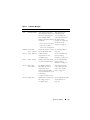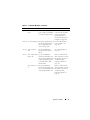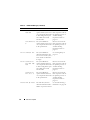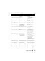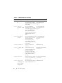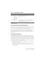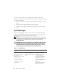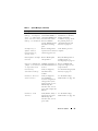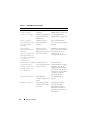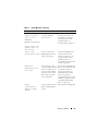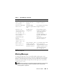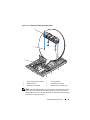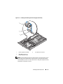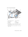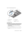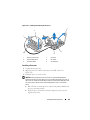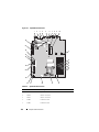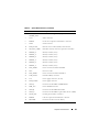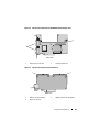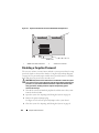
1
3
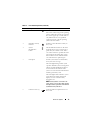
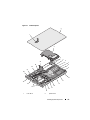
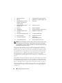
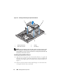
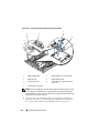
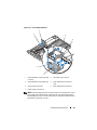
system board shroud
4
redundant power supplies (optional)
5
left riser
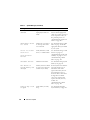
6
SAS external controller daughter card
7
SAS RAID external controller
daughter card battery and
memory module
8
center riser
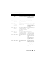
9
SAS internal RAID controller
daughter card
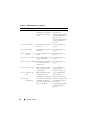
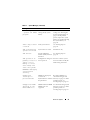
10
SAS card connector
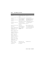
11
RAC card
12
memory modules (6)
13
CPU/heatsink
14
dual fan module bays 1 and 2 (4 fans)
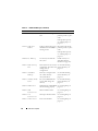
15
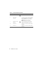
SAS/SATA backplane cable
connector
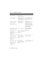
16
SATA/SAS backplane cable
17
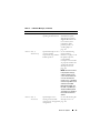
hot plug hard drive bays 0 and 1
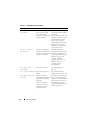
18
one optional slimline drive
19
LCD control panel
20
chassis intrusion switch
21
control panel assembly
22
power supply
dual fan modules (2 fans)
23
power distribution board
24
power distribution board cover
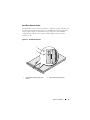
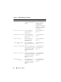
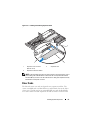
NOTE: In the preceding figure, the 12C cable is shown connecting over the control
panel cabling. This cable should be routed under the control panel cable and the
internal USB key connector. The 12C cable seats in a cable guide clip that is directly
beneath the control panel connector.
The system board holds the system's control circuitry and other electronic
components. The processor and memory are installed directly on the system
board. Using a riser card, the system can accommodate two expansion cards.
The peripheral bays provide space for up to two hard drives and an optional
optical drive. Power is supplied to the system board and drives through one
nonredundant power supply. The optical drive connects to the SATA
controller on the system board. For more information, see "Optical Drive" on
page 79.
The hard-drive bays provide space for up to two 3.5-inch SAS or two 3.5-inch
SATA hard drives. The hard drives connect to a SAS controller card through
the SAS/SATA backplane board. For more information, see "Hard Drives" on
page 73, "Backplane Board" on page 100, and "Expansion Cards" on page 95.
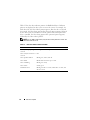
During an installation or troubleshooting procedure, you may be required to
change a jumper setting. For more information, see "System Board Jumpers"
on page 155.
66
Installing System Components