1
2
Access Gateway mapping
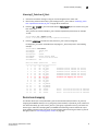
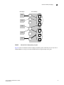
• When configuring secondary port mapping for failover and failback situations, make sure that
initiator and target F_Ports will not fail over or fail back to the same N_Port.
Brocade 8000 mapping differences
The Brocade 8000 contains 24 internal FCoE ports and eight external Fibre Channel ports. In
Access Gateway mode, the internal FCoE ports are configured logically as F_Ports, while the
external Fibre Channel ports are configured as N_Ports. The FCoE ports are divided into six groups
or trunks consisting of four ports each. All four ports in a group are mapped to one N_Port.
Although you can change the default port mapping for these groups (refer to “Default port
mapping” on page 12), consider the following when working with these FCoE ports:
• All four FCoE ports in the group are mapped to the same N_Port.
• You cannot map individual FCoE ports within the same port group to different N_Ports.
• Any Access Gateway operation that involves moving F_Ports will move all FCoE ports in the
group.
• All four FCoE ports in a group will failover or failback to one N_Port.
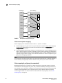
Default port mapping
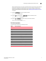
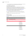
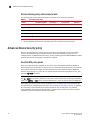
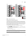
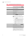
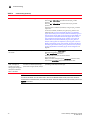
Table 5 shows the default port mapping. By default, Failover and Failback policies are enabled on
all N_Ports.
NOTE
All POD licenses must be present to use Access Gateway on the Brocade 5100 and 300.
TABLE 5
.
12
Access Gateway default port mapping
Brocade
Model
Total Ports
F_Ports
N_Ports
Default Port Mapping
VA40-FC
40
0-31
32-39
0-3 mapped to 32
4-7 mapped to 33
8-11 mapped to 34
12-15 mapped to 35
16-19 mapped to 36
20-23 mapped to 37
24-27 mapped to 38
28-31 mapped to 39
300
24
0-15
16 -23
0, 1 mapped to 16
2, 3 mapped to 17
4, 5 mapped to 18
6, 7 mapped to 19
8, 9 mapped to 20
10, 11 mapped to 21
12, 13 mapped to 22
14, 15mapped to 23
Access Gateway Administrator’s Guide
53-1001760-01