1
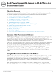
Dell PowerConnect
W-AirWave 7.6
Getting Started Guide
Copyright
© 2013 Aruba Networks, Inc. Aruba Networks trademarks include
, Aruba Networks®, Aruba Wire®
less Networks , the registered Aruba the Mobile Edge Company logo, and Aruba Mobility Management System®.
Dell™, the DELL™ logo, and PowerConnect™ are trademarks of Dell Inc.
All rights reserved. Specifications in this manual are subject to change without notice.
Originated in the USA. All other trademarks are the property of their respective owners.
Open Source Code
Certain Aruba products include Open Source software code developed by third parties, including software code
subject to the GNU General Public License (GPL), GNU Lesser General Public License (LGPL), or other Open
Source Licenses. Includes software from Litech Systems Design. The IF-MAP client library copyright 2011
Infoblox, Inc. All rights reserved. This product includes software developed by Lars Fenneberg, et al. The Open
Source code used can be found at this site:
http://www.arubanetworks.com/open_source
Legal Notice
The use of Aruba Networks, Inc. switching platforms and software, by all individuals or corporations, to terminate
other vendors’ VPN client devices constitutes complete acceptance of liability by that individual or corporation for
this action and indemnifies, in full, Aruba Networks, Inc. from any and all legal actions that might be taken against it
with respect to infringement of copyright on behalf of those vendors.
Jan 2013 | 0511224-01
Dell PowerConnect W-AirWave 7.6 | Getting Started Guide
Chapter 1
Overview
Congratulations on successfully installing Dell PowerConnect W-AirWave! So where do you go from here? This
document is designed to help you with your initial setup. It also provides information on common configuration
options and daily monitoring practices.
Refer to the following sections:
l
"Initial Setup" on page 1
l
"Common Configuration Options" on page 11
l
"Monitoring Practices" on page 23
Initial Setup
AirWave initial setup consists of creating folders and groups, discovering and adding devices, and defining credentials
for devices that communicate with AirWave. Refer to the following sections for additional information.
l
"How do I add devices?" on page 1
l
"How do I discover new devices?" on page 7
l
"How are folders and groups organized?" on page 6
l
"How do I define credentials for devices that communicate with AirWave?" on page 9
How do I add devices?
In many cases, you will add devices after the devices have been discovered. Refer to "How do I discover new
devices?" on page 7 for more information. In other cases, your deployment may require that you manually add
devices to AirWave. You can add devices manually by uploading a CSV file or from the Device Setup > Add page.
NOTE: Dell PowerConnect W-Instant devices are automatically discovered. Refer to the Dell PowerConnect W-Instant in W-AirWave
7.6 Deployment Guide for more information on Dell PowerConnect W-Instant devices in AirWave.
Refer to the following sections for information on manually adding devices.
l
"Adding Devices with the Device Setup > Add Page" on page 1
l
"Adding Multiple Devices from a CSV File" on page 4
l
"Adding Universal Devices" on page 5
Adding Devices with the Device Setup > Add Page
Manually adding devices from the Device Setup > Add page to AirWave is an option for adding all device types.
You only need to select device vendor information from the drop down menu, and AirWave automatically finds and
adds specific make and model information into its database.
Perform these steps to manually add devices to AirWave:
Dell PowerConnect W-AirWave 7.6 | Getting Started Guide
Overview | 1
1. The first step to add a device manually is to select the vendor and model. Browse to the Device Setup > Add
page and select the vendor and model of the device to add. Figure 1 illustrates this page.
Figure 1: Device Setup > Add Page Illustration
2. Select Add. The Device Communications and Location sections appear, illustrated in Figure 2.
2 | Overview
Dell PowerConnect W-AirWave 7.6 | Getting Started Guide
Figure 2: Device Setup > Add > Device Communications and Location Sections
3. Complete the Device Communications and Location settings for the new device. Settings can differ from device
to device based on the type of device and the features that the device supports. In several cases, the default
values from any given device derive from the Device Setup > Communication page.
4. In the Location field, select the appropriate group and folder for the device.
5. At the bottom of the page, select either the Monitor Only or Management read/write radio button. The choice
depends on whether or not you want to overwrite the Group settings for the device being added.
NOTE: If you select Manage read/write, AirWave overwrites existing device settings with the Groups settings. Place newly discovered
devices in Monitor read/only mode to enable auditing of actual settings instead of Group Policy settings.
6. Select Add to finish adding the devices to the network.
Dell PowerConnect W-AirWave 7.6 | Getting Started Guide
Overview | 3
Adding Multiple Devices from a CSV File
You can add devices in bulk from a CSV file to AirWave. Here you also have the option of specifying vendor name
only, and AirWave will automatically determine the correct type while bringing up the device. If your CSV file
includes make and model information, AirWave will add the information provided in the CSV file as it did before. It
will not override what you have specified in this file in any way.
The CSV list must contain the following columns:
l
IP Address
l
SNMP Community String
l
Name
l
Type
l
Auth Password
l
SNMPv3 Auth Protocol
l
Privacy Password
l
SNMPv3 Privacy Protocol
l
SNMPv3 Username
l
Telnet Username
l
Telnet Password
l
Enable Password
l
SNMP Port
You can download a CSV file and customize it as you like.
1. To import a CSV file, go to the Device Setup > Add page.
2. Select the Import Devices via CSV link. The Upload a list of devices page displays. See Figure 3.
4 | Overview
Dell PowerConnect W-AirWave 7.6 | Getting Started Guide
Figure 3: Device Setup > Add > Import Devices via CSV Page Illustration
3. Select a group and folder into which to import the list of devices.
4. Select Choose File and select the CSV list file on your computer.
5. Select Upload to add the list of devices into AirWave.
Adding Universal Devices
AirWave gets basic monitoring information from any device including switches, routers and APs whether or not they
are supported devices. Entering SNMP credentials is optional. If no SNMP credentials are entered, AirWave will
provide ICMP monitoring of universal devices. This allows you to monitor key elements of the wired network
infrastructure, including upstream switches, RADIUS servers and other devices. While AirWave can manage most
leading brands and models of wireless infrastructure, universal device support also enables basic monitoring of many
of the less commonly used devices.
Perform the same steps to add universal devices to AirWave that were detailed in "Adding Devices with the Device
Setup > Add Page" on page 1.
AirWave collects basic information about universal devices including name, contact, uptime and location. Once you
have added a universal device, you can view a list of its interfaces on APs/Devices > Manage.
By selecting the pencil icon next to an interface, you can assign it to be non-monitored or monitored as and
interface. AirWave collects this information and displays it on the APs/Devices > Monitor page in the Interface
section. AirWave supports MIB-II interfaces and polls in/out byte counts for up to two interfaces. AirWave also
monitors sysUptime.
Dell PowerConnect W-AirWave 7.6 | Getting Started Guide
Overview | 5
How are folders and groups organized?
Folders and Groups are useful ways of organizing your devices. Folders are used for monitoring; groups are used for
configuration. Group configuration applies to the controller. Configuration for APs is done through the APs/Devices
> Manage or APs/Devices List pages.
Groups should be comprised of similar devices that will utilize a consistent configuration. Folders are used for
filtering devices by location. As an example, you are monitoring a campus with several dormitories that use Dell
PowerConnect W-controller and Dell PowerConnect W-thin APs. The controllers may be part of one collection, and
the thin APs may be part of another. Both of those collections can reside in a folders named Dorm1, Dorm2, and so
on. In addition, folders can be nested, so that both Dorm1 and Dorm2 can reside under a top folder named Campus.
Groups
Enterprise APs, controllers, routers, and switches have hundreds of variable settings that must be configured precisely
to achieve optimal performance and network security. Configuring all settings on each device individually is time
consuming and error prone. AirWave addresses this challenge by automating the processes of device configuration
and compliance auditing. At the core of this approach is the concept of Device Groups, with the following functions
and benefits:
l
AirWave allows certain settings to be managed at the Group level, while others are managed at an individual
device level.
l
AirWave defines a Group as a subset of the devices on the wireless LAN, ranging in size from one device to
hundreds of devices that share certain common configuration settings.
l
Groups can be defined based on geography (such as 5th Floor APs), usage or security policies (such as Guest
Access APs), function (such as Manufacturing APs), or any other appropriate variable.
l
Devices within a group may originate from the same vendor or hardware model and may share certain basic
configuration settings.
Typical group configuration variables include the following settings:
l
Basic settings - SSID, SNMP polling interval, and so forth
l
Security settings - VLANs, WEP, 802.1x, ACLs, and so forth
l
Radio settings - data rates, fragmentation threshold, RTS threshold, DTIM, preamble, and so forth.
When configuration changes are applied at a group level, they are assigned automatically to every device within that
group. These changes must be applied to every device in Managed mode.
NOTE: When you first configure AirWave, only a group named Access Points is available. You can add additional groups by
navigating to the Groups > List page and selecting the Add New Group button. You can also select the Duplicate button for a current
group (normally the very last column in the Groups > List page). Selecting this button creates a copy of the specified group and opens
immediately to the Groups > Basic page. Refer to the Dell PowerConnect W-AirWave 7.6 User Guide for more information.
Folders
The devices on the APs/Devices > List page are arranged in collections called folders. Folders provide a logical
organization of devices unrelated to the configuration groups of the devices. Using folders, you can quickly view
basic statistics about devices. You must use folders if you want to limit the APs and devices that AirWave users can
see.
NOTE: The amount and type of information that a user can see is based on his/her role.
6 | Overview
Dell PowerConnect W-AirWave 7.6 | Getting Started Guide
Folder views are persistent in AirWave. For example, if you created a folder named "Store1", you can select that
folder and then select the Down link in the header section of the page (top), to view only the down devices in the
Store1 folder.
If you want to see every down device, select the Expand folders to show all APs/Devices link. When the folders are
expanded, you see all of the devices on AirWave that satisfy the criteria of the page. You also see an additional
column that lists the folder containing the AP.
How do I discover new devices?
In addition to manually adding devices, devices that are connected to your network can automatically be discovered
and added. AirWave performs device discovery using the following methods. These methods are described in greater
detail in the Dell PowerConnect W-AirWave 7.6 User Guide.
l
SNMP/HTTP Discovery Scanning – This is the primary method for discovering devices. Refer to "Configuring
and Running a Scan Set" on page 7 for information on how to utilize this feature.
l
Cisco Discovery Protocol (CDP) - CDP uses the polling interval configured for each individual Cisco switch or
router on the Groups > List page. For device discovery, AirWave requires read-only access to a router or switch
for all subnets that contain wired or wireless devices in order to discover a Cisco device’s CDP neighbors. The
CDP Neighbor Data Polling Period is specified on the Groups > Basic page for a specific group.
NOTE: Dell PowerConnect W-Instant devices are automatically discovered. Refer to the Dell PowerConnect W-Instant in WAirWave7.6 Deployment Guide for more information on Dell PowerConnect W-Instant devices in AirWave.
Configuring and Running a Scan Set
Configuring a scan sets consists of defining the network segments that will be scanned along with the credentials
used for governing the scanning of a given network. Perform the following tasks to configure a scan set.
1. Add networks for SNMP/HTTP scanning
a. Navigate to the Device Setup > Discover page and locate the Networks section.
b. Select the Add button to add a new scan network. This opens a New Networks form.
c. Enter a name for the network, the IP network range or first IP address on the network to be scanned, and the
subnet mask for the network to be scanned. Note that the largest subnet that AirWave supports is
255.255.0.0.
d. Select Add when you are finished, and repeat these steps to add all the networks on which to enable device
scanning.
2. Add credentials for scanning.
a. Navigate to the Device Setup > Discover page and scroll down to the Credentials section.
b. Select the Add button to add a set of credentials. This opens a New Scan Credentials form.
c. Enter a name for the credential in the (for example, Default). This field supports alphanumeric characters
(both upper and lower case), blank spaces, hyphens, and underscore characters.
d. Select the type of scan to be completed.
l
SNMPv1 and SNMPv2 differ between their supported traps, supported MIBs, and network query elements
used in device scanning.
l
HTTP is not as robust as SNMP in processing network events, but HTTP may be sufficient, simpler, or
preferable in certain scenarios.
e. If you selected SNMP, then define the community string to be used during scanning. If you selected HTTP,
then enter a username and password for the scan credentials.
Dell PowerConnect W-AirWave 7.6 | Getting Started Guide
Overview | 7
f. Select Add when you are finished, and repeat these steps to add additional credentials on which to enable
device scanning.
3. Define a scan set.
a. Navigate to the Device Setup > Discover page and select the Add New Scan Set button.
b. Select the Network(s) to be scanned and the Credential(s) to be used. AirWave defines a unique scan for each
Network/Credential combination.
c. In the Automatic Authorization section, select whether to override the global setting in AMP Setup >
General and have New Devices be automatically authorized into the New Device List, the same
Group/Folder as the discovering devices, the same Group/Folder as the closest IP neighbor, or a specified
auto-authorization group and folder. Be sure to note this location.
d. Select Add when you are finished, and repeat these steps for each scan set that you want to create.
NOTE: Discovered devices use the default credentials configured on the Device Setup > Communication page for each
vendor-specific device. Refer to "How do I define credentials for devices that communicate with AirWave?" on page
9 for more information.
4. Running a scan set.
a. Navigate to the Device Setup > Discover page and select the check boxes for each scan that you want to
execute.
b. Click the Scan button located below the list of scan sets.
c. View the Start and Stop columns to see the status of the scan. Refresh the browser until both the Start and
Stop columns display date and time information. Newly discovered devices will display on the APs/Devices >
New page. These devices can then be added to your network.
Add Newly Discovered Devices to a Group
Perform the following steps to add a newly discovered device to a group.
1. Select the New Devices link in the header (top of the page). This opens the location where all newly discovered
devices are displayed. This is normally APs/Devices > New, though you may have specified a different location
while defining a scan set.
The information on this page includes the related controller (when known/applicable), the device type (including
vendor and model), the LAN MAC Address, the IP address, and the date/time of discovery. Refer to the following
image.
Figure 4: APs/Devices > New page
8 | Overview
Dell PowerConnect W-AirWave 7.6 | Getting Started Guide
2. Select the check box beside the device or devices that you want to add.
3. Use the drop down menus to select the Group, Folder, and Dell PowerConnect-W AP Group to which the
devices will be added. The default group appears at the top of the Group list.
NOTE: Devices cannot be added to a Global Group because groups designated as "Global Groups" cannot contain access points.
4. Select either Monitor Only or Manage Read/Write as the mode in which the new device(s) will operate.
l
In Monitor Only + Firmware Upgrades mode, AirWave updates the firmware, compares the current
configuration with the policy, and displays any discrepancies on the APs/Devices > Audit page. AirWave
does not change the configuration of the device.
l
In Manage Read/Write mode, AirWave compares the device's current configuration settings with the Group
configuration settings and automatically updates the new device's configuration to match the Group policy.
CAUTION: Put devices in Monitory Only + Firmware Upgrades mode when they are added to a newly established device group. This
avoids overwriting any important existing configuration settings.
5. Select Add when you are done. At this point, you can go to the APs/Devices > List page and select the folder
that contains the newly added devices. This enables you to verify that the devices have been properly assigned.
How do I define credentials for devices that communicate with
AirWave?
On the Device Setup > Communication page, you can configure AirWave to communicate with your vendorspecific devices, and you can set SNMP polling information.
Perform the following steps to define the default credentials and SNMP settings for your wireless network.
1. Configure default credentials.
a. Navigate to the Device Setup > Communication page and enter the credentials for each device model on
your network. These credentials represent the default credentials that are assigned to all newly discovered APs.
NOTE: Community strings and shared secrets must have read-write access in order for AirWave to configure the devices. Without
read-write access, AirWave can monitor the devices only; it cannot apply any configuration changes.
Dell PowerConnect W-AirWave 7.6 | Getting Started Guide
Overview | 9
2. Specify SNMP Settings.
a. Specify an SNMP Timeout value. This is the number of seconds that AirWave will wait for a response from a
device after sending an SNMP request, so a smaller number is more ideal.
b. Enter a value for SNMP Retries. This value represents the number of times AirWave attempts to poll a device
when it does not receive a response within the SNMP Timeout period or the Group's Missed SNMP Poll
Threshold setting. As a best practice, we recommend a value of 10.
3. Configure SNMPv3 Informs.
a. Locate the SNMPv3 Informs section and select the Add button to configure all SNMPv3 users that are
configured on the controller. The SNMP Inform receiver in AirWave will restart when users are changed or
added to the controller.
4. Specify Telnet/SSH, HTTP Discovery, and ICMP settings.
a. Specify the Telnet/SSH Timeout value. This value represents the number of seconds used when performing
Telnet and SSH commands.
b. Specify the HTTP Timeout value. This value represents the number of seconds used when running an
HTTP discovery scan.
c. In the ICMP Settings section, specify whether to ping devices that were unreachable via SNMP. Note that
this value should be set to "No" if ICMP is disabled on your network.
5. Specify read/write settings for Symbol 4131 and Cisco Aironet SNMP Initialization.
10 | Overview
l
If you select Do Not Modify SNMP Settings, then AirWave will not modify any SNMP settings. If SNMP is
not already initialized on the Symbol, Nomadix, and Cisco IOS APs, AirWave is not able to manage them.
l
If you select Enable read-write SNMP, then AirWave can manage networks with Symbol, Nomadix, Cisco
IOS AP that do not have SNMP initialized.
Dell PowerConnect W-AirWave 7.6 | Getting Started Guide
Chapter 2
Common Configuration Options
This section describes common configuration options for triggers, reports, and alerts that you might use on a daily
basis. Refer to the following sections for additional information:
l
"Which triggers should I set up immediately?" on page 11
l
"Which reports should I utilize?" on page 17
l
"Which alerts are most important to me?" on page 17
Which triggers should I set up immediately?
AirWave monitors key aspects of wireless LAN performance. When certain conditions or parameters arise that are
outside of normal bounds, AirWave generates (or triggers) alerts that enable you to address problems, often before
users have a chance to report them.
All triggers include an option to configure a Severity Level. This level is tied to the Severe Alert Threshold, which is
configured on the Home > User Info page. This threshold value specifies whether triggers categorized as Critical,
Major, Minor, Warning, or Normal will result in a Severe Alert. If a trigger is defined to result in a Critical alert,
and if the Severe Alert Threshold is defined as Major, then the list of Severe Alerts will include all Major and
Critical alerts. Similarly, if this value is set to Normal, which is the lowest threshold, then the list of Severe Alerts
will include all alerts.
As part of the initial AirWave setup, the following triggers should be configured:
l
"Client Count Trigger" on page 11
l
"Device Down Trigger" on page 13
l
"Radio Noise Floor Trigger" on page 14
l
"Rogue Device Classified Trigger" on page 16
Client Count Trigger
The Client Count triggers can be useful for alerting you when traffic is either unusually high, or in some cases,
unusually low. This trigger can alert you to possible device or network problems even before a problem is reported to
you.
Perform the following steps to configure a Client Count trigger.
1. Navigate to the System > Triggers page and click the Add New Trigger button.
2. In the Type drop down, select Client Count.
Dell PowerConnect W-AirWave 7.6 | Getting Started Guide
Common Configuration Options | 11
Figure 5: Client Count Trigger
3. Specify either a maximum (at most) or minimum (at least) value for the client count.
4. Specify the Severity level for the trigger.
5. Specify the Duration during which you want the event to be polled and the conditions of the trigger. For
example, you may want to set up a trigger to see if less than two users are on your network for fifteen minutes
during a time when you recognize there should be peak activity. Triggers with conditions can be configured to
fire if any criteria match as well as if all criteria match.
6. Specify whether to limit this trigger to devices, radios, or BSSIDs.
7. Specify conditions for this trigger, such as whether this trigger will apply to specific devices, interface types, etc.
8. Specify the Folder and Group to which this trigger should be applied. You can also select whether to include
subfolders of the selected Folder.
9. Specify an optional note to be applied to this trigger. This note will serve as the message subject for e-mailed
alerts.
10. Specify whether you want notifications to be emailed to your or sent via NMS (if an NMS server is available).
11. Specify whether the trigger should display by role or by triggering agent.
12 | Common Configuration Options
Dell PowerConnect W-AirWave 7.6 | Getting Started Guide
l
By Role: When you create a trigger definition, the triggers are visible to only those users who have the same
role as you (ie AMP Administrator).
l
By Triggering Agent: When the trigger is run, this option distributes the alert according to how it was
generated.
12. Specify whether to suppress this alert until it has been acknowledged. If you select No, a new alert will be created
every time the trigger criteria are met. If you select Yes, an alert will only be received the first time the criteria is
met. A new alert for the device is not created until the initial one is acknowledged.
13. Select Add when you are finished configuring the trigger.
Device Down Trigger
This Device Down trigger can alert you to when an authorized, monitored AP has failed to respond to SNMP
queries from AirWave.
Perform the following steps to configure a Device Down trigger.
1. Navigate to the System > Triggers page and click the Add New Trigger button.
2. In the Type drop down, select Device Down.
Figure 6: Device Down Trigger
Dell PowerConnect W-AirWave 7.6 | Getting Started Guide
Common Configuration Options | 13
3. Specify the Severity level for the trigger.
4. Specify whether the trigger should be based on the number of down events over a specified period of time. When
this option is enabled, you can set the number of down events that activate the trigger, as well as the duration of
the time window to be measured. AirWave will then count the number of times that the device has gone from
Up to Down in the specified span of time and display this in the Device Down alert.
5. Specify whether the Device Down trigger will send alerts for thin APs when the controller is down and whether
the trigger will send alerts when the upstream device is down.
6. Specify whether an alert will be sent if a device is down due to a reboot.
7. Specify the conditions of the trigger and include Device Type and/or Minutes Down criteria.Triggers with the
Minutes Down condition enabled will compare the amount of time an AP has been down to the value (in
minutes) set for the condition.
8. Specify the Folder and Group to which this trigger should be applied. You can also select whether to include
subfolders of the selected Folder.
9. Specify an optional note to be applied to this trigger. This note will serve as the message subject for e-mailed
alerts.
10. Specify whether you want notifications to be emailed to your or sent via NMS (if an NMS server is available).
11. Specify whether the trigger should display by role or by triggering agent.
l
By Role: When you create a trigger definition, the triggers are visible to only those users who have the same
role as you (ie AMP Administrator).
l
By Triggering Agent: When the trigger is run, this option distributes the alert according to how it was
generated.
12. Specify whether to suppress this alert until it has been acknowledged. If you select No, a new alert will be created
every time the trigger criteria are met. If you select Yes, an alert will only be received the first time the criteria is
met. A new alert for the device is not created until the initial one is acknowledged.
13. Select Add when you are finished configuring the trigger.
Radio Noise Floor Trigger
The Radio Noise Floor trigger can alert you the Noise Floor dBM has exceeded a certain value for a specified period
of time.
Perform the following steps to configure a Device Client Count trigger.
1. Navigate to the System > Triggers page and click the Add New Trigger button.
2. In the Type drop down, select Device Client Count.
14 | Common Configuration Options
Dell PowerConnect W-AirWave 7.6 | Getting Started Guide
Figure 7: Radio Noise Floor Trigger
3. Specify the Severity level for the trigger.
4. Specify the Duration during which you want the event to be polled and the conditions of the trigger. For
example, you may want to set up a trigger to notify you if the Noise Floor (dBM) is greater than -85 for five
minutes.
5. Specify the Folder and Group to which this trigger should be applied. You can also select whether to include
subfolders of the selected Folder.
6. Specify an optional note to be applied to this trigger. This note will serve as the message subject for e-mailed
alerts.
7. Specify whether you want notifications to be emailed to your or sent via NMS (if an NMS server is available).
8. Specify whether the trigger should display by role or by triggering agent.
l
By Role: When you create a trigger definition, the triggers are visible to only those users who have the same
role as you (ie AMP Administrator).
l
By Triggering Agent: When the trigger is run, this option distributes the alert according to how it was
generated.
9. Specify whether to suppress this alert until it has been acknowledged. If you select No, a new alert will be created
every time the trigger criteria are met. If you select Yes, an alert will only be received the first time the criteria is
met. A new alert for the device is not created until the initial one is acknowledged.
Dell PowerConnect W-AirWave 7.6 | Getting Started Guide
Common Configuration Options | 15
10. Select Add when you are finished configuring the trigger.
Rogue Device Classified Trigger
The Rogue Device Classified trigger can be useful for alerting you when a device has been discovered with the
specified Rogue Score. You can define conditions for this trigger that specify the nature of the rogue device in
multiple ways.
Perform the following steps to configure a Rogue Device Classified trigger.
1. Navigate to the System > Triggers page and click the Add New Trigger button.
2. In the Type drop down, select Rogue Device Classified.
Figure 8: Rogue Device Classified Trigger
3. Specify the Severity level for the trigger.
4. Specify the Folder and Group to which this trigger should be applied. You can also select whether to include
subfolders of the selected Folder.
5. Specify an optional note to be applied to this trigger. This note will serve as the message subject for e-mailed
alerts.
6. Specify whether you want notifications to be emailed to your or sent via NMS (if an NMS server is available).
16 | Common Configuration Options
Dell PowerConnect W-AirWave 7.6 | Getting Started Guide
7. Specify whether the trigger should display by role or by triggering agent.
l
By Role: When you create a trigger definition, the triggers are visible to only those users who have the same
role as you (ie AMP Administrator).
l
By Triggering Agent: When the trigger is run, this option distributes the alert according to how it was
generated.
8. Specify whether to suppress this alert until it has been acknowledged. If you select No, a new alert will be created
every time the trigger criteria are met. If you select Yes, an alert will only be received the first time the criteria is
met. A new alert for the device is not created until the initial one is acknowledged.
9. Select Add when you are finished configuring the trigger.
Which alerts are most important to me?
The more triggers that you configure in AirWave, the more alerts that you receive. These alerts display on the
System > Alerts page and remain there until they are acknowledged.
As part of the initial AirWave setup, the following alerts will likely be of most importance to you:
l
Device Client Count
l
Device Down
l
Radio Noise Floor
l
Rogue Detection
Which reports should I utilize?
Reports are a powerful tool in network analysis, user configuration, device optimization, and network monitoring.
AirWave reports include the following functionality:
AirWave runs daily versions of reports during predefined windows of time. All reports can be scheduled to run in the
background.
l
You can restrict reports to show information for specific groups and/or folders.
l
The daily version of any report is available instantly in the Reports > Generated page.
l
The Inventory, Dell PowerConnect W License, Client Inventory, Rogue Containment, and Configuration Audit
reports do not span a period of time. Instead, these reports provide a snapshot of the current state of the
network.
l
Users can create all other reports over a custom time period on the Reports > Definitions page. All reports can
be emailed in PDF or CSV format. They can also be exported to XML, CSV, or PDF format.
As part of the initial AirWave setup, the following reports might be useful to set up immediately:
l
"RF Health Report" on page 17
l
"Capacity Planning Report" on page 19
RF Health Report
The RF Health Report can assist in pinpointing the most problematic devices on your network and displays up to
the top ten devices based on problem type. This report tracks the top AP radio issues by noise, MAC/Phy errors,
channel changes, and transmit power changes. If ARM events exist, then the RF Health Report will also track mode
changes and interfering devices.
Perform the following steps to create an RF Health Report.
1. Navigate to the Reports > Definitions page and click the Add New Report Definition button.
Dell PowerConnect W-AirWave 7.6 | Getting Started Guide
Common Configuration Options | 17
2. Specify a name for your report. The report should reflect the information that you want to generate. For example,
if you want to generate an RF Health report for a specific building within your campus, then you might want to
name it "Bldg2 RF Health."
3. In the Report Definitions Type drop down, select RF Health.
Figure 9: RF Health Report Definitions
18 | Common Configuration Options
Dell PowerConnect W-AirWave 7.6 | Getting Started Guide
4. In the Report Restrictions section, enter the criteria that you want to use to filter your report. Also, specify a
desired time range for when the new devices first appeared.
5. By default, this report will only run once. You can specify scheduling options so that the report recurs daily,
weekly, monthly, or annually.
6. Specify whether the report should display by role or by subject.
l
By Role: When you create a report definition, the reports are visible to only those users who have the same
role as you (ie AMP Administrator).
l
By Subject: When the report is run, AirWave users have access to the report if they are allowed to view all the
devices in the report.
7. Specify whether to email the generated report. If this option is enabled, then valid sender and recipient email
addresses are required.
8. Upon completion, you can add the report, run the report immediately without adding it, or add and run it
immediately.
Capacity Planning Report
The Capacity Planning Report tracks device bandwidth capacity and throughput in device groups, folders, and
SSIDs. This report assists in analyzing device capacity and performance on the network, and such analysis can help
to achieve network efficiency and improved experience for users. This report is based on interface-level activity.
Perform the following steps to create a Capacity Planning Report.
1. Navigate to the Reports > Definitions page and click the Add New Report Definition button.
2. Specify a name for your report. The report should reflect the information that you want to generate. For example,
if you want to generate a Capacity Report for switch and routers only, then you might want to name this "Switch
and Router Capacity."
3. In the Report Definitions Type drop down, select Capacity Planning.
Dell PowerConnect W-AirWave 7.6 | Getting Started Guide
Common Configuration Options | 19
Figure 10: Capacity Planning Report Definitions
4. In the Report Restrictions section, enter the criteria that you want to use to filter your report, and specify a
desired time range for when the new devices first appeared. You can also specify to restrict this report to a
specific time window and whether to include weekends as part of the capacity plan.
20 | Common Configuration Options
Dell PowerConnect W-AirWave 7.6 | Getting Started Guide
5. By default, this report will only run once. You can specify scheduling options so that the report recurs daily,
weekly, monthly, or annually.
6. Specify whether the report should display by role or by subject.
l
By Role: When you create a report definition, the reports are visible to only those users who have the same
role as you (ie AMP Administrator).
l
By Subject: When the report is run, AirWave users have access to the report if they are allowed to view all the
devices in the report.
7. Specify whether to email the generated report. If this option is enabled, then valid sender and recipient email
addresses are required.
8. Upon completion, you can add the report, run the report immediately without adding it, or run and add it
immediately.
Dell PowerConnect W-AirWave 7.6 | Getting Started Guide
Common Configuration Options | 21
22 | Common Configuration Options
Dell PowerConnect W-AirWave 7.6 | Getting Started Guide
Chapter 3
Monitoring Practices
With AirWave, you can monitor devices on your network with the click of a button and see real-time statistics as
well as relevant historical information. Special diagnostic summaries highlight anomalies and situations that can
affect end-user network performance. AirWave includes monitoring views specifically designed to aggregate critical
information for the service desk, as well as the high-end monitoring functions network engineers need.
Features of AirWave monitoring include:
l
The ability to automatically track every user and device – wireless and remote – on the network
l
Visibility into the wired infrastructure that connects wireless controllers and APs.
l
Logging and displaying of radio and RADIUS errors, a frequent cause of connectivity problems.
l
Rapid drill-downs from network-wide to device-level monitoring view.
Refer to the following sections for information on common monitoring practices that you will utilize on a daily
basis.
l
"Viewing Device Monitoring Statistics" on page 23
l
"Monitoring Data for Wired Devices (Routers and Switches)" on page 24
l
"Understanding the APs/Devices > Monitor Pages for All Device Types" on page 25
l
"Understanding the APs/Devices > Interfaces Page" on page 26
l
"Monitoring with the RF Performance Page" on page 27
Viewing Device Monitoring Statistics
You can view many useful device monitoring statistics in the APs/Devices > List page. The APs/Devices > List
page displays interactive graphs of Clients and Usage (formerly Users and Bandwidth prior to 7.4) and lists all devices
that are managed or monitored by AirWave.
To see only the Up devices, you can click the Up link in the Top Header Stats bar (next to the green arrow). This
displays the APs/Devices > Up page with the same information, but only containing active devices. You can do the
same with the Down and Mismatched top header stats links.
Use the Go to folder field to filter the list by folder, or click Expand folders to show all APs/Devices if you are
looking at a filtered device list. A lock icon in the Configuration column indicates that the device in that row is in
Monitor only mode. Figure 11 illustrates this page.
Dell PowerConnect W-AirWave 7.6 | Getting Started Guide
Monitoring Practices | 23
Figure 11: APs/Devices > List (partial view)
Monitoring Data for Wired Devices (Routers and Switches)
The monitoring page for routers and switches includes basic device information at the top, a bandwidth graph
depicting the sum of all the physical interfaces. Beneath that are CPU/Memory utilization graphs as shown in Figure
12.
Figure 12: APs/Devices > Monitor Page for a Mobility Access Switch
24 | Monitoring Practices
Dell PowerConnect W-AirWave 7.6 | Getting Started Guide
All managed wired devices also include an Interfaces subtab, as shown in Figure 13.
Figure 13: APs/Devices > Interfaces Page for Wired Devices (partial view)
.
The Interfaces page includes a summary of all the interfaces at the top. In case of the stacked switches, the master
includes the interfaces of all the members including its own. The physical and the virtual interfaces are displayed in
separate tables, labeled Physical Interfaces and Virtual Interfaces. VLANs are listed below the interface.
NOTE: The Interfaces page for AirMesh APs includes VLANs as part of the Virtual Interfaces. When no management interface is
specified, VLAN1 will be treated as management interface. If VLAN1 does not exist, then ethernet 0 will be treated as the
management interface.
AirWave monitors Up/Down status and bandwidth information on all interfaces. You can edit multiple interfaces
concurrently by selecting one of the two Edit Interfaces hyperlinks. Interface labels are used to group one or more
interfaces for the purpose of defining interface bandwidth triggers.
Understanding the APs/Devices > Monitor Pages for All Device Types
You can quickly go to any device’s monitoring page once you go to its specific folder or group on the APs/Devices >
List page by selecting its hyperlinked name in the Device column.
All Monitor pages include a section at the top displaying information such as monitoring/configuration status, serial
number, total users, firmware version, and so on, as shown in Figure 14.
Dell PowerConnect W-AirWave 7.6 | Getting Started Guide
Monitoring Practices | 25
Figure 14: Monitoring Page Top Level Data Common to All Device Types
The alert summary and recent events sections are also the same regardless of the device type, and these sections
appear toward the bottom of these pages. In addition, a link to the Audit Log is available on the bottom of this
page. A portion of this page is shown in Figure 15.
Figure 15: Monitoring Page Bottom Level Data Common to All Device Types (partial view)
Monitoring pages vary according to whether they are wired routers/switches, controllers/WLAN switches, or thin or
fat APs; whether the device is a Mesh device; and whether Spectrum is enabled. These differences are discussed in
the sections that follow.
Understanding the APs/Devices > Interfaces Page
The "Monitoring Data for Wired Devices (Routers and Switches)" on page 24 section described how to view highlevel interface information for all physical and virtual interfaces on an entire router or switch. Select any interface
hotlink in the Interface column of the Physical or Virtual Interfaces tables on the stacked switches to go to an
Interface Monitoring page displaying data relevant to that specific interface, as shown Figure 16.
Figure 16: Interface Monitoring Page for a Wired Device
26 | Monitoring Practices
Dell PowerConnect W-AirWave 7.6 | Getting Started Guide
An Interface Monitoring page is comprised of three sections: Interface Information, Usage and Interface Frame
Counters graphs, and Connected Clients.
Specifics of the interface are in the Interface Information section, as depicted in Figure 17.
Figure 17: Individual Interface Information Section
Bandwidth and other frame-counter information are displayed in the lower section in a tabbed graph, which is shown
in Figure 16 above.
Connected Clients, if any, are listed in a table below the interactive graphs as shown in Figure 18.
Figure 18: Connected Clients list in APs/Devices > Interface Monitoring for a selected interface
Monitoring with the RF Performance Page
The Home > RF Performance page provides graphs that enable you to identify clients with low SNR rates, speed,
and goodput. In the upper-left corner of this page, you can limit the information that displays by selecting a specific
folder.
NOTE: The Speed and Goodput graphs will only be populated with information from Dell PowerConnect W-Series devices that
support AMON.
Figure 19: Home > RF Performance
You can click on a value in any of the graphs to view the associated list of clients.
Dell PowerConnect W-AirWave 7.6 | Getting Started Guide
Monitoring Practices | 27
Figure 20: Drill down to view all clients
When the client information is displayed, an additional drill down is available to view information for a specific
client, device, or location.
NOTE: When you click on a Username in the Client page, the drill down takes you to the Clients > Diagnostics page. Navigate to the
Clients > Client Details page for additional detailed information about the selected client.
28 | Monitoring Practices
Dell PowerConnect W-AirWave 7.6 | Getting Started Guide