1
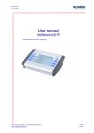
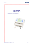
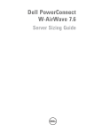
Dell PowerConnect W-6000 Power Supply Installation Guide The Dell PowerConnect W-6000 Power Supply adapts electrical power for use with the W-6000. The W-6000 chassis has three slots that can hold individual power supplies to support load sharing and fault tolerance. This chapter describes the general features and physical characteristics of the power supply and important power consumption management information. The final sections of the chapter cover the steps required to insert and remove power supplies. Features Rating The Dell W-6000 Power Supply (HW-PSU-400) is rated at 400 W total output and is auto-ranging to accept 85 to 264 VAC, at 50 to 60 Hz. Up to three 400 W power supplies can be installed in the W-6000. Load Sharing Load sharing occurs when more than one power supply of the same rating are installed in the W-6000 and turned on. Load sharing divides the total power load of the W-6000 among all plugged in power supply modules. Since the power supplies work together, the effective power capacity of the chassis is increased with each additional power supply. Redundancy When multiple power supplies are installed, if one becomes unavailable (fails, or is turned off or removed) the remaining power supplies will attempt to provide full power for the W-6000. If the total power load does not exceed the combined rated output of the remaining, operational power supplies, the W-6000 will continue to operate. For more information on power supply configurations, “Power Management” on page 3. Hot Swap Hot swapping should be performed by a trained technician. Hot swapping allows you to replace one failed power supply while the others provide full power. This makes it unnecessary to shut down the W-6000 during the replacement procedure. Hot swapping requires that after the target power supply is removed, the total power load does not exceed the combined rated output of the remaining power supplies. 0510766-01 | March 2011 1 Physical Description Figure 1 400W Power Supply 6.5A MAX O.T.P DC OK AC OK 1 2 3 4 5 6 7 1 1 Module Fastening Screws: These two captive fastening screws hold the power supply in place in the chassis. 2 Module Handle: This handle is used for removing or inserting the module into the W-6000 chassis. CAUTION: Do not use the power supply handle to lift or move the W-6000. Serious damage could result. 3 Indicator LEDs Table 1 400W Power Supply LEDs LED Name Position Status Description O.T.P. (Over Temp. Protection) Top Off Power supply temperature is okay. Red Power supply fan has failed or temperature is too high. DC OK Middle Green DC power output is okay. Red DC power output is not within tolerance. Green AC power input is okay. Red AC power input is not within tolerance. AC OK Bottom NOTE: In addition to the LEDs, the power supply status can be viewed using the CLI. 4 Air Intake Vent: This air intake vent helps the internal fan cool the power supply during operation. To prevent blockage, keep all material at least 10 cm (4 inches) from the vent. 5 Power Cord Retaining Clip: This clip fits over the power cord once the plug has been inserted into the power input socket. It helps prevent the power cord from being pulled out accidentally. CAUTION: Do not use the power cord retaining clip to remove the power supply module, or to lift or move the W-6000. 6 2 Power Input Socket: This power socket accepts power cords with standard IEC320 connectors. For proper safety and performance, the cord must be rated to 10 A and conform to grounded electrical standards in the country where the product is used. Dell PowerConnect W-6000 Power Supply | Installation Guide 7 Power Switch: The power switch has two states: Off () and On (|). Power Management The W-6000 supports up to three 400 W power supplies. If using one to two primary power supplies for 400 to 800 W of primary power, the use of a 400 W redundant power supply is possible. For maximum capacity planning, add the maximum power draw required for all of the modules in your chassis configuration to determine the required number of power supplies. M3 Module and PSU Configuration Table The following table displays the M3 module configurations, and the resultant power supply configurations and power usage. Table 2 Power Supply and W-6000M3 Configurations Module Number of Units M3 Controller Module (130 W max power draw each) 1 2 3 4 Total Power (W) 130 260 390 520 Required number of PSUs 1 1 1 2 Redundant number of PSUs 1 or 2 1 or 2 1 or 2 1 Inserting a Power Supply CAUTION: Many repairs may only be done by a certified service technician. You should only perform troubleshooting and simple repairs as authorized in your product documentation, or as directed by the online or telephone service and support team. Damage due to servicing that is not authorized by Dell is not covered by your warranty. Read and follow the safety instructions that came with the product. 1. Verify you understand the procedure and all precautions. Before beginning, read the entire procedure. Verify you understand all the precautions in these steps as well as those on page 10. 2. Select a power supply slot for the power supply. The 400 W power supply (HW-PSU-400) can be installed in any power supply slot and any power supply slot can be left empty. That is, there is no specific required order of slots used for power supplies. Figure 2 400 W Power Supplies Installed If replacing a previously installed power supply, first see “Removing a Power Supply” on page 5. If you are installing a power supply in an empty slot, you may have to remove the blank cover plate first. To do this, use a #2 Phillips or cross-head screwdriver. Turn the captive fastening screws on the faceplate counterclockwise until they are loose (they cannot be completely removed). Remove the cover plate and store it in a safe place. Dell PowerConnect W-6000 Power Supply | Installation Guide 3 3. Verify the power switch on the power supply to be installed is Off (). CAUTION: Never insert or remove a power supply while its power switch is in the On (|) position or if the power cord is plugged into the power supply module. Verify the power switch is Off () first and that the power cord is unplugged from the W-6000 PSU module. 4. Insert the power supply into the chassis. Grasp the power supply by the handle attached along the bottom side of the power supply, keeping the LEDs on the left and power switch on the right. Do not use the power cord retaining clip to insert or remove the power supply. Align the back of the module with the guide-rails in the chassis power supply slot and gently slide the module toward the backplane. Do not force the module; it should slide in easily most of the way. There may be moderate resistance when the power supply meets the connectors at the back of the chassis. Press firmly to engage the connectors, but do not use excessive force. 5. Secure the power supply. Use the screwdriver to push in the module’s captive fastening screws and turn them clockwise until moderate resistance is felt. Do not over-tighten. 6. Attach the power cord to the power supply. NOTE: Swing the cord retaining clip to the left before attaching the power cord. Plug an appropriate power cord into the power input socket. The socket accepts a power cord with a standard IEC320 plug. CAUTION: For proper safety and performance, the power cord must be rated to 10 A and conform to grounded electrical standards in the country where the product is operated. 7. Secure the power cord. When the power cord is attached, swing the power cord retaining clip to the right as shown in Figure 3 on page 4. This will hold the plug in place and help prevent it from being removed accidentally. Figure 3 Using the Power Cord Retaining Clip Right: Capture Cord Wrong: Around Plug Base 8. Attach the power cord to a proper electrical outlet. Verify that your site’s electrical systems can handle the power load. 4 Each power supply (HW-PSU-400) is rated at 400 W total and is auto-ranging to accept 85 to 264 VAC, at 50 to 60 Hz. Dell PowerConnect W-6000 Power Supply | Installation Guide Depending on the W-6000’s total power load, you may be required to increase the capacity of your site’s electrical systems. See “Power Management” on page 3 for details. CAUTION: For safety reasons, verify the power outlets and plugs are within easy reach of the operator and can be quickly disconnected if necessary. NOTE: Use of a power line conditioner or Uninterruptable Power Supply (UPS) can decrease or mitigate problems caused by power service fluctuations. Verify that the output of any power shaping device is compatible with the W-6000 power supplies. Removing a Power Supply CAUTION: Many repairs may only be done by a certified service technician. You should only perform troubleshooting and simple repairs as authorized in your product documentation, or as directed by the online or telephone service and support team. Damage due to servicing that is not authorized by Dell is not covered by your warranty. Read and follow the safety instructions that came with the product. 1. Verify that you understand the procedure and all precautions. Before beginning, read the entire procedure. Verify that you understand all the precautions in these steps as well as those on page 10. 2. Verify that the power switch on the power supply to be removed is in the Off () position. CAUTION: Never insert or remove a power supply while its power switch is in the On (|) position. Verify the power switch is Off () first. 3. Unplug the power supply to be removed. If using the power cord retaining clip, first swing it to the left and free of the plug. Then remove the plug. 4. Remove the power supply. Use a #2 Phillips or cross-head screwdriver to turn the power supply’s captive fastening screws counterclockwise until they are loose (they cannot be completely removed). Firmly grasp the handle of the power supply and carefully pull the module out of the chassis. 5. Cover blank slots. For safety considerations, as well as to promote proper air flow for cooling and to prevent dust from entering the chassis, cover any unoccupied slot with a blank cover plate. Dell PowerConnect W-6000 Power Supply | Installation Guide 5 Safety and Regulatory Compliance NOTE: For additionas safety, compliance, and regulatory information, see the Dell PowerConnect W-6000 Installation Guide. To download the latest technical product documentation, including User Guides, Reference Guides, and Installation Guides, navigate to support.dell.com/manuals Contacting Support Web Site Support Main Website dell.com Support Website support.dell.com Dell Documentation support.dell.com/manuals Copyright © 2011 Aruba Networks, Inc. AirWave®, Aruba Networks®, Aruba Mobility Management System®, and other registered marks are trademarks of Aruba Networks, Inc. Dell™, the DELL™ logo, and PowerConnect™ are trademarks of Dell Inc. All rights reserved. Specifications in this manual are subject to change without notice. Originated in the USA. Any other trademarks appearing in this manual are the property of their respective companies. Open Source Code Certain Aruba products include Open Source software code developed by third parties, including software code subject to the GNU General Public License (GPL), GNU Lesser General Public License (LGPL), or other Open Source Licenses. The Open Source code used can be found at this site: http://www.arubanetworks.com/open_source Legal Notice The use of Aruba Networks, Inc. switching platforms and software, by all individuals or corporations, to terminate other vendors' VPN client devices constitutes complete acceptance of liability by that individual or corporation for this action and indemnifies, in full, Aruba Networks, Inc. from any and all legal actions that might be taken against it with respect to infringement of copyright on behalf of those vendors. 6 Dell PowerConnect W-6000 Power Supply | Installation Guide