1
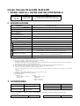
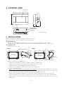
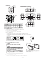
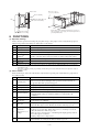
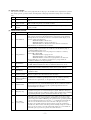
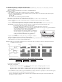
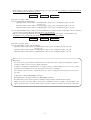
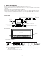
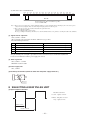
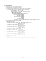
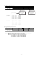
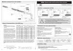
Manual No. ’06 . SC-T - 111
TECHNICAL MANUAL
Collection data
AIR CONDITIONING CONTROL SYSTEM
CENTER CONSOLE
SLA-3-ER (SC-SLA3-ER)
SLB-3-ER (SC-SLB3-ER)
-
3-
CONTENTS
1. MODEL USED ALL SUPER LINK RELATED MODELS ................................. 1
2. SPECIFICATIONS ........................................................................................... 1
3. ACCESSORIES ............................................................................................... 1
4. EXTERNAL VIEW ............................................................................................ 2
5. INSTALLATION ............................................................................................... 2
6. FUNCTIONS .................................................................................................... 4
7. ELECTRIC WIRING ......................................................................................... 9
8. SELECTING A NEW PULSE UNIT .................................................................. 10
These technical manual cover Center Consoles SLA-3-ER and SLB-3ER. Concerning other air conditioning control systems, see page 675
in Part 5 (Air Conditioning Control System) of the
’06
TECHNICAL MANUAL
KX-4
-
1-
Center Console SLA-3-ER, SLB-3-ER
1 MODEL USED ALL SUPER LINK RELATED MODELS
Name
Center Console
SLA-3-ER
SLB-3-ER
Model
Remark
SC-SLA3-ER
SC-SLA3-ER
If the SLA-3-ER and SLB-3-ER is buried, it
must be installed in a separately sold box (SLA3R-BX).
2 SPECIFICATIONS
Model
SLA-3-ER, SLB-3-ER(9)
Item
0 ~ 40 °C
Ambient temperature during use
Power supply
1 Phase 100V/200~240V 50Hz/60Hz
17 W
Power consumption
External dimensions
(Height⳯Width⳯Depth)
Net weight
162 mm ⳯ 240 mm ⳯ 110 mm
2 kg
Maximum number of connectable units
(Indoor units)
Maximum 48 units/system 3 systems = 144 units
Outputs
Inputs
LCD touch panel(4), (5)
SL (Super link) Signal inputs
(2)
Gas, Power pulse input
Fire signal input
(2)
Demand signal input(2)
Simultaneous operation
output
Simultaneous error output
Use with other central control units
Notes (1)
(2)
(3)
(4)
(5)
(6)
(7)
(8)
(9)
(10)
Color LCD, 7 inches wide
3 systems
8-point pulse width 100 ms or more
1 point non-voltage a contact input continuous input (closed, forced stop)
1 point non-voltage a contact input continuous input (closed, demand control)
1 point maximum rated current 40 mA, 24 V
During full stop: Open; If even 1 unit is operating, Closed
1 point maximum rated current 40 mA, 24 V
Normal: If even one unit is abnormal, Open(6)
(8)
Some functions cannot be used depending on the indoor model used.
The receiving side power supply is DC 12 V (10 mA).
If the energy consumption calculation function is necessary, use the SLB-3-ER.
The lifetime of the keying of touch panel is one million times.
The lifetime of LCD is about 20,000 hours. depending also upon the backlight OFF time setting. (The brightness will become half of the starting value.)
The touch panel has an endurance of approximately 1 million times.
In the environment setting screen, it is also possible to change the batch error output setting as open for normal and closed for error.
The air conditioning charges calculations of this unit are not based on OIML, the international standard.
• The center console SLA-2A series can be connected 1 unit per system.
• It cannot be combined with the center console SLA-1 series, SLA-200 series and the CHC-M series, SC-WGW-A series, SC-BGW-A series or SC-LIF
series,
SC-LGW-A series.
• Multiple SLA-3-ER and SLB-3-ER units cannot be connected on the same network.
SLB-3-ER cost calculation results cannot be guaranteed.
Working Environment
• Operating System
Microsoft® Windows® 2000 SP3, 4
Windows® XP
• Hardware
Pentium 300 MHz or greater
128 MB RAM
5 MB free hard disk space
1 USB (1.1 or 2.0) port
3 ACCESSORIES
Center console
Pan head screw (M4)
Pan head screw (M4)
1 unit
4 pieces for installing on the
control board (10 mm)
4 pieces for embedding in
a wall (40 mm)
User's manual (CD-ROM)
Installation Instruction manual
Terminal
1 unit
1 unit
2 pieces
In case of embedding in a wall, the special box (SLA3R-BX) for embedding in a wall is required. (sold separately)
• For SLB-3-ER
SLB-3-ER utility (CD-ROM)
1 unit
USB Memory
-
1-
1 unit
4 EXTERNAL VIEW
7-inch wide color
LCD touch panel
240
162
Wall surface
40
70
USB
Upper case mounting
screws(2 screws)
Terminal block
Paint color:Pearl white
5 INSTALLATION
Before the installation, shut off the power supply to avoid an electric shock.
Please locate or protect so that the unit will not be forced against wiring.
(1) Installation place
Install this unit indoors without the influence of the electromagnetic wave, or splashing such as water and dust.
Necessary clearance is 200mm or more beneath the center console and 500mm or more in front of the center console.
(2) Installation space
Please choose one of two ways.
4-ø6
Holes for the unit installaion
218
<Way2>
SLA3R-BX
Inner wall
229
198
15.5
Opening space
for the installation
105
99
6
6
15.5
120
<Way1>
154
120
Opening space
for the installation
SLA3R-BX
6
186
6
6
Inner wall
6
170
4-ø6
Holes for the unit installaion
(a) In case of installing on the control board
1) Please use the control board of the size of 300mm ⳯ 400mm ⳯ 120mm or larger.
2) Please be sure to lock the control board to protect persons from the electric shock.
3) Please do not use any heat insulation material on the control board.
4) If you use it, accumulated heat will cause the center console to malfunction.
(b) In case of embedding in a wall
Please be sure to use the special box, SLA3R-BX (sold separately) to secure sufficient air circulation space. If the box is
unused, the center console will not work properly because of heat buildup inside the box. Please be sure to use for protecting
persons from the electric shock.Please check that the sufficient space is available in the wall.
When the inside of the wall is divided and have a cavity, please create space more than 0.08m3. Refer to the next page.
If there is no partition on the left, right, top and bottom of the center console, please create a space that is 105mm ordeeper.
When you cannot create the sufficient space or thickness of the wall is above 15mm, please install the center console on the
control board.
-
2-
<No partition>
Inner wall
䢇SLA3R-BX (Sold separately)
Beam of
building
178
25
15 50
80
15
25
more than
105mm
SLA3R-BX
15
228
220
48 17
<With partition>
17 48 15
2-ø35
(Knock out)
20
20
4-ø6
20
Center
console
b
70
155
170
198
c
Inner wall
a(Height)(mm) b(Width)(mm) c(Depth)(mm) Space(m3)
0.08
800
110
900
0.08
400
110
1800
0.08
400
200
1000
600 or larger 400 or larger 110 or larger
30
Example1
Example2
Example3
Minimum
54
120
54
(3) Installation method
(a) Embed signal wire and power supply wire in a wall beforehand.
(b) Connect wires to the terminal block.
(c) Confirm power supply voltage and connect correctly.
(d) Remove the upper case
1) Take out two screws using a cross slot screwdriver. (Don't lose the screws)
2) Pull the upper case a little forward and push above. Then, upper case can be removed.
1 Caution
Please do not
install facing
upward or in
slanted position.
3
2
Correct
Incorrect
113
20
153
113
a
132
60
Partition
Incorrect
1
(e) In case of installing on the control board
M4 screws, 4 pieces
(accessory of the unit)
1 Caution
Please do not install other units on the same
control board that will cause temperature rise.
2 Caution
Please do not install multiple controllers on the
same control board. They can cause the temperature
rise of the control board interior and the center
consoles will not work properly.
When there is no choice but to install the multiple
controllers,please adjust the tempereture inside the
control board 40 degrees or less. (for example
cooling fan installation)
Fix the unit to the SLA3R-BX with the M4 screws. (4 places)
Wire separately the power supply wire and the signal wire for
preventing malfunctions.
(f) In case of embedding in a wall
Please be sure to use the special box, SLA3R-BX (sold separately).
-
3-
Electric wires
M4 screws, 4 pieces
(accessory of the unit)
Beam of building
Fix the SLA3R-BX to the
beam in the building
Unit
Inner wall
40
Unit
Fix the unit to the SLA3R-BX with the M4 screws.(4 places)
Wire separately the power supply wire and the signal wire for
preventing malfunctions.
More than 105mm
6 FUNCTIONS
(1) Operation, Settings
Carries out batch operation and settings in group units for up to 144 groups. It is necessary that the groups for
which batch operation and settings are carried out be set in advance.
No.
1
2
3
4
5
6
7
Item
Contents
Run/Stop
Starts or stops operation.
Mode
Set temperature
Sets COOL, HEAT, DRY, FAN and AUTO(1) operation.
Sets the temperature in a range of 18 °C ~ 30 °C (in 1 °C units).
Operation permitted/
prohibited(2)
Enables or disables manual operation, enables or disables run/stop operations,
enables or disables mode setting and enables or disables temperature setting.
Fan speeds
Sets Hi, Me or Lo fan speed.
Sets auto swing ON or OFF and sets positions 1 ~ 4.
Resets (turns off) the filter sign.
Air direction
Filter reset
Notes (1) This function can be applied to the outdoor units, which are the cooling/heating free multi KXR, GHP-R series or later and PAC.
(2) This function can be applied to the indoor units, which are the model KXE4 or later, and to the remote controller, which is the
model RC-E1 or later.
(3) This enables or disables permiting and prohibiting the individual operation such as RUN/STOP mode and temperature settings of
the remote controller.
(2) Status monitor
Status monitoring is carried out in block units (only monitored operating state and breakdown), group units or
air conditioner units.
No.
Item
1
Operating state
2
3
4
Mode
Set temperature
Room temperature
5
Operation enabled
6
Fan speeds
7
Air direction
8
Filter sign
9
Maintenance
(Inspections 1, 2 or
backup)
10
Breakdown
Contents
Monitors the operating and stopped state of the air conditioner.
When 1 or more units is running, it shows operation and when all units are
stopped, it shows that operation is stopped.
Displays the operation mode of a representative air conditioner.
Displays the set temperature of a representative air conditioner.
Displays the return air temperature of a representative air conditioner.
It shows whether manual operation, the run and stop operation, mode setting
and temperature setting are enabled or disabled of a representative air
conditioner.
Displays the fan speed setting for a representative air conditioner.
Displays the auto swing ON/OFF setting and position setting for a
representative air conditioner.
Displays the filter sign if the filter sign for one or more units is lighted up.
When the filter sign is off for all units, the monitor's filter sign goes off.
Displays the maintenance indicator when the <Inspection 1, 2 or backup>
lights up on 1 or more units. When <Inspection 1, 2 or backup> is off on all
units, the maintenance indicator goes off.
Three are 3 types of inspection, 1, 2 and backup. The display priority order for
these three types is as follows.
Backup > Inspection 1 > Inspection 2
Displays the breakdown indicator when one or more units has broken down.
When all units are normal, the breakdown indicator goes off.
-
4-
(3) Setting the schedule
The operation schedule can be set in group units. In one day, up to 16 schedules can be registered for operation
time, run/stop, mode, operation enable, and temperature settings. Operation time settings can be set in minute
units.
No.
Item
1
Yearly schedule
2
Today's schedule
3
Special day
schedule
Contents
Set the schedule for one year as weekdays, holidays, special day 1 and special
day 2.
Sets the schedule that will be valid for the current day only.
This schedule has priority over annual schedules.
Sets each schedule of weekday, holiday, special day 1 and special day 2 in the
yearly schedule.
(4) Administration, Control
No.
Contents
Item
Block definition
Sets the block name and the groups constituting the block.
The groups registered in a block must first be registered by group definition.
Groups that are not set in blocks cannot be set in detail from the display of all
blocks or their status displayed.
• Maximum number of blocks is 16
• Maximum number of groups per block is 9
• Maimum number of characters in a block name is 16 characters.
The initial state is with all blocks not defined.
2
Group definition
Sets the group name and the air conditioners constituting the group (up to 16
units per group), a representative air conditioner, and whether the group is
controlled simultaneously or not.
Air conditioners which are not set in groups are not subject to control by
SLA-3-ER or SLB-3-ER.
• Maximum number of groups is 144
• Maximum number of air conditioners per group is 16
• Maximum number of characters in a group name is 16 characters.
In the initial state, 1 air conditioner is assigned to 1 group, and the air
conditioner number is for the group name.
3
Unit definition
The type of energy consumption and capacity of each air conditioner connected
to SLB-3-ER, and whether it is subject to demand control or not, are set.
4
Time and data
setting
Sets the clock used for the schedule, etc.
Annual (Anno Domini) / Month / Day / Hour (24 hr. system) / Minute
5
Alarm history
Displays the error occurrence and recovery history for up to 300 occasions in air
conditioner units.
6
Energy consumption
calculation period
Sets the "regular hours" time bands used for calcuation.
7
Energy consumption
calculation cumulative
operation time
Calculates the cumulative operating hours for each air conditioner, dividing
them between "regular hours" or "irregular hours," and saves them.
Demand control
"Starts the fan" or "Prohibits operation" for air conditioners which have
previously been set by external demand signals. The air conditioners return to
their original status (Mode and operation permitted/prohibied) when the
demand signals are cancelled.
Emergency stop
Causes all the air conditioners connected to this unit to "Stop" or "Prohibits
operation" in response to an external emergency signal. When the emergency
signal is cancelled, the air conditioners return to their original setting permitting
or prohibiting manual operation, but all unit remain in the "Stop" state.
Power failure
recovery control
When the power is turned on again after a power failure, the groups set in the
schedule operate in accordance with the schedule that was set most recently
prior to the power failure. If Run/Stop, the operation mode, operation permitted
and set temperature items are not set and "-----" is displayed for that item, the
time is set to the time that was closest to the time of the power recovery.
If there is no schedule setting for the affected date, in the air conditioner’s
default state, all the remote controller operation enabling settings are enabled.
Also, it is not necessary to reset the current time if there is a power failure in
which the power goes off for a period of less than 48 hours.
1
8
9
10
-
5-
(5) Energy consumption calculation data (SLB-3-ER)
SLB-3-ER outputs energy consumption calculation data using USB memory. These data can be edited using commercial
spreadsheet software.
Energy consumption calculation data are created for each individual month.
<Calculation procedure>
1 The cumulative operating time is calculated for each air conditioner. (in minutes)
2 The total operating time (Ki) for each air conditioner, and the operating time in each time band (regular hours, irregular
hours) are calculated (in minutes).
Ki = Ki + KM
KM = Amount of air conditioner operation in 1 minute.
The amount of operation is calculated by the following 3 methods.
The amount of operation in the case calculated for the rated opening area value for that air conditioner, E.
• MULTI 1: The conversion value considering the amount of refrigerant flowing in the indoor unit is calculated
(∑ E j).
(Ej: Conversion value for the opening area of the indoor unit's expansion valve.)
• MULTI 2: The time that refrigerant flows through the indoor unit is additionally calculated. (Thermostat ON time⳯E)
• RUN/STOP: A conversion value for the time when the remote controller is ON is added. (Operating time⳯E)
(E: Conversion value for the capacity of the indoor unit.)
• Use the same kind of flow volume for the same type of dynamic flow meters (gas meters).
• If MULTI-1 and MULTI-2 are set, indoor units in the blower mode cease to be objects of proportional division.
Set indoor units in the blower mode to ON or OFF if you
USB
want to make them objects of proportional division.
• As for the standby power in the case that the air conditioner is
not used at night, etc. proportional division cannot be applied
if there are no indoor units running, so the standby power
readings will not match. Recalculate using spreadsheet
software.
• Simple software is included for editing the energy consumption calculation
data.See the included software concerning the operation method.
Bottom of the unit
• Energy consumption calculation data are obtained from this unit using the USB memory.
(SLB-3-ER does not recognize commercial USB memory.)
(Example) Method of proportional distribution in case of indoor units A, B, C operating as follows (the shaded part indicates the
accumulated operating volume).
1 In case of MULTI 1 setting: Conduct proportional distribution according to the results of accumulated answer Hz.
Accumulation is not performed when the thermo is OFF or during the Fan mode operation.
Indoor unit A
Indoor unit B
Indoor unit C
25Hz
40Hz
60Hz
Total value of operating volume
(Total value of answer Hz)
Operating volume of indoor unit A = accumulated pulse counts⳯power consumption per pulse⳯25 / 125
(25 + 40 + 60)
Operating volume of indoor unit B = accumulated pulse counts⳯power consumption per pulse⳯40 / 125
Operating volume of indoor unit C = accumulated pulse counts⳯power consumption per pulse⳯60 / 125
2 In case MULTI 2 setting: Conduct proportional distribution according to the Hz corresponding to the air conditioner capacity
(capacity equivalent Hz: fixed value) and thermo ON operating time.
Capacity equivalent Hz: equivalent value of answer Hz when exerting the indicated capacity of indoor unit (fixed value
determined according to capacity).
-
6-
Different from 1, the fixed value is accumulated irrespective of the answer Hz. Accumulation is not performed when the
thermo is OFF and during the Fan mode operation.
Indoor unit A
Indoor unit B
Indoor unit C
30Hz
50Hz
70Hz
Total value of operating volume
(capacity equivalent Hz⳯thermo ON time)
Operating volume of indoor unit A = accumulated pulse counts⳯power consumption per pulse⳯30 /150
(30 + 50 + 70)
Operating volume of indoor unit B = accumulated pulse counts⳯power consumption per pulse⳯50 / 150
Operating volume of indoor unit C = accumulated pulse counts⳯power consumption per pulse⳯70 / 150
3 In case of RUN/STOP setting: Conduct proportional distribution according to the Hz corresponding to the air conditioner
capacity (capacity equivalent Hz: fixed value) and remote controller ON time.
Same as 2, the capacity equivalent Hz (fixed value) is accumulated according to the remote controller ON time only.
Accumulation is also performed when the thermo is OFF and during the air supply operation.
Indoor unit A
Indoor unit B
Indoor unit C
40Hz
60Hz
70Hz
Total value of operating volume
(capacity equivalent Hz⳯remote controller ON time)
Operating volume of indoor unit A = accumulated pulse counts⳯power consumption per pulse⳯40 / 160
(40 + 50 + 70)
Operating volume of indoor unit B = accumulated pulse counts⳯power consumption per pulse⳯50 / 160
Operating volume of indoor unit C = accumulated pulse counts⳯power consumption per pulse⳯70 / 160
夝 User login
For owners the fee apportionment for multi machine air conditioners is more complicated and harder to explain to
customers. In many cases it's best to use simple explanations.
In addition, consumption for multi machines are calculated based on volume, making it easy for excessive cooling
and differences in building load to lead to discrepancies in electricity consumption.
These different values are hard to explain. Therefore, it is easier to explain how many horsepower were used for
how long.
At this point, recommend [RUN/STOP] registration.
Both multi machines and single machines use [RUN/STOP] registration.
Recommend that separate electricity meters be installed for single machine and multi machine systems.
Display every unit of electricity (kW) on the electricity consumption board. For example, register P280H as 28.0.
Current operational value = electricity volume⳯time of operation, calculated according to the electricity volume ratio.
-
7-
<Flow of data processing>
Power consumption meter
with pulse signal transmitter
Pulse input (Max. 8 systems)
The energy consumption caculated by this equipment close not
conform to OIML.
This unit calculates only energy consumption (gas,electric power).
You need to calculate the air-conditioning rates.
Pulse width: 100ms and above
Pulse parameter: 0.01 - 300.00kWh / pulse (electrical)
0.01 - 10.00m3 / pulse (gas)
SLB-3-ER
Input to SLB-3-ER
1 Air conditioner capacity (kW) input
2 Program block setting (1 - 16)
3 Group setting (1 - 144)
4 Proportional distribution calculation
method (defined by air conditioner)
SLB-3-ER
Read the "frequency of
pulse input", "operate /
stop of each indoor unit",
"answer Hz of each
indoor unit" every minute.
USB memory
Accumulated daily pulse counts
Accumulated pulse counts are renewed every minute
according to the following calculation method.
( = pulse counts accumulated up to now + frequency of
pulse input this time)
(*)
Accumulated daily operating volume
Accumulated operating volume of each indoor unit is
renewed every minute according to the following
calculation method.
( = operating volume accumulated up to now + frequency
of pulse input this time)
(Binay form)
PC
Conversion
a. (Group) Definition file (CSV format)
(Group name, Group composition)
b. Monthly data file (CSV format)
b-1: Daily operating time (minutes), calculated value of the air conditioner for each
period (the basis period and the overtime), in the SL#1-SL#3 system
b-2: Daily cumulative pulses from meters (#1-#8) for each period.
(Save)
(Text format)
1. Calculates the daily energy consumption of
air conditioners for each meter group.
2. Calculates the daily operating time and the
daily energy consumption for each air
conditioner.
3. Calculates the daily operating time and the
daily energy consumption for each air
conditioner group.
4. Calculates the daily operating time and the
daily energy consumption for each air
conditioner group in the specified period.
PC input
1 Pulse meter (electricity or gas) group definition
2 Pulse constant definition (kWh / pulse, m3 / pulse)
3 Setting of the calculation period
(the end of the month, the 20th of the month, or etc.)
c. The daily energy consumption of air conditioners for each meter group
(Palse1-Palse8)
d. The daily operating time (minutes) and the energy consumption for each air
conditioner (SL#1-SL#3)
e. The daily operating time (minutes) and the daily energy consumption for each air
conditioner group (Group#1-Group#144)
f. The monthly operating time (hour) and the energy consumption for each air
conditioner group in the specified period.
(Save)
(Text format)
Customer processing
4 Group definition for each tenant
5 Setting of energy charge (the unit price and the basic charge of
electricity and gas)
6 The sheet form of a bill
Calculating the air conditioner's energy charge.
Printing out the bill of a tenant.
Note (1) The calculation results for the SLB-3-ER are not guaranteed.
Working Environment
• Operating System
Microsoft® Windows® 2000 SP3, 4
Windows® XP
• Hardware
Pentium 300 MHz or greater
128 MB RAM
5 MB free hard disk space
1 USB (1.1 or 2.0) port
-
8-
7 ELECTRIC WIRING
For safety's sake, use the round crimping terminal with the insulation sleeve for wiring to the unit.
• Perform ground wiring. Please do not connect the ground wire to the gas pipe,the water pipe, the lightning rod, and the telephone
ground wire.
• Please do not turn on the power supply (hand switch) until all work finishes.
• Please turn on the power supply two minutes or more after turning on the power supply of the indoor unit and the outdoor unit.
• All wiring,switches, relays, power supply,and lamps, shown in the figure, besides SLA-3-ER (SLB-3-ER), are to be purchased.
• A readily accessible disconnect device shall be in corporated in the building installation wiring.
• Please be sure to use the terminals that comes with this unit for wiring to the terminal block of the power supply.
(1) Wiring outline
3 Super Link
systems
Power supply
AC100-240V
50/60Hz
Power
supply
L1, L2
Hand switch
(10A)
Operation output
Power
supply
Error output
The calculating data taken out by way of USB memory
(accessory of SLB-3-ER)
Ground wiring
Emergency stop signal input
Power pulse input from gas meter or wattmeter
(8 points) (in case of SLB-3-ER)
Demand signal input
(2) System wiring
Back of the unit
Terminal block
(two tiers)
Ground
position
2 4 6
1 3 5
8 10 1214 16 18 20 22 24 26 28 30 32 34 36 38
7 9 11 13 15 17 19 2123 25 2729 3133 3537 39
(a) The upper tier of terminal block
L1
L2/N
2
4
DO1
6
Please be sure to
use the accessory
terminals.
Power supply
AC100-240V
50/60Hz
D1-
DO2
D2-
14
8
10
12
+ (*1)
+ (*1)
Power
Power
supply
supply
Operation
output(O1)
(*2)
COM
DI1
COM
DI2
16
18
20
22
24
26
A1
B1
A2
B2
A3
B3
28
30
32
34
36
38
Super link system 3
(*3)
(*3)
Error
Demand signal Emergency stop signal
output(O2) input(I1)
input(I2)
Super link system 2
Super link system 1
Note (1) (*1) Power supply : DC 24V maximum rating current : 40mA.
(2) (*2) Factory default of error output (normal operation) is closed status.You can choose "Open" status for malfunction output during normal operation.
Please refer to the user's manual.
(3) (*3) No-voltage a-contact input Contact capacity : DC12V, 10mA.
-
9-
(b) The lower tier of terminal block
1
3
5
COM
PI1
COM
PI2
COM
PI3
COM
PI4
COM
PI5
COM
PI6
COM
PI7
COM
PI8
7
9
11
13
15
17
19
21
23
25
27
29
31
33
35
37
39
Power input from gas meter or wattmeter (8 points)
(in case of SLB-3-ER)
Note (1) Do not connect power supply wire to another terminal block.When you connect by mistake,damage and damage by fire of the electric part are
caused, and it is very dangerous. Please check the wiring thoroughly again before it turns on power.
(2) Please connect the gas meter or the wattmeter that satisfies the specification below.
• The meter with pulse transmitter.
• The meter with pulse width of 100 ms or more.
The energy consumption calculated by this unit does not conform to OIML, and there are no guarantees concerning the results of the calculations.
(3) Signal wire for super link
• Size; 0.75mm2 ~ 2.0mm2
• The total length of the signal wires should be 1000 m or less. (per line)
• Recommended signal wire list
No.
Name
Symbol
1
Vinyl cabtire roung cord
VCTF double-core 0.75 to 2 mm2
2
Vinyl cabtire round cable
VCT double-core 0.75 to 2 mm2
3
Control vinyl insulated, vinyl sheathed cable
CVV double-core 0.75 to 2 mm2
4
Shielding wire
MVVS double-core 0.75 to 2 mm2
When No. 4 shielding wire is used, always ground the single wire side of the shielding wire. In addition,
using the shielding wire is helpful to prevent the incorrect connection between 5V DC and 220/240V AC
because the discrimination from the power supply wire is clear.
(4) Other signal wire
• Size; 0.75mm2 ~ 1.25mm2
• Maximum extension: 200m
(5) Power supply wire
• Size; 1.25mm2
(6) Round eye-let terminal (Terminals other than the power supply terminals.)
max
6.0
min ø3.2
8 SELECTING A NEW PULSE UNIT
(a) Input acceptor restrictions
Machine restrictions
1second : 5 pulses or fewer
1minute : 300 pulses or fewer
1day: 1 pulse or more
100 ms or more
200 ms or more
-
10 -
(b) Pulse unit selection
1 Find the total capacity of all connected air conditioners
2 Assume that the correct electricity meter is being used
3 Air conditioners operating at full load: assume summer overload power consumption⳯1.2
For example, Set the total electricity consumption = 100kW, power rate = 90%
Operating at full load = 100⳯1.2 = 120kW
With 3 in conjunction, 1 = 120⳯1000/ (1.732⳯200⳯0.9) = 385A
→ Electricity meter must be 400A
If you use 400A Mitsubishi transmission equipment, then
• K11 type, pulse unit at 100kWh/P
select while at 10kWh/P
• K11 type, pulse unit at 100kWh/P
10kWh/P
select while at 1kWh/P
• There are other products with smaller pulses, ask an electric meter manufacturer for details.
4 Inspection while electricity consumption is at 120kWh
● When pulse input is highest
Use 0.1kWh/P, then 1200P/h = 20P/min exactly 1 minute 20 pulse (300pulses or fewer)
10 minutes 200 pulses OK
Use 1kWh/P, then 120P/h = 2P/min exactly 1 minute 2 pulses
10 minutes 20 pulses OK
Use 10kWh/P, then 12P/h = 0.2P/min , so 1 minute no pulses
10 minutes 2 pulses OK
● Lower usage rate, for example 1/10 time (12kWh),
Use 0.1kWh/P, then 120P/h = 2P/min so 1 minute 2 pulses
10 minutes 20 pulses OK
Use 1k h/P, then 12P/h = 0.2P/min , so no pulses in 1 minute
10 minutes 2 pulses OK
Use 10k h/P, then 12P/h = 0.2P/min , so 1 minute no pulses
10 minutes no pulse NG
5 Pulse units should reach 0.1kWh/P.
• 10kWh/P is NG.
• 1kWh/P usage rate is the lowest, there might not be any pulses in 10 minutes, causing a calculation error.
-
11 -
(c) Largest gas pulse input value
Gas amount pulse unit
0.01m3/P
0.05m3/P
0.1m3/P
0.5m3/P
Largest measurable
flow volume
4,320m3/B
21,600m3/B
4,3200m3/B
21,6000m3/B
180m3/h
900m3/h
1,800m3/h
9,000m3/h
900/7=128 times
2m3/h
3m3/h
5m3/h
7m3/h
If you use
If you use
If you use
If you use
0.5m3/P time:
If you use 10m3/h
If you use 15m3/h
If you use 30m3/h
If you use 50m3/h
If you use 90m3/h
If you use 120m3/h
Largest used flow
10~120m3/h
Largest used flow
2~7m3/h
gas meter example
0.05m3/P time:
9000/120=75 times
40 pulse/h
60 pulse/h
100 pulse/h
140 pulse/h
20 pulse/h
30 pulse/h
60 pulse/h
100 pulse/h
180 pulse/h
240 pulse/h
(d) Largest electric pulse input value
Gas amount pulse unit
0.01kWh/P
0.1kWh/P
1kWh/P
10kWh/P
Largest measurable
flow volume
4,320kWh/B
43,200kWh/B
432,000kWh/B
4320,000kWh/B
180kWh/h
1,800kWh/h
18,000kWh/h
180,000kWh/h
Note (1) Electricity meter pulse unit, please select 10kWh/P or less.
(Example) using 3 phase 200V– 30A electric meters, power rate at 100%, largest flow will be 30A
Electricity consumption = 3⳯200⳯30⳯1.0 = 10, 392 kWh
This time, set to 0.1kWh/P, so 103, 920P/h = 1730 pluse/minute NG
Set to 1.0kWh/P , so 10, 392P/h = 173 pluse/minute OK
Set to 10.0kWh/P, so 1, 039P/h = 17.3 pluse/minute OK
-
12 -
Air-Conditioning & Refrigeration Systems Headquarters
16-5, 2-chome, Kounan, Minato-ku, Tokyo, 108-8215, Japan
Fax : (03) 6716-5926
-
2-
No.042(2A) R