1
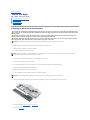
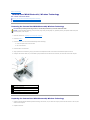
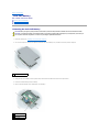
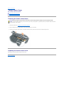
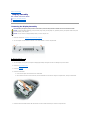
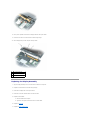
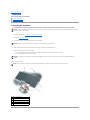
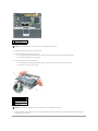
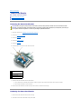
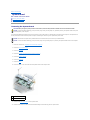
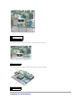
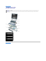
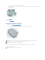
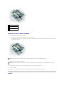
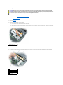
Dell™ Latitude™ D410 Service Manual
Before You Begin
System Components
Internal Card With Bluetooth® Wireless Technology
Hard Drive
Memory Module and Modem
Coin-Cell Battery
Center Control Cover
Keyboard
Mini PCI Card
Display Assembly
Palm Rest
Fan
Smart Card Reader
System Board
Pin Assignments for I/O Connectors
Flashing the BIOS
Notes, Notices, and Cautions
NOTE: A NOTE indicates important information that helps you make better use of your computer.
NOTICE: A NOTICE indicates either potential damage to hardware or loss of data and tells you how to avoid the problem.
CAUTION: A CAUTION indicates a potential for property damage, personal injury, or death.
Information in this document is subject to change without notice.
© 2005 Dell Inc. All rights reserved.
Reproduction in any manner whatsoever without the written permission of Dell Inc. is strictly forbidden.
Trademarks used in this text: Dell, the DELL logo, and Latitude are trademarks of Dell Inc.; Intel is a registered trademark of Intel Corporation; Bluetooth is a trademark owned by
Bluetooth SIG, Inc. and is used by Dell Inc. under license.
Other trademarks and trade names may be used in this document to refer to either the entities claiming the marks and names or their products. Dell Inc. disclaims any
proprietary interest in trademarks and trade names other than its own.
January 2005 Rev. A00
Back to Contents Page
Before You Begin
Dell™ Latitude™ D410 Service Manual
Preparing to Work Inside the Computer
Recommended Tools
Computer Orientation
Screw Identification
Preparing to Work Inside the Computer
CAUTION: Only a certified service technician should perform repairs on your computer. Damage due to servicing that is not authorized by Dell is
not covered by your warranty. Read and follow applicable instructions in the safety instructions in the Product Information Guide that came with
the computer.
CAUTION: To prevent static damage to components inside your computer, discharge static electricity from your body before you touch any of
your computer's electronic components. You can do so by touching an unpainted metal surface.
CAUTION: Handle components and cards with care. Do not touch the components or contacts on a card. Hold a card by its edges or by its metal
mounting bracket. Hold a component such as a microprocessor by its edges, not by its pins.
NOTICE: To avoid damaging the computer, perform the following steps before you begin working inside the computer.
1.
Ensure that the work surface is flat and clean to prevent scratching the computer cover.
2.
Save any work in progress and exit all open programs.
3.
Turn off the computer and all attached devices.
NOTE: Ensure that the computer is turned off and not in a power management mode. If you cannot shut down the computer using the computer
operating system, press and hold the power button for 4 seconds.
4.
If the computer is connected to a Media Base or other docking device, undock it.
5.
Disconnect the computer from the electrical outlet.
6.
To avoid possible damage to the system board, wait 10 to 20 seconds and then disconnect any attached devices.
7.
Disconnect all other external cables from the computer.
8.
Remove any installed PC Cards from the PC Card slot.
9.
Close the display and turn the computer upside down on a flat work surface.
NOTICE: To avoid damaging the system board, you must remove the main battery before you service the computer.
10.
Slide the two battery-bay latch releases on the bottom of the computer, and then remove the battery from the battery bay.
11.
Remove any installed memory modules or Mini PCI cards.
12.
Remove the hard drive.
Recommended Tools
The procedures in this manual require the following tools:
l
#1 Phillips screwdriver
l
¼-inch flat-blade screwdriver
l
Small plastic scribe
l
Flash BIOS update program CD or USB memory key with the flash BIOS update program.
Computer Orientation
1
front
2
left
3
back
4
right
Screw Identification
When you are removing and replacing components, print "Screw Identification" as a tool to lay out and keep track of the screws. The placemat provides the
number of screws and their sizes.
Modem:
Hard Drive:
Keyboard:
(1 each)
(2 each — hard drive)
(2 each)
(2 each — hard drive carrier)
Display Assembly (top — hinges):
Palm Rest (top):
Fan:
(2 each — M2 x 6 mm)
(5 each — M2.5 x 5 mm)
(3 each)
(1 each — M2 x 3 mm)
Display Assembly (bottom — computer base): Computer Base:
System Board:
(2 each — M3 x 5 mm)
(3 each)
(12 each — M2.5 x 5 mm)
door for internal card with Bluetooth® Wireless Technology
(1 each — M2 x 3 mm)
Back to Contents Page
Back to Contents Page
Flashing the BIOS
1.
Ensure that the AC adapter is plugged in and that the main battery is installed properly.
NOTE: If you use a BIOS update program CD to flash the BIOS, set up the computer to boot from a CD before inserting the CD.
2.
Insert the BIOS update program CD, and turn on the computer.
Follow the instructions that appear on the screen. The computer continues to boot and updates the new BIOS. When the flash update is complete, the
computer will automatically reboot.
3.
Press <F2> during POST to enter the system setup program.
4.
Press <Alt><F> to reset the computer defaults.
5.
Press <Esc>, select Save changes and reboot, and press <Enter> to save configuration changes.
6.
Remove the flash BIOS update program CD from the drive and restart the computer.
Back to Contents Page
Back to Contents Page
Internal Card With Bluetooth® Wireless Technology
Dell™ Latitude™ D410 Service Manual
Removing the Internal Card With Bluetooth® Wireless Technology
Replacing the Internal Card With Bluetooth® Wireless Technology
Removing the Internal Card With Bluetooth® Wireless Technology
CAUTION: Before performing the following procedures, read the safety instructions in your Product Information Guide.
NOTICE: To avoid electrostatic discharge, ground yourself by using a wrist grounding strap or by periodically touching an unpainted metal surface (such
as the back panel) on the computer.
1.
Follow the instructions in "Preparing to Work Inside the Computer."
2.
Remove the battery.
3.
Remove the door for the internal card with Bluetooth® wireless technology:
a.
Loosen the captive screw on the card door.
b.
Lift out the card door.
4.
Remove the M2 x 3-mm card screw.
5.
Using a plastic scribe or screwdriver, gently pry the card from its compartment and lift out the card from underneath the captive-screw hole.
6.
Holding the card with one hand, use your other hand to gently disconnect the card from the card connector, and remove the card from the computer.
1 door for internal card with Bluetooth® wireless technology
2 captive screw on card door
3 card connector
4 internal card with Bluetooth® wireless technology
5 M2 x 3-mm screw
Replacing the Internal Card With Bluetooth® Wireless Technology
1.
2.
Holding the internal card with Bluetooth® wireless technology with one hand, use your other hand to gently connect the card connector to the card, and
insert it into the computer.
Replace the card door.
3.
Replace the battery.
Back to Contents Page
Back to Contents Page
Coin-Cell Battery
Dell™ Latitude™ D410 Service Manual
Removing the Coin-Cell Battery
Replacing the Coin-Cell Battery
Removing the Coin-Cell Battery
CAUTION: Before you begin any of the procedures in this section, follow the safety instructions located in the Product Information Guide.
CAUTION: To prevent static damage to components inside your computer, discharge static electricity from your body before you touch any of
your computer's electronic components. You can do so by touching an unpainted metal surface.
1.
Follow the instructions in "Preparing to Work Inside the Computer."
2.
Turn over the computer, loosen the two captive screws from the coin-cell battery cover, and lift the cover away from the computer.
1
captive screws (2)
3.
Gently pull the coin-cell battery from the system board, and disconnect the cable connector from the system board.
4.
Remove the double-sided tape from the battery.
5.
Place the double-sided tape on the replacement coin-cell battery.
1 coin-cell battery
2 battery cable connector
3 battery cable
Replacing the Coin-Cell Battery
1.
Affix the replacement battery with the double-sided tape on the system board.
2.
Replace the coin-cell battery cover.
Back to Contents Page
Back to Contents Page
Center Control Cover
Dell™ Latitude™ D410 Service Manual
Removing the Center Control Cover
Replacing the Center Control Cover
Removing the Center Control Cover
CAUTION: Before you begin any of the procedures in this section, follow the safety instructions located in the Product Information Guide.
NOTICE: To avoid electrostatic discharge, ground yourself by using a wrist grounding strap or by periodically touching an unpainted metal surface (such
as the back panel) on the computer.
1.
Follow the instructions in "Preparing to Work Inside the Computer."
2.
Open the display all the way (180 degrees) so that it lies flat against your work surface.
3.
Starting on the right side of the computer, use a plastic scribe to gently pry up the center control cover. Unsnap from right to left.
Replacing the Center Control Cover
Gently snap the cover back in place starting from left to right.
Back to Contents Page
Back to Contents Page
Display Assembly
Dell™ Latitude™ D410 Service Manual
Removing the Display Assembly
Replacing the Display Assembly
Removing the Display Assembly
CAUTION: Before you begin any of the procedures in this section, follow the safety instructions located in the Product Information Guide.
NOTICE: To avoid electrostatic discharge, ground yourself by using a wrist grounding strap or by periodically touching an unpainted metal surface (such
as the back panel) on the computer.
NOTICE: You must remove the display assembly before you remove the palm rest.
1
1.
Follow the instructions in "Preparing to Work Inside the Computer."
2.
Turn the computer over and remove the two M3 x 5-mm screws labeled "D" from the computer base.
M3 x 5-mm screws (2)
3.
Turn the computer over top side up and open the display approximately 180 degrees so that it lies flat against your work surface.
4.
Remove the center control cover.
5.
Remove the keyboard.
6.
Remove the metal shield:
7.
a.
Loosen the two captive screws that secure the metal shield.
b.
Lift the shield on the side near the screw hole, slide the shield tabs out from under the edge of the computer base, and lay the shield aside.
Disconnect the antenna cables from the Mini PCI card and re-route the cables so that they are clear of the computer base.
8.
Pull up on the pull-tab to disconnect the display cable from the system board.
9.
Remove the two M2 x 6-mm screws from the left and right hinges.
10.
Lift the display away from the computer and lay it aside.
1
M2 x 6-mm screws (2)
2
display cable
3
system board connector
Replacing the Display Assembly
1.
Align the display assembly over the screw holes in the base of the computer.
2.
Replace the screws taken from the left and right hinges.
3.
Reconnect the display cable to the system board.
4.
Route and connect the antenna cables to the Mini PCI card.
5.
Replace the metal shield:
a.
Slide the metal shield into place.
b.
Tighten the two captive screws that secure the metal shield.
6.
Replace the keyboard.
7.
Replace the center control cover.
8.
Turn the computer over and replace the two screws labeled "D" on the computer base.
Back to Contents Page
Back to Contents Page
Fan
Dell™ Latitude™ D410 Service Manual
Removing the Fan
Replacing the Fan
Removing the Fan
CAUTION: Before you begin any of the procedures in this section, follow the safety instructions located in the Product Information Guide.
NOTICE: To avoid electrostatic discharge, ground yourself by using a wrist grounding strap or by periodically touching an unpainted metal surface (such
as the back panel) on the computer.
1.
Follow the instructions in "Preparing to Work Inside the Computer."
2.
Remove the center control cover.
3.
Remove the keyboard.
4.
Remove the internal card with Bluetooth® wireless technology.
5.
Remove the display assembly.
6.
Remove the palm rest.
7.
Remove the fan cable connector from the system board.
8.
Remove the three M2.5 x 5-mm screws from the fan, and lift the fan away from the system board.
1 M2.5 x 5-mm screws (3)
2 fan
3 fan cable connector
4 fan cable connector on the system board
Replacing the Fan
1.
Reconnect the fan cable connector to the system board.
2.
Replace the three M2.5 x 5-mm screws from the fan, and slide the fan back on the system board.
Back to Contents Page
Back to Contents Page
Hard Drive
Dell™ Latitude™ D410 Service Manual
Removing the Hard Drive
Replacing the Hard Drive
CAUTION: If you remove the hard drive from the computer when the drive is hot, do not touch the metal housing of the hard drive.
CAUTION: Before you begin any of the procedures in this section, follow the safety instructions located in the Product Information Guide.
NOTICE: To prevent data loss, shut down your computer before removing the hard drive. Do not remove the hard drive while the computer is on, in
standby mode, or in hibernate mode.
NOTICE: Hard drives are extremely fragile; even a slight bump can damage the drive.
NOTE: Dell does not guarantee compatibility or provide support for hard drives from sources other than Dell.
Removing the Hard Drive
1.
Follow the instructions in "Preparing to Work Inside the Computer."
2.
Turn the computer over and remove the two M3 x 3-mm screws.
1 M3 x 3-mm screws (2)
2 hard drive
NOTICE: When the hard drive is not in the computer, store it in protective antistatic packaging.
3.
Slide the hard drive out of the computer.
Replacing the Hard Drive
NOTICE: Use firm and even pressure to slide the drive into place. If you force the hard drive into place using excessive force, you may damage the
connector.
1.
Slide the drive into the bay until it is fully seated.
2.
Replace the two M3 x 3-mm screws.
3.
Install the operating system for your computer.
4.
Install the drivers and utilities for your computer.
Back to Contents Page
Back to Contents Page
Keyboard
Dell™ Latitude™ D410 Service Manual
Removing the Keyboard
Replacing the Keyboard
Removing the Keyboard
CAUTION: Before you begin any of the procedures in this section, follow the safety instructions located in the Product Information Guide.
NOTICE: To avoid electrostatic discharge, ground yourself by using a wrist grounding strap or by periodically touching an unpainted metal surface (such
as the back panel) on the computer.
1.
Follow the instructions in "Preparing to Work Inside the Computer."
2.
Remove the center control cover.
3.
Remove the two M2 x 3-mm screws across the top of the keyboard.
NOTICE: When you remove the keyboard, pull up gently to avoid damaging the keyboard cable.
4.
Rotate the keyboard up 90-degrees and slide it forward to gain access to the keyboard connector.
5.
Disconnect the keyboard from the system board.
a.
Use a plastic scribe or small flat-head screwdriver to lift the plastic tab on top of the system board connector.
b.
Lift the keyboard cable out of the connector.
NOTICE: The keycaps on the keyboard are fragile, easily dislodged, and time-consuming to replace. Be careful when removing and handling the
keyboard.
6.
Remove the keyboard.
NOTE: When you replace the keyboard, ensure that the keyboard tabs are completely in place to avoid scratching the palm rest.
1 M2 x 3-mm screws (2)
2 keyboard
3 keyboard tabs (5)
4 keyboard connector on system board
5 keyboard connector tab
Replacing the Keyboard
1.
Reconnect the keyboard connector to the to the system board connector/tab.
2.
Gently slide the bottom of the keyboard into the base of the computer.
NOTE: You may need to push the bottom of the keyboard down slightly into the computer base to slide the keyboard into the base of the computer.
3.
Replace the two M2 x 3-mm screws across the top of the keyboard.
4.
Replace the center control cover.
Back to Contents Page
Back to Contents Page
Mini PCI Card
Dell™ Latitude™ D410 Service Manual
Removing the Mini PCI Card
Replacing the Mini PCI Card
Removing the Mini PCI Card
CAUTION: Before you begin any of the procedures in this section, follow the safety instructions located in the Product Information Guide.
NOTICE: To avoid electrostatic discharge, ground yourself by using a wrist grounding strap or by periodically touching an unpainted metal surface (such
as the back panel) on the computer.
1.
Follow the instructions in "Preparing to Work Inside the Computer.
2.
Remove the center control cover.
3.
Remove the keyboard.
4.
Remove the metal shield:
5.
a.
Loosen the two captive screws that secure the metal shield.
b.
Lift the shield on the side near the screw hole, slide the shield tabs out from under the edge of the computer base, and lay the shield aside.
If a Mini PCI card is not already installed, go to "Replacing the Mini PCI card."
If you are replacing a Mini PCI card, remove the existing card:
a.
Disconnect the antenna cables from the Mini PCI card.
NOTICE: To prevent damage to the Mini PCI card connector, do not use tools to spread the securing clips that secure the card.
b.
Release the Mini PCI card by spreading the metal securing tabs until the card pops up slightly.
c.
Remove the Mini PCI card from the connector at a 45-degree angle.
Replacing the Mini PCI Card
NOTICE: To avoid damaging the antenna cables or the Mini PCI card, never place the cables under the card.
NOTICE: The connectors are keyed to ensure correct insertion. If you feel resistance, check the connectors and realign the card.
1.
Align the Mini PCI card with the connector at a 45-degree angle, and press the Mini PCI card into the connector until it clicks.
2.
Connect the antenna cables to the Mini PCI card.
3.
Replace the metal shield:
a.
Slide the metal shield into place.
b.
Tighten the two captive screws that secure the metal shield.
4.
Replace the keyboard.
5.
Replace the center control cover.
Back to Contents Page
Back to Contents Page
Palm Rest
Dell™ Latitude™ D410 Service Manual
Removing the Palm Rest
Replacing the Palm Rest
Removing the Palm Rest
CAUTION: Before you begin any of the procedures in this section, follow the safety instructions located in the Product Information Guide.
NOTICE: To avoid electrostatic discharge, ground yourself by using a wrist grounding strap or by periodically touching an unpainted metal surface (such
as the back panel) on the computer.
1.
Follow the instructions in "Preparing to Work Inside the Computer."
2.
Remove the center control cover.
3.
Remove the keyboard.
4.
Remove the internal card with Bluetooth® wireless technology.
5.
Remove the display assembly.
6.
Turn the computer over and remove the 12 M2.5 x 5-mm screws from the computer base.
1
M2.5 x 5-mm screws (12)
7.
Turn the computer top side up and remove the five M2.5 x 5-mm screws and the M2 x 3-mm screw from the palm rest.
1
M2.5 x 5-mm screws (5)
2
M2 x 3-mm screw
NOTICE: Pull on the plastic tab on top of the connectors to avoid damaging the connectors.
8.
Disconnect the speaker connector from the system board.
9.
Disconnect the button board from the system board.
10.
a.
Use a plastic scribe or small flat-head screwdriver to lift the top part of the system board connector for the button board.
b.
Lift the button board cable out of the connector.
Disconnect the palm rest from the system board.
a.
Use a plastic scribe or small flat-head screwdriver to lift the top part of the system board connector for the palm rest.
b.
Lift the palm rest cable out of the connector.
1 palm rest
2 computer base
3 touch pad connector
4 touch-pad connector on
system board
NOTICE: Carefully separate the palm rest from the computer base to avoid damage to the palm rest.
11.
Starting at the back center of the palm rest, use your fingers to separate the palm rest from the computer base by lifting the inside of the palm rest
while pushing in on the outside.
Replacing the Palm Rest
1.
Align the palm rest with the computer base and gently snap into place.
2.
Connect the touch pad connector to the system board.
3.
Connect the speaker connector.
4.
Connect the button board connector.
5.
Replace the five M2.5 x 5-mm screws and the M2 x 3-mm screw on the top of the palm rest.
6.
Turn the computer over and replace the 12 M2.5 x 5-mm screws in the computer base.
7.
Replace the internal card with Bluetooth® wireless technology.
8.
Replace the display assembly.
9.
Replace the keyboard.
10.
Replace the center control cover.
Back to Contents Page
Back to Contents Page
Pin Assignments for I/O Connectors
Dell™ Latitude™ D410 Service Manual
USB Connector
Video Connector
USB Connector
Pin Signal
1
USB5V+
2
USBP–
3
USBP+
4
GND
Video Connector
Pin Signal Pin Signal
1
CRT_R 9
5V+
2
CRT_G 10
GND
3
CRT_B 11
MONITOR_DETECT–
4
NC
12
DDC_DATA
5
GND
13
CRT_HS
6
GND
14
CRT_VS
7
GND
15
DDC_CLK
8
GND
Back to Contents Page
Back to Contents Page
Smart Card Reader
Dell™ Latitude™ D410 Service Manual
Removing the Smart Card Reader
Replacing the Smart Card Reader
Removing the Smart Card Reader
CAUTION: Before you begin any of the procedures in this section, follow the safety instructions located in the Product Information Guide.
CAUTION: To prevent static damage to components inside your computer, discharge static electricity from your body before you touch any of
your computer's electronic components. You can do so by touching an unpainted metal surface.
1.
Follow the instructions in "Preparing to Work Inside the Computer."
2.
Remove the center control cover.
3.
Remove the keyboard.
4.
Remove the display assembly.
5.
Remove the palm rest.
6.
Remove the M2 x 3-mm screw from the smart card reader.
1 smart-card reader
connector
2 smart-card reader cable
3 M2 x 3-mm screw
4 smart card reader
7.
8.
Disconnect the smart card cable from the system board.
a.
Use a plastic scribe or small flat-head screwdriver to lift the top part of the system board connector for the smart card reader.
b.
Lift the smart card cable out of the connector.
Slide the smart card reader back, and then lift up the card to remove it from the hard drive cage.
Replacing the Smart Card Reader
1.
Slide the smart card reader back into the hard drive cage.
2.
Reconnect the smart-card reader cable to the system board.
3.
Replace the M2 x 3-mm screw.
Back to Contents Page
Back to Contents Page
System Board
Dell™ Latitude™ D410 Service Manual
Removing the System Board
Replacing the System Board
Removing the System Board
CAUTION: Before you begin any of the procedures in this section, follow the safety instructions located in the Product Information Guide.
NOTICE: To avoid electrostatic discharge, ground yourself by using a wrist grounding strap or by periodically touching an unpainted metal surface (such
as the back panel) on the computer.
The system board's BIOS chip contains the Service Tag sequence, which is also visible on a barcode label on the bottom of the computer. The replacement kit
for the system board includes a CD that provides a utility for transferring the Service Tag to the replacement system board.
NOTICE: Disconnect the computer and any attached devices from electrical outlets, and remove any installed batteries.
NOTICE: To avoid electrostatic discharge, ground yourself by using a wrist grounding strap or by touching an unpainted metal surface on the computer.
1.
Follow the instructions in "Preparing to Work Inside the Computer."
2.
Remove the center control cover.
3.
Remove the keyboard.
4.
Remove the internal card with Bluetooth® wireless technology.
5.
Remove the display assembly.
6.
Remove the palm rest.
7.
Remove the fan.
8.
Remove the M2.5 x 5-mm screw that secures the plastic shield to the computer base.
1
M2.5 x 5-mm screw (1)
2
plastic shield
9.
10.
Disconnect the smart card reader from the system board.
Disconnect the connector of the internal card with Bluetooth® wireless technology from the system board.
1 connector on internal card
with Bluetooth® wireless
technology
2 smart card connector
11.
Remove the remaining two screws that secure the system board to the computer base.
1 M2.5 x 5-mm screws (2)
12.
Starting from left to right, slide up toward the left and pull out the system board assembly.
1 system board assembly
2 computer base
Replacing the System Board
1.
Follow all of the steps in "Removing the System Board" in reverse order.
NOTICE: Before turning on the computer, replace all screws and ensure that no stray screws remain inside the computer. Failure to do so may result in
damage to the computer.
2.
Turn on the computer.
NOTE: After replacing the system board, enter the computer Service Tag sequence into the BIOS of the replacement system board.
3.
Insert the CD that accompanied the replacement system board into the appropriate drive. Follow the instructions that appear on the screen.
Back to Contents Page
Back to Contents Page
System Components
Dell™ Latitude™ D410 Service Manual
NOTICE: Only a certified service technician should perform repairs on your computer. Damage due to servicing that is not authorized by Dell is not
covered by your warranty.
NOTICE: Unless otherwise noted, each procedure in this document assumes that a part can be replaced by performing the removal procedure in
reverse order.
1
display assembly
2
center control cover
3
keyboard
4
palm rest
5
system board assembly
6
Mini PCI card
7
hard drive
8
main battery
9
computer base
10
fan
Back to Contents Page
Back to Contents Page
Dell™ Latitude™ D410 Service Manual
Notes, Notices, and Cautions
NOTE: A NOTE indicates important information that helps you make better use of your computer.
NOTICE: A NOTICE indicates either potential damage to hardware or loss of data and tells you how to avoid the problem.
CAUTION: A CAUTION indicates a potential for property damage, personal injury, or death.
____________________
Information in this document is subject to change without notice.
© 2005 Dell Inc. All rights reserved.
Reproduction in any manner whatsoever without the written permission of Dell Inc. is strictly forbidden.
Trademarks used in this text: Dell, the DELL logo, and Latitude are trademarks of Dell Inc.; Intel is a registered trademark of Intel Corporation; Bluetooth is a trademark owned by
Bluetooth SIG, Inc. and is used by Dell Inc. under license.
Other trademarks and trade names may be used in this document to refer to either the entities claiming the marks and names or their products. Dell Inc. disclaims any
proprietary interest in trademarks and trade names other than its own.
January 2005 Rev. A00
Back to Contents Page
Back to Contents Page
Memory Module and Modem
Dell™ Latitude™ D410 Service Manual
Memory Module
Modem
Memory Module
CAUTION: Before you begin any of the procedures in this section, follow the safety instructions located in the Product Information Guide.
CAUTION: To prevent static damage to components inside your computer, discharge static electricity from your body before you touch any of
your computer's electronic components. You can do so by touching an unpainted metal surface.
NOTE: Only DDR2 memory dimms fit and can be used in this computer.
NOTE: Memory modules purchased from Dell are covered under your computer warranty.
Your computer has two user-accessible SODIMM sockets, one accessed from beneath the keyboard (DIMM A), and the other accessed from the bottom of the
computer (DIMM B).
NOTE: If your computer has only one memory module, install the memory module in the connector labeled "DIMM A."
Removing the Memory Module from DIMM A
1.
Follow the instructions in "Preparing to Work Inside the Computer."
2.
Remove the center control cover.
3.
Remove the keyboard.
NOTICE: To prevent damage to the memory module connector, do not use tools to spread the inner metal tabs that secure the memory module.
NOTICE: Handle memory modules by their edges, and do not touch the components on a module.
NOTE: If you are replacing a memory module, remove the existing module.
4.
Use your fingertips to carefully spread apart the securing clips on each end of the memory module connector until the module pops up.
5.
Remove the module from the connector.
1 memory module
2 securing clips (2 per
connector)
NOTICE: If you need to install memory modules in two connectors, install a memory module in the connector labeled "DIMM A" before you install a
module in the connector labeled "DIMM B." Insert memory modules at a 45-degree angle to avoid damaging the connector.
Replacing the Memory Module in DIMM A
1.
Ground yourself and install the new memory module:
a.
Align the notch in the module with the slot in the center of the connector.
b.
Slide the module firmly into the slot at a 45-degree angle, and rotate the module down until it clicks into place. If you do not feel the click, remove
the module and reinstall it.
2.
Replace the keyboard.
3.
Replace the center control cover.
Removing the Memory Module from DIMM B
1.
Follow the instructions in "Preparing to Work Inside the Computer."
2.
Turn the computer over, loosen the two captive screws in the memory module cover, and then remove the cover.
NOTICE: To prevent damage to the memory module connector, do not use tools to spread the inner metal tabs that secure the memory module.
NOTICE: Handle memory modules by their edges, and do not touch the components on a module.
NOTE: If you are replacing a memory module, remove the existing module.
3.
Use your fingertips to carefully spread apart the securing clips on each end of the memory module connector until the module pops up.
4.
Remove the module from the connector.
NOTE: The BIOS daughter card may not be present in all computers.
1 memory module
2 securing clips (2 per
connector)
3 BIOS daughter card (may
not be present in all
computers)
Replacing the Memory Module in DIMM B
1.
Ground yourself and install the new memory module:
a.
Align the notch in the module with the slot in the center of the connector.
b.
Slide the module firmly into the slot at a 45-degree angle, and rotate the module down until it clicks into place. If you do not feel the click, remove
the module and reinstall it.
NOTE: If the memory module is not installed properly, the computer does not boot. No error message indicates this failure.
2.
Replace the cover and tighten the captive screws.
NOTICE: If the memory module cover is difficult to close, remove the module and reinstall it. Forcing the cover to close may damage your computer.
3.
Insert the battery into the battery bay, or connect the AC adapter to your computer and an electrical outlet.
4.
Turn on the computer.
As the computer boots, it detects the additional memory and automatically updates the system configuration information.
Modem
Removing the Modem
CAUTION: Before you begin any of the procedures in this section, follow the safety instructions located in the Product Information Guide.
CAUTION: To prevent static damage to components inside your computer, discharge static electricity from your body before you touch any of
your computer's electronic components. You can do so by touching an unpainted metal surface.
NOTICE: Handle components and cards by their edges, and avoid touching pins and contacts.
1.
Follow the instructions in "Preparing to Work Inside the Computer."
2.
Remove the center control cover.
3.
Remove the keyboard.
4.
Remove the metal shield that covers the modem:
1
a.
Loosen the two captive screws that secure the metal shield.
b.
Lift the shield on the side near the screw hole, slide the shield tabs out from under the edge of the computer base, and lay the shield aside.
captive screw (2)
5.
Remove the screw that attaches the modem.
6.
Pull straight up on the attached pull-tab to lift the modem out of the modem connector on the system board, and disconnect the modem cable.
1 modem cable
2 modem screw
3 modem
4 modem connector on
system board
Replacing the Modem
1.
Connect the modem cable to the modem.
NOTICE: The connectors are keyed to ensure correct insertion. If you feel resistance, check the connectors and realign the card.
2.
Align the modem with the modem-screw hole and press the modem into the modem connector on the system board.
3.
Install the modem screw to secure the modem to the system board.
4.
Replace the modem cover.
Back to Contents Page