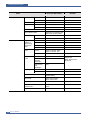
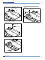
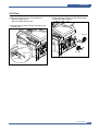
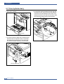
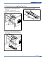
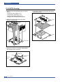
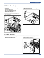
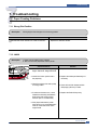
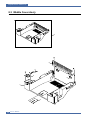
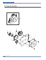
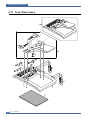
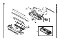
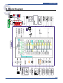
1
Dell 1815dn Service Manual 27 Mar 2006 Information in this document is subject to change without notice. 2010 Dell Inc. All rights reserved. Reproduction in any manner whatsoever without the written permission of Dell Inc.is strictly forbidden. Trademarks used in this text: Dell and the DELL logo are trademarks of Dell Inc. Other trademarks and trade names may be used in this document to refer to the entities claiming the marks and names of their products. Dell Inc. disclaims any proprietary interest in trademarks and trade names other than its own. Precautions 1 1. Precautions In order to prevent accidents and to prevent damage to the equipment please read the precautions listed below carefully before servicing the printer and follow them closely . 1.1 Safety Warning (1) Only to be serviced by appropriately qualified service engineers. High voltages and lasers inside this product are dangerous. This printer should only be serviced by a suitably trained and qualified service engineer. (2) Use only Dell replacement parts There are no user serviceable parts inside the printer . Do not make any unauthorized changes or additions to the printer, these could cause the printer to malfunction and create electric shock or fire haz-ards. (3) Laser Safety Statement The Printer is certified in the U.S. to conform to the requirements of DHHS 21 CFR, chapter 1 Subchapter J for Class 1(1) laser products, and elsewhere, it is certified as a Class I laser product con-forming to the requirements of IEC 825. Class I laser products are not considered to be hazardous. The laser system and printer are designed so there is never any human access to laser radiation above a Class I level during normal operation, user maintenance, or prescribed service condition. Warning >> Never operate or service the printer with the protective cover removed from Laser/Scanner assembly. The reflected beam, although invisible, can damage your eyes. When using this product, these basic safety pre-cautions should always be followed to reduce risk of fire, electric shock, and injury to persons. CAUTION - INVISIBLE LASER RADIATION WHEN THIS COVER OPEN. DO NOT OPEN THIS COVER. VORSICHT - UNSICHTBARE LASERSTRAHLUNG, WENN ABDECKUNG GE FFNET. NICHT DEM STRAHL AUSSETZEN. ATTENTION - RAYONNEMENT LASER INVISIBLE EN CAS D OUVERTURE. EXPOSITION DANGEREUSE AU FAISCEAU. ATTENZIONE - RADIAZIONE LASER INVISIBILE IN CASO DI APERTURA. EVITARE L ESPOSIZIONE AL FASCIO. PRECAUCION - RADIACION LASER IVISIBLE CUANDO SE ABRE. EVITAR EXPONERSE AL RAYO. ADVARSEL. - USYNLIG LASERSTR LNING VED BNING, N R SIKKERHEDSBRYDERE ER UDE AF FUNKTION. UNDG UDSAETTELSE FOR STR LNING. ADVARSEL. - USYNLIG LASERSTR LNING N R DEKSEL PNES. STIRR IKKE INN I STR LEN. UNNG EKSPONERING FOR STR LEN. VARNING - OSYNLIG LASERSTR LNING N R DENNA DEL R PPNAD OCH SP RREN R URKOPPLAD. BETRAKTA EJ STR LEN. STR LEN R FARLIG. VARO! - AVATTAESSA JA SUOJALUKITUS OHITETTAESSA OLET ALTTIINA N KYM TT M LLE LASERS TEILYLLE L KATSO S TEESEEN. Service Manual 1-1 Precautions 1.2 Caution for safety 1.2.1 Toxic material This product contains toxic materials that could cause illness if ingested. (1) If the LCD control panel is damaged it is possible for the liquid inside to leak. This liquid is toxic. Contact with the sk in should be avoided, wash any splashes from eyes or skin immediately and contact your doctor . If the liquid gets into the mouth or is swallowed see a doctor immediately. (2) Please keep toner cartridges away from children. The toner powder contained in the toner cartridge may be harmful and if swallowed you should contact a doctor. 1.2.2 Electric Shock and Fire Safety Precautions Failure to follow the following instructions could cause electric shock or potentially cause a fire. (1) Use only the correct voltage, failure to do so could damage the printer and potentially cause a fire or electric shock. (2) Use only the power cable supplied with the printer . Use of an incorrectly specified cable could cause the cable to overheat and potentially cause a fire. (3) Do not overload the power socket, this could lead to overheating of the cables inside the wall and could lead to a fire. (4) Do not allow water or other liquids to spill into the printer , this can cause electric shock. Do not allow paper clips, pins or other foreign objects to fall into the printer these could cause a short circuit leading to an electric shock or fire hazard.. (5) Never touch the plugs on either end of the power cable with wet hands, this can cause electric shock. When servicing the printer remove the power plug from the wall socket. (6) Use caution when inserting or removing the power connector . The power connector must be inserted com pletely otherwise a poor contact could cause overheating possibly leading to a fire. When removing the power connector grip it firmly and pull. (7) Take care of the power cable. Do not allow it to become twisted, bent sharply round corners or other wise damaged. Do not place objects on top of the power cable. If the power cable is damaged it could overheat and cause a fire or exposed cables could cause an electric shock. Replace a damaged power cable immediately , do not reuse or repair the damaged cable. Some chemicals can attack the coating on the power cable, weakening the cover or exposing cables causing fire and shock risks. (8) Ensure that the power sockets and plugs are not cracked or broken in any way . Any such defects should be repaired immediately. Take care not to cut or damage the power cable or plugs when moving the machine. (9) Use caution during thunder or lightening storms. Dell recommends that this machine be disconnected from the power source when such weather conditions are expected. Do not touch the machine or the power cord if it is still connected to the wall socket in these weather conditions. (10) Avoid damp or dusty areas, install the printer in a clean well ventilated location. Do not position the machine near a humidifier. Damp and dust build up inside the machine can lead to overheating and cause a fire. (11) Do not position the printer in direct sunlight. This will cause the temperature inside the printer to rise possibly leading to the printer failing to work properly and in extreme conditions could lead to a fire. (12) Do not insert any metal objects into the machine through the ventilator fan or other part of the casing, it could make contact with a high voltage conductor inside the machine and cause an electric shock. 1-2 Service Manual Precautions 1.2.3 Handling Precautions The following instructions are for your own personal safety , to avoid injury and so as not to damage the printer (1) Ensure the printer is installed on a level surface, capable of supporting its weight. Failure to do so could cause the printer to tip or fall. (2) The printer contains many rollers, gears and fans. Take great care to ensure that you do not catch your fingers, hair or clothing in any of these rotating devices. (3) Do not place any small metal objects, containers of water , chemicals or other liquids close to the printer which if spilled could get into the machine and cause damage or a shock or fire hazard. (4) Do not install the machine in areas with high dust or moisture levels, beside on open window or close to a humidifier or heater. Damage could be caused to the printer in such areas. (5) Do not place candles, burning cigarettes, etc on the printer , These could cause a fire. 1.2.4 Assembly / Disassembly Precautions Replace parts carefully, always use Dell parts. Take care to note the exact location of parts and also cable routing before dismantling any part of the machine. Ensure all parts and cables are replaced correctly . Please carry out the following procedures before dismantling the printer or replacing any parts. (1) Check the contents of the machine memory and make a note of any user settings. These will be erased if the mainboard or network card is replaced. (2) Ensure that power is disconnected before servicing or replacing any electrical parts. (3) Disconnect printer interface cables and power cables. (4) Only use approved spare parts. Ensure that part number , product name, any voltage, current or temperature rating are correct. (5) When removing or re-fitting any parts do not use excessive force, especially when fitting screws into plastic. (6) Take care not to drop any small parts into the machine. (7) Handling of the OPC Drum - The OPC Drum can be irreparably damaged if it exposed to light. Take care not to expose the OPC Drum either to direct sunlight or to fluorescent or incandescent room lighting. Exposure for as little as 5 mins can damage the surface’ s photoconductive properties and will result in print quality degradation. Take extra care when servicing the printer. Remove the OPC Drum and store it in a black bag or other lightproof container. Take care when working with the covers(especially the top cover) open as light is admitted to the OPC area and can damage the OPC Drum. - Take care not to scratch the green surface of OPC Drum Unit. If the green surface of the Drum Cartridge is scratched or touched the print quality will be compromised. Service Manual 1-3 Precautions 1.2.5 Disregarding this warning may cause bodily injury (1) Be careful with the high temperature part. The fuser unit works at a high temperature. Use caution when working on the printer . Wait for the fuser to cool down before disassembly. (2) Do not put finger or hair into the rotating parts. When operating a printer, do not put hand or hair into the rotating parts (Paper feeding entrance, motor , fan, etc.). If do, you can get harm. (3) When you move the printer. This printer weighs 17.5kg including toner cartridge and cassette. Use safe lifting and handling techniques. Use the lifting handles located on each side of the machine. Back injury could be caused if you do not lift carefully . (4) Ensure the printer is installed safely. The printer weighs 17.5Kg, ensure the printer is installed on a level surface, capable of supporting its weight. Failure to do so could cause the printer to tip or fall possibly causing personal injury or damaging the printer . (5) Do not install the printer on a sloping or unstable surface. After installation, double check that the printer is stable. 1-4 Service Manual Precautions 1.3 ESD Precautions Certain semiconductor devices can be easily damaged by static electricity . Such components are commonly called “Electrostatically Sensitive (ES) Devices”, or ESDs. Examples of typical ESDs are: integrated circuits, some field effect transistors, and semiconductor “chip” components. The techniques outlined below should be followed to help reduce the incidence of component damage caused by static electricity. Caution >>Be sure no power is applied to the chassis or circuit, and observe all other safety precautions. 1. Immediately before handling a semiconductor component or semiconductor-equipped assembly , drain of f any electrostatic charge on your body by touching a known earth ground. Alternatively, employ a commercially avail able wrist strap device, which should be removed for your personal safety reasons prior to applying power to the unit under test. 2. After removing an electrical assembly equipped with ESDs, place the assembly on a conductive surface, such as aluminum or copper foil, or conductive foam, to prevent electrostatic charge buildup in the vicinity of the assem bly. 3. Use only a grounded tip soldering iron to solder or desolder ESDs. 4. Use only an “anti-static” solder removal device. Some solder removal devices not classified as “anti-static” can generate electrical charges sufficient to damage ESDs. 5. Do not use Freon-propelled chemicals. When sprayed, these can generate electrical charges sufficient to damage ESDs. 6. Do not remove a replacement ESD from its protective packaging until immediately before installing it. Most replacement ESDs are packaged with all leads shorted together by conductive foam, aluminum foil, or a compa rable conductive material. 7. Immediately before removing the protective shorting material from the leads of a replacement ESD, touch the protective material to the chassis or circuit assembly into which the device will be installed. 8. Maintain continuous electrical contact between the ESD and the assembly into which it will be installed, until completely plugged or soldered into the circuit. 9. Minimize bodily motions when handling unpackaged replacement ESDs. Normal motions, such as the brushing together of clothing fabric and lifting one’ s foot from a carpeted floor , can generate static electricity suf ficient to damage an ESD. 1.4 Super Capacitor or Lithium Battery Precautions 1. Exercise caution when replacing a super capacitor or Lithium battery . There could be a danger of explosion and subsequent operator injury and/or equipment damage if incorrectly installed. 2. Be sure to replace the battery with the same or equivalent type recommended by the manufacturer. 3. Super capacitor or Lithium batteries contain toxic substances and should not be opened, crushed, or burned for disposal. 4. Dispose of used batteries according to the manufacture’ s instructions. Service Manual 1-5 Reference Information 2 2. Reference Information This chapter contains the tools list, list of abbreviations used in this manual, and a guide to the location space required when installing the printer . A definition of tests pages and Wireless Network information definition is also included. 2.1 Tool for Troubleshooting The following tools are recommended safe and easy troubleshooting as described in this service manual. • DVM(Digital Volt Meter) Standard : Indicates more than 3 digits. • Driver Standard : "-" type, "+" type (M3 long, M3 short, M2 long, M2 short). • Cleaning Equipments Standard : An IPA(Isopropyl Alcohol)dry wipe tissue or a gentle neutral detergent and lint-free cloth. • Vacuum Cleaner • Spring Hook Standard : For general use • Tweezers Standard : For general home use, small type. • Cotton Swab Standard : For general home use, for medical service. • Software (Driver) installation CD ROM Service Manual 2-1 Reference Information 2.2 Acronyms and Abbreviations The table in the below explains abbreviations used in this service manual. The contents of this service manual are declared with abbreviations in many parts. Please refer to the table. AC Alternating Current IC integrated circuit ADF Automatic Document Feeder IDE ASIC Application Specific Integrated Circuit Intelligent Drive electronics or Imbedded Drive Electronics ASSY assembly IEEE Institute of Electrical and Electronics Engineers. Inc IPA Isopropy Alcohol IPM Images Per Minutes LAN local area network BIOS Basic Input Output System CCD Charge Coupled Device CIS Contact Image Sensor CMOS Complementary Metal Oxide Semiconductor CN connector CON connector CPU Central Processing Unit dB decibel dbA decibelampere dBM decibel milliwatt DC direct current DCU Diagnostic Control Unit DPI Dot Per Inch DRAM Dynamic Random Access Memory DVM Digital Voltmeter ECP Enhanced Capability Port EEPROM Electronically Erasable Programmable Read Only Memory 2-2 EMI Electro Magnetic Interference EP electrophotographic EPP Enhanced Parallel Port F/W firmware GDI graphics device interface GND ground HBP Host Based Printing HDD Hard Disk Drive HV high voltage HVPS High Voltage Power Supply I/F interface I/O Input and Output Service Manual lb pound(s) LBP Laser Beam Printer LCD Liquid Crystal Display LED Light Emitting Diode LSU Laser Scanning Unit MB Megabyte MHz Megahertz NVRAM Nonvolatile random access memory OPC Organic Photo Conductor PBA Printed Board Assembly PCL Printer Command Language , Printer Control Language PDL Page Discription Language PPM Page Per Minute PTL Pre-Transfer Lamp Q’ty Quantity RAM Random Access Memory ROM Read Only Memory SCF Second Cassette Feeder SMPS Switching Mode Power Supply SPGP SEC Printer Graphic Processor SPL SEC Printer Language Spool Simultaneous Peripheral Operation Online SW Switch Sync Synchronous or synchronization USB Universal Serial Bus Reference Information 2.3 The Sample Pattern for the Test The sample pattern shown in below is the standard pattern used in the factory . The life of the toner cartridge and the printing speed are measured using the pattern shown below . (The image is 70% of the actual A4 size). 2.3.1 A4 ISO 19752 Standard Pattern This test page is reproduced at 70% of the normal A4 size Service Manual 2-3 Product Specifications 3 3. Product Specifications Specfications are correct at the time of printing. Product specifications are subject to change without notice. See below for product specifications. 3.1 Product Overview Concept: MFP of high speed Target User : Small & Medium Business Customer Benefits (Sales Points) - Fast Printing Speed (25ppm in A4 / 27ppm in Letter) - Multifunction Network Solution (Scan-to-Email, Scan-to-SMB, Scan-to-FTP) - Duplex Capability - Direct USB Connectivity 2nd Version (PDF Direct Printing) - Small Foot Print Key Features - 25 ppm Print speed/14 cpm Copy Speed - 1200 dpi Print Resolution (Addressable) - PCL6, PS3(SCX-5530FN) - 64MB System Memory/32MB DIMM(5530FN) - 50 ADF - 250 sh Paper Input / 150 sh Paper Output - 33.6 Kbps Fax Modem (5530FN only) - Duplex Print (5530FN only) Service Manual 3-1 Product Specifications 3.2 Product General Specifications Items'HOO/DVHU0)3GQ Remarks General Power Consumption Power Supply Major Features Fax, Copier, Print, Scan, ADF, Scan to USB Key Size (W*D*H) w/o Hand Set 450mmx423mmx456mm) (17.7x16.7x18") Net Weight(Inc. Toner Cartridge) 17.5kg Net Weight(exc. Toner Cartridge) 16.5kg Gross Weight(with package) 22.5kg LCD 16*2 Char I/O Interface USB2.0 (High Speed) MPU Chorus-m / 300MHz Printing Operation 450 W EPA Sleep Mode 30 W EPA Power Switch Yes Input Voltage Low Voltage : 110 ~ 127VAC High Voltage : 220 ~ 240VAC Input Frequency Noise Printing 54dBA Copy 55dBA Standby 39dBA(TBD) Warm Up Time from Cold Status Less than 42 seconds Machine Life Max. Monthly Print Volume Scan 1000pages (Duty Cycle) ADF 25000pages 1000pages Average Monthly Print Volume 1500pages Machine Life 200,000pages Periodic Replacing Pickup Roller 150,000 Pages Parts Pad Unit (Tray) 150,000 Pages Pad Unit (ADF) 20,000 Pages Transfer Roller 70,000 Pages Fuser Unit 80,000 Pages Paper Tray 150,000 Pages Environmental Temperature Humidity Altitude 3-2 50 / 60Hz(+/- 3Hz) Service Manual Operating 10~32 Non Operating -20~40 Operating 20~80% Non Operating 10~90% Max 8,200ft w/o back light System Bus 100MHz Product Specifications Items'HOO/DVHU0)3GQ Remarks DELL Laser MFP 1815 / 1815d EMI Approval Device Memory PRINT Class B Standard / Max. Duplex (Standard / Max) Program , Font (8M) + Data (2M) + Fax (4M) + Scan (6M) + Codec (4M) + N/W (8M) + Print (16M) + Scan To Email (16M) = 64MB : 64MB + 32MB / 192MB Type SDRAM Expand Memory Slot , Type SDRAM DIMM Compression Technology YES Print Speed Simplex 27ppm/Ltr, 25ppm/A4 (600 dpi) Duplex 18ipm/Ltr, 17ipm/Ltr(600dpi) Print Emulation GDI, PCL6, PCL5e PostScript Level3(Clone) Auto Emulation Sensing YES Font Type 45 Scalable, 1 Bitmap Number N/A Power Save Resolution Expand Memory specification would be defined separate note. 128MB Micron Memory will work only in GEU Burst mode off. Usable paper sizes (Let. A4. Folio.Legal), Oficio Refer to the attached file. Yes (5/10/15/30/45min.) Normal 600x600dpi (1200x1200,) RET Yes Toner Save Yes (No dedicated button on CP) Memory 16MB FPOT SCAN 64MB / 192MB(Std./Max) From Stand by Approx. 10 seconds (From LSU 'ON', A4) From Cold Status Less than 50 seconds Duplex Print 1815dn : Yes Printable Area 208 x 273 mm (Letter) Halftone(Gray Scale) 256levels Scan Method Color CCD Manual Duplex through MP tray would be possible on 1815n model. Scan Speed Linearity Approx. 15sec (USB 2.0) USB 2.0, 300dpi, Letter Size, through ADF Gray Approx. 20sec (USB 2.0) Pentium 4 2.XGHz, Color Approx. 30sec (USB 2.0) 128MB RAM Scan Speed Linearity Approx. 15sec (USB 2.0) through Platen Gray Approx. 20sec (USB 2.0) Color 75dpi/300dpi Approx. 30sec (USB 2.0) Service Manual 3-3 Product Specifications Items Dell Laser MFP 1815dn Remarks DELL Laser MFP 1815 / 1815d Resolution Optical 600*1200dpi Enhanced 4800dpi*4800dpi Halftone Scan Size 256level Max. Document Width 75, 300, 600dpi horizontal for only optical resolution Max.216mm(8.5") Effective Scan Width Max 208mm(8.2inch) COPY Scan-to Scan to Application/Network/Email/USB Key Scan To Email Locations 399 locations in the Directory with Search, Edit and Store facilities Scan Depth Color 24 bit Mono 1bit for Lineart, 8 Bit for Gray scale Text 600x300dpi Text/Photo 600x300dpi Photo 600x600dpi Other N/A Stand by Approx. 10 seconds : Platen Approx. 15 seconds : ADF From Cold Status 50 seconds Copy Speed SDMC at all mode 27cpm/Ltr, 25cpm/A4 / Letter MDSC at Text, Text/Photo (600x300dpi) 14cpm MDSC at Photo Mode (600x600dpi) 8cpm Copy Quality Selection or Original Image type selection Mode FCOT Origin Alignment Platen ADF Service Manual Center Resolution Scan:600x300dpi, 600*600dpi Print:600*600dpi Zoom Range 25% to 400% for Platen 25% to 100% for ADF Number of Copies 1~199 Preset Y 3-4 REAR LEFT es Contrast Levels 5 level Copy Mode(=Quality) Text, Text/Photo, Photo SDMC: Single Document Multiple Copy MDSC: Multi-document Single Copy Product Specifications Items Dell Laser MFP 1815dn Remarks DELL Laser MFP 1815 / 1815d COPY(Continued) TELEPHONE Collation Copy Yes Auto return to default mode Yes Changeable Default mode Contrast, Image, Reduce/Enlarge, No. of Copies Special Copy N-up copy 2-up, 4-up (ADF only) Collation Copy Yes (ADF only) Auto Fit Copy Yes(Platen only) ID Copy Yes(Platen only) Clone Yes(Platen only) Poster Yes(Platen only) Handset No On hook Dial * Yes Search * Yes(Phone Book) 1-Touch Dial * 10 Numeric Key pad (No dedicated keys) Speed Dial * 400 locations(00~399) include 1-touch dials TAD I/F Yes Tone/Pulse Selectable in Technical Mode Pause Y * Copy 2-side printed original document into one page (ex. ID Card Copy) by using Phone Book Button(Same as Rocky) Total locations can be stored es Auto Redial Yes Last Number Redial Yes Distinctive Ring Yes Caller ID No External Phone Interface Yes Report & Tx/Rx Journal Yes List Print out Confirmation Yes Help List No Auto Dial List Yes System Data List List all user setting Ring Volume Yes(Off, Low, MED, HIGH) Key Volume Yes(On, Off) Alarm Volume Yes(On, Off) Speaker Yes(On, Off, Comm. Error) Sound Control Time can be changeable; 15,30,60,180sec, Off Service Manual 3-5 Product Specifications Items Dell Laser MFP 1815dn Remarks DELL Laser MFP 1815 / 1815d Fax Compatibility ITU-T G3 Communication System Modem Speed 33.6Kbps TX Speed 3sec Color Fax Yes(Sending Only) ECM Yes Resolution Std 203*98dpi Fine 203*196dpi S.Fine 300*300dpi Scan Speed(ADF) Std Fine/S.Fine Service Manual 5 sec/ LTR Darkness, Original Type, Reduce/ Enlarge, No. Of Copies Rx fax duplex print out Yes only for 1815dn model. Multiple page scan speed 14 ppm/LTR, Std mode Receive Mode Fax, TEL, Ans/Fax, DRPD Functions LRT/MMR/CCITT No.1 Chart/33.6Kbps Compression MH/MR/MMR/JPEG 2.5 sec/ LTR Changeable Default mode Memory 3-6 PSTN/PABX Capacity 4MB Optional Memory No Max locations to store to 1 Group Dial 400 locations Fax Forward Yes(On/Off) Broadcasting up to 409 locations? Cover page Yes Delayed fax Yes Fax Forward to Email Addresses Yes (Enable / Disable), max 10 locations Memory RX Yes Voice Request No TTI Yes RTI Yes Polling No Earth/Recall No Max modem Speed Yes Auto Reduction Yes F/W Remote upgrade Yes Junk Fax barrier Yes Secure Receive Yes Memory Back-up Yes, Max. 43hours 203§x⁄98dpi, ITU-T #1(TBD) Product Specifications Items Dell Laser MFP 1815dn Remarks DELL Laser MFP 1815 / 1815d Paper Handling Paper Handling (Continued) Capacity Main Tray 250sheets (20lbs) Bypass 50 Sheets Optional Cassette 250sheets Output Capacity Face Down: 150Sheets/20lb Face Up: 1Sheet Output Control Face Up/Down controlled manually by opening rear cover Paper Size Paper Weight Paper Path Paper Size ADF Main Tray A4,Letter,Legal,Folio,Executive, B5,A4,Oficio Bypass Envelope6 3/4,7 3/4,#9, #10,DL, C5,B5, 3”x5” Main Tray 16~24 lb. Bypass 16~43 lb. Standard output Bottom to Middle Front (FIFO) Straight Through Face up, Single Sheet Max 216 x 356mm(8.5"x14") Min 76 x 127mm(3"x5") Paper Weight 12.5~28lb Capacity 50 sheets Document Size Width 142mm - 216mm(5.6" - 8.5") Document Size Length 148 mm - 356mm(5.8" - 14.0") Jam Rate Document Thickness 0.075mm - 0.13mm(0.003" - 0.005") Cassette, 2nd Feeder 1/2000 *In H/H and L/L condition, the spec. of JAM rate and Mispickup rate Double Feed is doubled. Cassette : Jam:1/1000, Double Feed:1/500 Multi-Feed Rate Printing Skew Copy Skew ADF 1/1000 Cassette, 2nd Feeder 1/1000 ADF 1/500 Top 1.5/177.8mm (1st Tray) 2.0/177.8 (2nd Tray) 2.0/177.8 (Duplex) Side 2/241.3mm (1st Tray) 2.5/241.3mm (2nd Tray) 2.5/177.8 (Duplex) Top 2.5/190mm (1st Tray) 3.0/190mm (2nd Tray) Side 3.5/277mm (1st Tray) 4.0/277mm (2nd Tray) Service Manual 3-7 Product Specifications Items Dell Laser MFP 1815dn Remarks DELL Laser MFP 1815 / 1815d Software Accessory Compatibility DOS No Win 3.x No Win 95 No Win 98 Yes Win ME Yes Win NT 4.0 Yes Win 2000 Yes Win 2003 Yes Win XP Yes Longhorn No 64 bit No Mac Yes, English only web version Linux Yes, English only WHQL MFP Yes for 2000 & XP Driver Printer GDI, PCL6, PostScript Level3(Std.) TWAIN Yes WIA Yes PSU Yes PC-FAX Yes Quick setup guide Yes Quick Reference Guide Yes Owner's manual Yes S/W CD ROM CDs for Print Driver, Scan Driver, RCP S/W Consumables FAX N/A SCAN S/W PaperPort 1 EA (3K yield ISO 19752 5% Coverage) Power Cable 1 EA Telephone Jack 1 EA Printer Cable No Type One Piece Type Toner Cartridge How to install Front door open and front loading Toner Count Service Manual PaperPort Toner Cartridge Toner 3-8 OCR Life Initial 3Kpages (5% ISO 19752Test Pattern) running Standard: 3Kpages High yield: 5 K pages Level Sensor No Yes (Dot Counter) Addition Win2003 PC fax including to network fax System Outline 4 4. System Outline This document is the product specification for Dell 1815dn. Dell 1815dn is a Multi-Function Peripheral (MFP) integrating a plain fax, a B/W laser printer , a color flatbed scanner, and a B/W copier. Dell 1815dn is developed for small workgroup and personal of fice customers. The main product concept is ° ∞High Speed and High Quality.°± This model has 27ppm print-speed, 3 sec transmission-speed for fax, 33.6kbps fax-transfer rate, optical 600 dpi color scanner, and 1200 dpi printer. Dell 1815dn is developed to meet standard approvals of FCC Part 15 Class B, FCC Part 68, IC 60950, and cUL for the US and Canada. Other markets covered are Europe, Latin America and Emerging Markets. Agency Certifications will be attained to enable launch in all target markets 4.1 System Configurations Dell 1815dn is made up of the Main Control part, Operation Panel part, Scanner part, Line interface part and Power part. Each Part is a separate Module which focuses on common and standard design of different kind of products. Main control part adopting Fax & LBP Printer exclusive Controller is composed of 1 CPU and 1 Board. Scanner part is composed of ADF and Platen and is connected with Main by Harness. Line Interface part is designed to apply TBR21 standard (Domestic, Europe, etc.) 4.1.1 CPU Part 1) CPU : ARM920T , which is exclusive controller to execute Printer & F AX Function and to execute operation block by flash memory within system program, and to control whole system. Main function block Completely Integrated System for Embedded Applications PVC - Dual / Single Beam, - LVDS Pad (VDO, HSYNC), - Support A3 1200dpi, multi-pass color. HPVC - Dual / Single Beam, - LVDS Pad (VDO, HSYNC), - Support A4 600dpi, multi-pass color. DMA - 6 Channels (if not use CIP4e, 4ch is available for external DMA. if CIP4E used (a4 DMA channel use), 2ch available for external DMA) Operation Frequency : CPU Core -> over 300MHz, System Bus -> 100MHz Operation Voltage : Core Voltage -> 1.2V, I/O Pad Voltage -> 3.3V, RTC Voltage -> 3V 2) Flash Memory : Record System Program, and download System Program by PC INTERF ACE. FAX for Journal List, and Memory for One Touch Dial, Speed Dial List. - size : 16M Byte (NOR Flash) - Access Time: 90ns (Max) - Page Access Time: 25ns (Max) Service Manual 4-1 System Outline 3) SDRAM : is used as Swath Buffer in Printing, Scan Buffer in Scanning, ECM Buffer in FAX receiving, and System Working Memory Area - size : 64Mbyte(Basic) , 96Mbyte(Duplex) 4MB : System Working Memory Area and Scan Buffer 4MB : FAX Memory Receive Area 16MB : Printing System Working Memory Area - Max Frequency : 166MHz - store Fax Receive Memory Data by using Battery 4.1.2 FAX Section Modem Part BLOCK DIAGRAM Implemented by based on Conexant DAA (Data Access Arrangement) Solution, and is roughly composed of two kinds Chip Solution - CX86710 (SFX336): Existing Modem Chip which adds SSD (System Side Device) for interfacing between LSD and DIB of FM336Plus Core - CX20493 (LSD) : LIU (Line Interface Unit) Chip which is controlled by SSD and satisfies each PSTN Requirements by modulating internal Configuration with connecting Tel Line. 4-2 Service Manual System Outline Modem (SFX336) specification. 2-wire half-duplex fax modem modes with send and receive data rates up to 33,600 bps V.17, V.34, V.29, V.27 ter, and V.21 Channel 2 Short train option in V.17 and V.27 ter PSTN session starting V.8 and V.8bis signaling HDLC support at all speeds Flag generation, 0-bit stuffing, ITU CRC-16 or CRC-32 calculation and generation Flag detection, 0-bit deletion, ITU CRC-16 or CRC-32 check sum error detection FSK flag pattern detection during high-speed receiving Tone modes and features Programmable single or dual tone generation DTMF receiver Tone detection with three programmable tone detectors Receive dynamic range: 0 dBm to 43 dBm for V.17, V.29, V.27 ter and V.21 Channel 2 9dBm to -43 dBm for V.34 half-duplex Digital speaker output to monitor received signal Two16-byte FIFO data buffers for burst data transfer with extension up to 255 bytes V.21 Channel 1Flag detect V.21 Channel 1Flag detect +3.3V only operation Typical power consumption Normal mode: 264 mW Service Manual 4-3 System Outline Signal Transition of DAA Solution Line Interface Signal of Tel Line and LSD is Analog Signal. 2) there is A/D, D/A Converter in LSD, so Analog Signal from Tel Line is converted in Digital through A/D Converter in DAA and transfer to SSD by DIB Capacitor Digital Signal from SSD is converted to Analog by D/A Converter in DAA and transfer to Tel Line Transformer transfer Clock from SSD to LSD and Clock Frequency is 4.032MHz. LSD full wave rectifies Clock to use as inner Power supply and also use as Main Clock for DIB Protocol Sync between LSD and SSD. Transformer transfer Clock by separating Primary and Secondary , and amplifies Clock Level to LSD by Coil Turns Ratio 1:1.16. Clock - Clock is supplied by transformer from SSD to LSD, and there is PWROUT to adjust output impedance of Clock CLKP SSD CLKN LSD DIBP DIBN Out Driver is inside SSD and CLKSHIGH Resistor to adjust duty of HLPWR Resistor and Clock. Clock from SSD to LSD has Dif ferential structure of 180 phase dif ference for Noise Robustness DIB Data transfer Data from SSD to LSD by Transformer, and also transfer specific data from LSD to SSD. After transferring data from SSD, RSP is transferred and LSD recognizes RSP and change LSD to output Driver transfer Data to SSD. DIB Data form SSD to LSD by Transformer has Differential structure of 180 phase dif ference between DIBP and DIBN for Noise Robustness 4-4 Service Manual System Outline 4.1.3 Line Interface Part This is Connection Part between system and PSTN(Public Switched Telephone Network), and primary circuit is usually located. Main functions are Line Interface, Telephone Connection and Line Condition Monitoring. 1 Telephone Line Connection Modular Plug : RJ-11C LIU PBA Modular Type : 623 PCB4-4 Line Code Length : 2500 50mm Line Code Color : Black ON HOOK state Characteristic 1) DC Resistance DP Dial Mode (Direct Current 30mA) : 50 ~ 300ohm DTMF Dial Mode (Direct Current 20mA) : 50 ~ 540ohm 2) Ring Sensitivity Ring detection Voltage : 40Vrms 150Vrms (condition :Current=25mA,Frequency=15Hz) product Margin : 30Vrms Ring detection Frequency : 15.3Hz 68Hz (condition : Voltage=45Vrms,Current=25mA ) product Margin : 15Hz Ring detection Current : 20mA 150Vrms 70Hz 100mA (condition : Voltage=40Vrms,Frequency=20Hz) product Margin : over 15mA 3) False Ring Sound Ring Frequency : 750 Hz + 1020 Hz Ring interrupt Cycle : On/Off depending on input Ring Signal Cycle. Service Manual 4-5 System Outline 4.1.4 Scan Part Pictorial signal input part: output signal of CCD passes through Bypass Cap change to ADC at HT82V26, and defined signal between HT82V26 and CHORUSm processes the Image signal. When AFE accept each pixel, CDS(Correlated Double Sampling ) technique which samples arm-level twice is used on each pixel by using CIP4e signal. 2) Pictorial image processing part: read CCD Pixel data in terms of 600dpi Line and process Error Diffusion Algorithm on Text mode and Photo mode, and then store Data at Scan Buf fer on PC Scan mode without algo rithm. On every mode Shading Correction and Gamma Correction are executed ahead, then processing is executed later. * Scan Image Control Specification Minimum Scan Line Time: 0.75ms Scan Resolution Scan Width : Max. 600DPI : 216mm main function - Internal 12bit ADC - White Shading Correction - Gamma Correction - CCD Interface - 256 Gray Scale 3) CCD Operating Part : CCD Image sensor use +5V and Inverter uses +24V - CCD Maximum Operating Frequency : 10MHz - CCD Line time : 0.75ms - White Data output Voltage : 0.7V 0.5V (Mono Copy, 0.75ms/line) - Maximum Inverter Current : 600 mA Max.( +24V) 4.1.5 OPE Pannel Section (1) Configuration Operations Panel uses Main Control and separated OPE Chip Micom and work as inner program, systemic operation is serial system which exchange Date with SIO Port of Main Control. OPE Panel is approxi mately composed of Micom part, Matrix part and LCD. (2) Micom controller Micom has ROM, RAM, I/O Port built-in and displays and lights LCD by CPU command of Main Control Part and report Key recognition Data to Main Control Board. 4-6 Service Manual System Outline 4.1.6 Printer Section Printer is consisted of the Engine parts and F/W , and engine parts is consisted of the mechanical parts comprising Frame, Feeding, Developing, Driving, Transferring, Fusing, Cabinet and H/W comprising the main control board, power board, operation panel, PC Interface. The main controller is consisted of ASIC (CHORUSm) parts, Memory parts, Engine Interface parts and it functions as Bus Control, I/O Handling, drivers & PC Interface by CPU. The Engine Board and the Controller Board are in one united board, and it is consisted of CPU part and print part in functional aspect. The CPU is functioned as the bus control, I/O handling, drivers, and PC interface. The main board sends the Current Image, V ideo data to the LSU and manages the conduct of Electro photography for print ing. It is consisted of the circuits of the motor (paper feed, pass) driving, clutch driving, pre-transfer lamp driving, current driving, and fan driving. The signals from the paper feed jam sensor and paper empty sensor are directly inputted to the main board. Printing Method: Laser-based Electro-photography Supported Operating Systems: Windows 98/2000/2003/NT4.0/ME/XP/ MAC (English only, no status monitor, web download only)Linux: Red Hat 8.0~9.0, Fedora Core 1~3, Mandrake 9.0~10.2, SuSE 8.2~9.2 Emulation: SPL(GDI) , PCL6, PS3,PCL5e Maximum Paper Size: Legal Effective Printing Width: Letter/Legal: Resolution: (selectable from Print Driver) Addressable 1200 x1200 dpi600x600 dpi (True; no RET) Speed: 27ppm (Letter) Input Paper Capacity: Tray: 250 sheets (20 lb) Bypass: 50 sheets (20 lb) Output Paper Capacity: 150 sheets (20 lb; sequenced 1 to N, face down) Feed Direction: Front In, Front Out (FIFO) PC Interface: USB 2.0(without HUB mode) Requires 6 ft. USB Cable (not supplied by SEC) Toner Cartridge: Toner Low Sensor: None Toner Low Indicator: Message displayed on LCD Cartridge Missing Indicator: Message displayed on LCD Paper Sensing: Tray: Add Paper message displayed on LCDBypass: Add Paper message displayed on LCD 208mmA4: 202mm Service Manual 4-7 System Outline ASIC 4-8 Items Specification Process 0.13um (STDH150) Package - 496 PBGA (total pad number:597ea) - Function pin: about 367pins - PWR & GND pin: 130pins ( (130/496) - PWR & GND pad: 204ea ((204/597) Remark 100 = 26.2 %) 100 = 34.17%) Voltage - Core Voltage: 1.2V - I/O Pad Voltage: 3.3V ?RTC Voltage : 3V CPU Core ARM 920T (I-Cache: 16KB, D-Cache-16KB) Operating Freq. - CPU Core: over 300MHz - Target System Bus: 100MHz SDRAMC - 32 Bits Only, 100MHz - 5 Banks (Up to 128MB per Bank) - Feed-back clock(for SDRAM read) is appended ROMC 4 Banks (Up to 16MB per Bank) IOC 6 Banks (Up to 16MB per Bank) DMAC 6 Channels (if not use CIP4e, 4ch is available for external DMA. if CIP4E used (a4 DMA channel use), 2ch available for external DMA) HPVC - Dual / Single Beam - LVDS Pad (VDO, HSYNC) - Support A4 600dpi, multi-pass color. PVC - Dual / Single Beam - LVDS Pad (VDO, HSYNC) - Support A3 1200dpi, multi-pass color. UART 5 Channels (Channel0 supports DMA/interrupt Operation ) INTERRUPT 6 External Interrupts, 26 Internal Interrupts TIMER 6 System Timers CIP4e -300/400/600/1200dpi CIS/CCD image sensor interface -Color/Mono grey image, Binary image scan support -600dpi Color/Mono Copy support -Image processing for High-End MFP, Digital Copier, -MH/MR/MMR CODEC function for fax - Scan image :(max) A4 1200dpi pixel processing, -Copy image :(max) A4 600dpi pixel processing NAND Flash Controller - 8/16 Bits, H/W ECC Generation - Auto Boot Mode (using internal SRAM, 4KB) MAC - 10M/100Mbps - Full IEEE 802.3 compatibility PPI IEEE1284 compliant parallel port interface GEU Graphic Execution Unit Service Manual *PWR & GND pin : 114ea*Dedicated PWR & GND pin(ring, rtc, lvds, pll): 16ea System Outline Items Specification RSH Fully Hardware Rotator/Scaler/Halftoner support Engine Controller - LSU Interface unit, contained APC function. - Step Motor: 4 Phase - PWM: 8 Channels - ADC: 8 Channels - BLDC clock support. APC DAC(2 ea) I2C Controller I2C bus(SM bus) Slave Device Support (I2C Version 2.1) RTC RTC Core Voltage: 3V PLL 2 PLL (MAIN / (H)PVC ) Remark Service Manual 4-9 System Outline 4-10 Service Manual System Outline 4.1.7 Copier Section Copy Mode: Black and White Scanner Type; CCD with Flatbed/Platen and ADF Maximum Size of Original: (max. width = 218 mm, max length =400 mm) Platen: 216 x 297 mm ADF: Legal (216 x 356 mm) Optical Resolution: 600 x 600 dpi Copy Quality - H x V: (User selectable via Content button) Text : 600 x 300 dpi (default) Text/Photo : 600 x 300 dpi Photo : 600 x 600 dpi Supported Media Types: Copy Speed: (SDMP = Single Document, Multiple Printout, MDSP = Multiple Document, Single Printout) Plain, Label, Cardstock, Transparency Platen, SDMP: 27cpm (Letter) ADF, SDMP: 27cpm (Letter) ADF, MDSP: 14cpm (Letter, Text or Text/Photo) 8cpm (Letter, Photo) Reduce/Enlarge: Platen: 25% - 400% (1% increments) ADF: 25% - 100% (1% increments) Non-printable Area: Copy Count: (Page count displayed on LCD during copy operation) 4 mm (Top, Bottom, and each Side) 1 to 199 Copy Modes: Text, Text/Photo, Photo Fixed R/E Setting: 100%, Auto-fit, 2(4)-Up Darkness Control: 5 levels First Copy Output Time (FCOT): Platen: 10 sec. (600 x 300 dpi) ADF: 15 sec. (600 x 300 dpi) Duplex Copy Automatic Duplex Copy for 1815dn model Service Manual 4-11 System Outline 4.1.8 Telephone Section Speed Dial: 400 Locations (46 digits maximum per location) On-hook Dial (manual fax): Yes Last Number Redial: Yes Automatic Redial: Yes Pause: Yes (using Redial key) Ringer Volume: Off, Low, Medium, High Tone/Pulse: Selectable (Tech Mode Only no Telecom certification for Pulse mode) 4.1.9 SMPS & HVPS SECTION The SMPS supplies DC Power to the System. It takes 110V/220V and outputs the +5V, +24V to supply the power to the main board and ADF board. The HVPS board creates the high voltage of THV/MHV/Supply/Dev and supplies it to the developer part for making best condition to dis play the image. The HVPS part takes the 24V and outputs the high voltage for THV/MHV/BIAS, and the outputted high voltage is supplied to the toner, OPC cartridge, and transfer roller. HVPS (High Voltage Power Supply) Transfer High Voltage (THV+) Input Voltage: 24 V DC 15% Output Voltage: MAX +5.0KV Duty Variable,) -1.2KV 15% () Output Voltage Trigger: 6.5 Line Regulation : under 3% (fluctuation input 21.6V ~ 27.6V) Output Voltage Rising Time 50ms Max Output Voltage Falling Time : 100 ms Max Fluctuating transfer voltage with environmental various : +650 V(Duty 10%) ~ 5 KV (Duty 90%) Environment Recognition Control Method : The THV-PWM ACTIVE is transfer active signal. It detects the resistance by recognizing the voltage value, F/B, while permits the environmental recognition voltage. Output Voltage Control Method : Transfer Output Voltage is outputted and controlled by changing Duty of THVPWM Signal. 10% Duty : +650V, 90% Duty : +5KV 4-12 Service Manual System Outline Charge Voltage (MHV) Input Voltage : 24 V DC 15% Output Voltage : -1.2KV ~ -1.8KV DC 3% Output Voltage Rising Time : 50 ms Max Output Voltage Falling Time : 50 ms Max Output Control Signal(MHV-PWM) : CPU is HV output when PWM is Low Cleaning Voltage (THV-) The (+) Transfer Voltage is not outputted because the THV PWM is controlled with high. The (-) Transfer Voltage is outputted because the THV-Enable Signal is controlled with low The output fluctuation range is big because there is no Feedback control. Developing Voltage (DEV) Input Voltage : 24 V DC 15% Output Voltage: -200V ~ -600V DC 3% Output Voltage Fluctuation Method : PWM Control Line Regulation : under 3% (fluctuation input 21.6V ~ 27.6V) Load Regulation : Under 3% Output Voltage Rising Time : 50 ms Max Output Voltage Falling Time : 50 ms Max Output Control Signal (BIAS-PWM) : the CPU output is HV output when PWM is low . Supply Output Voltage : -300V ~ -800V DC 5% (ZENER using, DEV ) Line Regulation : under 3% (fluctuation input 21.6V ~ 27.6V) Load Regulation : Under 3% Output Voltage Rising Time : 50 ms Max Output Voltage Falling Time : 50 ms Max Output Control Signal (BIAS-PWM) : the CPU is HV output when PWM is low . Service Manual 4-13 System Outline SMPS (Switching Mode Power Supply) It is the power source of entire system. It is assembled by an independent module, so it is possible to use for common use. It is mounted at the bottom of the set. It is consisted of the AMPS part, which supplies the DC power for driving the system, and the AC heater control part, which supplies the power to fuser. SMPS has two output channels. Which are 3.3V and +24V . AC Input Input Rated Voltage: AC 115V ~ 127V / AC 220V ~ 240V AC 120V / AC 220V(EXP version) Input Voltage fluctuating range : AC 198V ~ 264V AC 90V ~ 135V / AC 198V ~ 264V (EXP version) Rated Frequency : 50/60 Hz Frequency Fluctuating range : 47 ~ 63 Hz Input Current : Under 5.0Arms / 2.5Arms (But, the status when lamp is of f or rated voltage is inputted/ outputted ) Rated Output Power NO ITEM CH1 CH2 1 CHANNEL NAME +5V +24.0V 2 CONNECTOR PIN CON 3 5V PIN: 11,13,15 GND PIN: 12,14,16 CON 3 24V PIN:3,5,7,9 GND PIN:4,6,8,10 3 Rated Output +5V 5% (4.75 5.25V) +24V 10% (21.6 26.4V) 4 Max. Output Current 3A 4.4 A 5 Peak Loading Current 3.6 A 5.3 A 6 RIPPLE NOISE Voltage 100mVp-p Under 500mVp-p 7 Maximum output 15W 105.6W 8 Peak output 18W 127.2W 9 Protection for loading shortage and overflowing current Shut down or Fuse Protection Shut down or Output Voltage Drop Remark 1ms 1ms Consumption Power 4-14 NO ITEM CH2(+5V) CH3(+24V) System 1 Stand-By TBD A TBD A AVG : TBD Wh 2 PRINTING TBD A TBD A AVG TBD Wh 3 Sleep-Mode TBD A TBD A AVG : TBD Wh Service Manual System Outline Length of Power Cord : 1830 50mm Power Switch : Use Feature Insulating Resistance : 100 or more (at DC 500V) Withstanding Voltage : Must be no problem within 1 min. (at 1000V -LV model / 1500Vac-HV model,10mA) Leaking Current : under 3.5mA Running Current : under 40A PEAK (AT 25 , COLD START) under 60A PEAK (In other conditions) Rising Time : within 2Sec Falling Time : over 20ms Surge : Bi-Wave 3kV ? Normal, 6KV - Common Environment Condition Operating temperature range : 0 Maintaining temperature range : -25 Preserving Humidity Condition : 30% 40 85 90% RH Operating atmospheric pressure range : 1atm EMI Requirement : CISPR ,FCC, CE, MIC Safety Requrement :IEC950 UL1950, CSA950, C-UL,NOM,TUV,Semko,EK,CB, GOST, EPA, Power save FUSER AC POWER CONTROL Fuser(HEAT LAMP) gets heat from AC power. The AV power controls the switch with the Triac, a semiconductor switch. The ON/OFF control is operated when the gate of the Triac is turned on/off by Phototriac (insulting part). In other words, the AC control part is passive circuit, so it turns the heater on/of f with taking signal from engine control part. When the HEATER ON signal is turned on at engine, the LED of PC501 (Photo Triac) takes the voltage and flashes. From the flashing light, the Triac part (light receiving part) takes the voltage, and the voltage is supplied to the gate of Triac and flows into the Triac. As a result, the AC current flows in the heat lamp, and heat is occurred. On the other hand, when the signal is of f, the PC501 is off, the voltage is cut off at the gate of Triac, the Triac becomes off, and then the heat lamp is turned of f. Triac (Q501) feature : 24A-LV model / 16A-HV model, 600V SWITCHING Phototriac Coupler (PC501) Turn On If Current : 15mA 50mA(Design: 16mA) High Repetive Peak Off State Voltage : Min 600V Service Manual 4-15 System Outline 4.1.10 Toner Cartridge In the toner cartridge, the OPC unit and the developer unit are in a body . The OPC unit has OPC drum and charging roller , and the developer unit has toner, toner cartridge, supply roller, developing roller, and the blade. 4.1.11 LSU (Laser Scanner Unit) The LSU unit is controlled by video controller. It scans the video data received from video controller with laser beam by using the rotation principle of the polygon mirror to create the latent image on the OPC drum. It is the core part of LBP . The OPC drum rotates as the same speed as the paper feeding speed. It creates the /HSYNC signal and sends it to the engine when the laser beam of the LSU reaches the end of the polygon mirror , and the engine detects the /HSYNC sig nal to arrange the vertical line of the image on the paper . After detecting the /HSYNC signal, the image data is sent to the LSU to arrange the its margin on the paper . The one side of the polygon mirror is one line for scanning. 4.1.12 Fixing Part (FUSER) The fuser is consisted of the Heat Lamp, Heat Roller , Pressure Roller, Thermistor and Thermostat. It adheres the toner to the paper with pressure and a heat to complete the printing job. 4.1.13 TRANSFER Ass’y It is consisted of PTL (pre-transfer lamp) and Transfer Roller. The PTL sends a light to the OPC drum, makes the current on the drum surface to low, and improve the transfer efficiency. The transfer roller delivers the toner of the OPC drum to the paper . 4.1.14 Driver Ass’y It is a power delivery unit by gearing: BLDC Motor(P62) -> Pickup/Feeder/Developer STEP Motor( 55) -> Feeder/Exit STEP Motor( 42) -> Duplex 4-16 Service Manual System Outline 4.1.15 Feeding Part Feeding Type: Universal Cassette Type Feeding Standard: Center Loading Feeding Qty: Cassette 250 sheets (75g/ , 20lb paper standard) Bypass 50 sheet (Paper, OHP, Envelope etc.) Separating Type: Cassette - Friction Pad Type Bypass - Friction Pad Type Driver Type: Driving by Gearing from Main Motor Pick_up Roller Driver: Solenoid 4.1.16 Duty Cycle (except where noted otherwise, all toner usage references are for Letter size paper at 5% coverage) Product Life Time : 200,000 images or 5 years, whichever comes first Toner CRU: Initial CRU to be 3,000 pages (In-Box): 85 grams After-market CRU will be 5,000 pages: 140grams Recommended Duty Cycle: 1,500 pages/month (A4 size ,ISO 19752 5% coverage) AMPV: Printing: 2,500 pages Flat-bed: 150 pages ADF: 150 pages Max. Monthly Volume: Printing: 25,000 pages Flat-bed: 1,000 pages ADF: 1,000 pages Periodic replace parts are recommended as follows: CRU ADF Rubber Pad: 20,000 pages ADF Pickup Roller: 80,000pages Pick-up Roller (Paper Tray): 150,000 pages Fuser Door: non periodic Transfer Roller: 70,000 pages Fuser Unit : 80,000 pages Service Manual 4-17 Precautions 5 5. Disassembly and Reassembly 5.1 General Precautions on Disassembly When you disassemble and reassemble components, you must use extreme caution. The close proximity of cables to moving parts makes proper routing a must. If components are removed, any cables disturbed by the procedure must be restored as close as possible to their original positions. Before removing any component from the machine, note the cable routing that will be af fected. Releasing Plastic Latches Many of the parts are held in place with plastic latches. The latches break easily; release them carefully. To remove such parts, press the hook end of the latch away from the part to which it is latched. Whenever servicing the machine, you must perform as follows: 1. Check to verify that documents are not stored in memory. 2. Be sure to remove the toner cartridge before you disassemble parts. 3. Unplug the power cord. 4. Use a flat and clean surface. 5. Replace only with authorized components. 6. Do not force plastic-material components. 7. Make sure all components are in their proper position. Service Manual 5-1 Precautions 5.2 Front Cover 1. Take out the Cassette. 3. If necessary, remove the Toner Cartridge. Toner Cartridge Cassette 2. Open the Cover. 4. To remove the Front Cover, first pull the part below the both side of the Front Cover with a light pressure to the direction of arrow. 2 1 Front Cover 5-2 Service Manual Precautions 5.3 MP Tray Ass'y 1. Open the MP Tray Ass'y 3. Apply light pressure to the both side of the MP Tray Ass'y and pull it in the direction of arrow , as shown below. MP Tray Ass'y 2. Pull the Tray Links from the both side of the Front Cover with a light pressure to the direction of arrow . MP Tray Ass'y Tray Link Service Manual 5-3 Precautions 5.4 Rear Cover 1. Open the DIMM Cover from the Left Side Cover in the direction of arrow, as shown below. 3. Remove the four screws securing the Rear Cover and then Release the Rear Cover from the Set. Rear Cover 2 1 DIMM Cover 4. To remove the Face Up Cover, first release the Stopper Strap in the direction of arrow. 2. Take out the Duplex Unit. 1 Duplex Unit Stopper Strap 5-4 Service Manual 2 Precautions 5. Unlatch the Face Up Cover from the Rear Cover and then release the Face Up Cover, as shown below. Face Up Cover Service Manual 5-5 Precautions 5.5 Fuser Ass'y 1. Before you remove the Fuser Ass'y, you should remove: - Rear Cover (Refer to 5.4) 2. Remove the four screws securing the Fuser Ass'y and then pull the Fuser Ass'y. 4. To remove the Halogen Lamp, first release REC Harness from the left side of the Halogen Lamp and then release the CON Harness from the right side of the Halogen Lamp, as shown below. Fuser Ass'y REC Harness CON Harness 3. Release the CON Harness and REC Harness from the Thermostat and then remove the three screws securing the Thermostat and remove it. 5. Remove the two screws securing the both side of the Halogen Lamp and then release in the direction of arrow, as shown below. REC Harness Thermostat CON Harness Halogen Lamp 5-6 Service Manual Precautions 6. Remove the two screws securing the IInput Guide and remove it. 8. Remove the three screws securing the Idle Gear Bracket and remove it. Idle Gear Bracket Input Guide 9. Remove the one screw securing the Fuser Cover and release the Fuser Cover from the Fuser Frame. 7. Unplug the connector from the Input Guide and remove the one screw securing the Thermistor and remove it. Fuser Cover Thermister Fuser Frame Service Manual 5-7 Precautions 10. Release the Fuser Gear and HR Bush and then remove the Heat Roller, as shown below. 11. Remove the Jam Link Lever (L,R) and Jam Holder (L,R) and then remove the Pressure Roller, as shown below. Jam Link Lever Heat Roller HR Bush Jam Holder HR Bush Fuser Gear Jam Link Lever Jam Holder 5-8 Service Manual Precautions 5.6 Side Cover (Left, Right) 1. Before you remove the Side Cover (Left, Right), you should remove: - Rear Cover (Refer to 5.4) 4. Remove the two screws securing the Left Side Cover , as shown below. 2. Remove the two screws securing the Right Side Cover, as shown below. 5. Apply light pressure to the bottom of the Left Side Cover and pull it to the left side in the direction of arrows, as shown below. 3. Apply light pressure to the bottom of the Right Side Cover and pull it to the right side in the direction of arrows, as shown below. Left Side Cover Right Side Cover Service Manual 5-9 Precautions 6. To remove the DIMM Cover, first open the DIMM Cover (refer to 5.4.1) and then release the DIMM Cover, as shown below. DIMM Cover Notice : Be careful not to damage the hooks when remove the Side Cover (Left, Right). 5-10 Service Manual Precautions 5.7 Scanner Ass'y 1. Before you remove the Scanner Ass'y, you should remove: - Rear Cover (Refer to 5.4) - Side Cover (Left, Right) (Refer to 5.6) 4. Pull up the Scanner Ass'y, as shown below. Scanner Ass'y 2. Remove the two screws securing the Scanner Ass'y, as shown below. 5. Release the ADF Harness from the underneath the Scanner Ass'y. 3. Remove the one screw securing the Ground Cable and unplug the four connectors and CCD Cable. ADF Ground Cable ADF Harness Service Manual 5-11 Precautions 6. Lift the ADF Ass'y upward to remove it. 9. Remove the four screws securing the Scan Upper . ADF Ass'y Scanner 7. To remove the OPE Unit, first pull the part below the front of the OPE Unit with a light pressure to the direction of arrow. 10. Release the four hooks securing the Scan Upper to the Scan Lower and remove it, as shown below . Scan Upper OPE Unit Scan Lower 11. Remove the CCD Cable, as shown below. 8. Unplug the three connectors from the OPE PBA, as shown below and then release the Battery. OPE Unit Battery 5-12 Service Manual CCD Cable Precautions 12. Pull up the CCD Shaft and take out the CCDM. 15. If necessary, remove the two screws securing the Scan Motor and remove it, as shown below. CCDM CCD Shaft Gear Bracket Ass'y Scan Motor 13. Squeeze the spring to release the tension in the Belt and lift from the pulleys, as shown below. Belt Spring Caution : Reassembling CCDM 1) When refitting the Scanner Belt and Belt Spring take care to relocate the tension spring as close to the right side of the CCDM as is possible, as shown below. 2) When refitting the Scan Upper Cover take care to ensure that the Cover Open Switch is not trapped. 14. Remove the three screws securing the Scan Motor Ass'y and remove it. Scan Motor Ass'y Service Manual 5-13 Precautions 16. Unplug the connector from the Open Sensor Ass'y. 19. Unplug the Harness from the CCD Home Sensor and release the CCD Home Sensor, as shown below. CCD Home Sensor Harness 17. Unlatch the Open Sensor and remove it, as shown below. Sensor Lever Open Sensor 18. Remove the CCD Holder. CCD Holder 5-14 Service Manual Precautions 5.8 ADF Ass'y 1. Before you remove the ADF Ass'y, you should remove: - Rear Cover (Refer to 5.4) - Side Cover (Left, Right) (Refer to 5.6) - Scanner Ass'y (Refer to 5.7) 4. Remove the Open Cover, as shown below. Open Cover 2. Release the ADF Harness from the underneath the Platen Cover Ass'y. 2 1 2 ADF Harness Platen Cover Ass'y 3. Remove the two screws securing the ADF Engine Ass'y and remove it. Notice : When working on the ADF Motor Ass'y take care not to contaminate any of the rubber surfaces with grease. 5. Release the Bush and rotate it until it reaches the slot, as shown below. Then lift the Pick Up Ass'y out. ADF Engine Ass’y Pick Up Ass'y 1 Bushing 2 Notice : Take care to thread the ADF Harness through the Platen Cover Ass'y. Service Manual 5-15 Precautions 6. Remo the two screws securing the ADF Upper and remove it, as shown below. 7. Unplug the one connector and remove four screws securing the ADF Motor Ass'y and then remove the one screw securing the Ground Cable, as shown below. Then take out the ADF Motor Ass'y. ADF Motor Ass'y ADF Upper Notice : Before removing the ADF Engine Ass'y take great care to note the position of the Ferrite Core and the Motor Harness routing. When refitting the ADF Engine Ass'y ensure that the Harness and Ferrite are properly located and are clear of the Motor Fan and White Bar Clip. 5-16 Service Manual ADF Lower Precautions 5.9 OPE Unit 1. Before you remove the OPE Unit, you should remove: - Rear Cover (Refer to 5.4) - Side Cover (Left, Right) (Refer to 5.6) - Scanner Ass'y (Refer to 5.7) 4. Remove the Keys from the OPE Cover. 2. Remove the five screws securing the OPE PBA from to the OPE Cover. OPE Cover Select Key Menu Key Tel Key OPE PBA 3. Remove the Contact Rubber from the OPE Cover . Contact Rubber Service Manual 5-17 Precautions 5.10 Shield Controller Ass'y 1. Before you remove the Shield Controller Ass'y, you should remove: - Rear Cover (Refer to 5.4) - Side Cover Left (Refer to 5.6.4) 4. Remove the three screws securing the Main PBA to the Bracket and unplug the Film Cable and then remove the Main PBA. 2. Unplug the all connectors and remove the one screw securing the Ground Cable. Main PBA Film Cable Shield 5. The connectors are located, as shown below. Flat Cover ADF CCD Flat Motor 3. Remove the five screws securing the Shield Controller Ass'y and remove it. OPE Panel USB Host Cartridge LSU_5V Shield Controller Ass'y LSU Thermo MPF_SEN USB MPF REGI Pick Up Line Network BLDG USB Engine Tray2 Duplex Motor Modem PBA 5-18 Service Manual Precautions 6. Remove the three screws securing the Modem PBA to the Bracket and unplug the Film Cable and then remove the Modem PBA. 7. Remove the two screws securing the Speaker to the Bracket and unplug the connector from the Modem PBA and then remove the Speaker. Film Cable Shield Modem PBA Shield Speaker Service Manual 5-19 Precautions 5.11 Drive Ass'y 1. Before you remove the Drive Ass'y, you should remove: - Rear Cover (Refer to 5.4) - Side Cover Left (Refer to 5.6.4) - Shield Controller Ass'y (Refer to 5.10) 3. If necessary, remove the four screws securing the BVDC Motor Ass'y and remove it. Gear Bracket Ass’y 2. Remove the five screws securing the Drive Ass'y and remove it. Drive Ass'y Harness Notice : The six screws have numbers stamped into the Drive Ass'y base plate. When refitting the Drive Ass'y tighten the screws the order they are numbered. Only screws numbered 1 to 5 are fitted at this stage. Screw 6 is fitted when the Shield Controller Ass'y is refitted. 5-20 Service Manual BVDC Motor Ass’y Precautions 5.12 Duplex Drive Ass'y 1. Before you remove the Duplex Drive Ass'y, you should remove: - Rear Cover (Refer to 5.4) - Side Cover Right (Refer to 5.6.3) 3. If necessary, remove the two screws securing the Duplex Motor and remove it. 2. Unplug the connector from the Connection PCB and remove the three screws securing the Duplex Drive Unit and remove it. Harness Duplex Motor Bracket Ass'y Connection PCB Duplex Motor Duplex Drive Ass'y Service Manual 5-21 Precautions 5.13 Shield SMPS Ass'y 1. Before you remove the Shield SMPS Ass'y, you should remove: - Rear Cover (Refer to 5.4) - Side Cover Right (Refer to 5.6.3) - Duplex Drive Ass'y (Refer to 5.12) 4. Unplug the connector (AC Inlet) and remove the four screws securing SMPS and remove it. Shield SMPS (With AC Inlet) 2. Unplug the two connectors (HVPS, Fuser). AC Inlet Connector Insulator Sheet Fuser Connector HVPS Connector 3. Remove the three screws securing the Shield SMPS Ass'y and remove it. Shield SMPS Ass'y 5-22 Service Manual SMPS Precautions 5.14 Connection PCB 1. Before you remove the Connection PCB, you should remove: - Rear Cover (Refer to 5.4) - Side Cover Right (Refer to 5.6.3) 4. The connectors are located, as shown below. FAN Duplex Exit Motor 2. Unplug the all connectors. Duplex Motor Fan Main HVPS Connection PCB 3. Remove the two screws securing the Connection PCB and remove it. Connection PCB Service Manual 5-23 Precautions 5.15 Fuser Drive Ass'y 1. Before you remove the Fuser Drive Ass'y, you should remove: - Rear Cover (Refer to 5.4) - Side Cover Right (Refer to 5.6.3) 4. If necnsary, remove the two screws securing the Step Motor and remove it. Fuser Exit Bracket Ass'y 2. Unplug the connector from the Connection PCB. Step Motor Harness Connection PCB Fuser Drive 3. Remove the three screws securing the Fuser Drive Ass'y and remove it. Fuser Drive Ass'y 5-24 Service Manual Precautions 5.16 Fan 1. Before you remove the Fan, you should remove: - Rear Cover (Refer to 5.4) - Side Cover Right (Refer to 5.6.3) 3. Remove the two screws securing the Fans and then pull the Fans (Main, Duplex). 2. Unplug the two connectors from the Connection PCB, as shown below. Duplex Fan Connection PCB Duplex Fan Main Fan Main Fan Service Manual 5-25 Precautions 5.17 Pick Up Roller Ass'y 1. Take out the Cassette. 3. To remove the Shaft, first release the locker and slide the Shaft from left to right, then lift the notch attached to the Cam so that it's released from the Shaft. Then release the Bush from the Shaft and remove the Shaft from the Duplex Guide Housing, as shown below. 2 3 Shaft Cam Bush 1 Cassette Locker 2. To remove the Pick Up Roller Ass'y, first lift the notch attached to the Pick Up Roller Ass'y from the Shaft, then slide the Pick Up Roller Ass'y from left to right and it will be released completely, as shown below. 2 1 Pick Up Roller Ass'y 5-26 Service Manual 4 Precautions 5.18 Duplex Guide Housing (With Feed Roller) 1. Before you remove the Duplex Guide Housing, you should remove: - Pick Up Roller Ass'y (Refer to 5.17) 4. Pull the Feed Roller from the Bushing. 2. Remove the two screws securing the Duplex Guide Housing. Feed Roller Bushing Duplex Guide Housing 3. Unplug the one connector (Photo Interrupter) and remove the Duplex Guide Housing (with Feed Roller), as shown below. Photo Interrupter Connector Duplex Guide Housing Service Manual 5-27 Precautions 5.19 HVPS Housing 1. Before you remove the HVPS Housing, you should remove: - Duplex Drive Ass’y (Refer to 5.12) - Pick Up Roller Ass'y (Refer to 5.17) - Duplex Guide Housing (Refer to 5.18) - Unplug the two Connectors (HVPS) (p5-22) 2. Remove the eight screws securing the HVPS Housing, as shown below. 4. If necessary, remove the three screws securing the HVPS and remove it. HVPS Insulator Sheet Shield HVPS Housing 3. Unplug the connector for connection PBA & SMPS first. Unplug the other connectors. Duplex Motor Engine Duplex Guide Housing 5-28 Service Manual Connection PBA & SMPS Precautions 5.20 Middle Cover Ass'y 1. Before you remove the Middle Cover Ass'y, you should remove: - Rear Cover (Refer to 5.4) - Side Cover (Left, Right) (Refer to 5.6) - Scanner Ass'y (Refer to 5.7) - Shield Controller Ass'y (Refer to 5.10) 2. Remove the six screws securing the Middle Cover Ass'y and remove it. 3. If necessary, remove the two screws securing the USB Host PBA and remove it. Harness USB Host PBA Middle Cover Ass'y 5.21 Cover Mid Front 1. Before you remove the Cover Mid Front, you should remove: - Middle Cover Ass'y (Refer to 5.20) 2. Remove the four screws securing the Cover Mid Front and release two hooks in the center. This cover is fragile take care when removing it. Hook Hook Cover Mid Front Service Manual 5-29 Precautions 5.22 MPF Housing 1. Before you remove the MPF Housing, you should remove: - Cover Mid Front (Refer to 5.21) 2. Remove the four screws securing the MPF Housing and remove it. 3. To remove the MP Pick Up Ass'y, first lift the notch attached to the left side Stopper so that it's slide the right to left from the Shaft, then left side Idle slid the right to left from the Shaft and take out the MP Pick Up Ass'y, as shown below. MPF Housing Stopper 1 MPF Housing 5-30 Service Manual MP Pick Up Ass'y 2 Idle Precautions 5.23 Feed Roller Parts 1. Before you remove the Feed Roller Parts, you should remove: - Pick Up Roller Ass'y (Refer to 5.17) - Duplex Guide Housing (Refer to 5.18) - Middle Cover Ass'y (Refer to 5.20) - MPF Housing (Refer to 5.22) 4. Release the E-Ring securing the Feed2 Gear and remove it. 2. Remove the two screws securing the both side of the Guide Paper and then remove the Guides. E-Ring Guide Paper Feed2 Gear 5. Remove the three screws securing the Feed Bracket Unit and then remove the Feed Bracket Unit and Feed2 Shaft. Feed Bracket Unit 3. Pull up the Feed Idle Shaft and the Bushs (with Spring). Feed Idle Shaft Srring Bush Feed2 Shaft Service Manual 5-31 Precautions 6. If necessary, release the three E-Rings securing the Gears (T2 Idle, Retard, Idle) and then remove the Gears from the Feed Bracket, as shown below. 8. Pull up the Feed1 Roller from the Bushing, as shown below. Idle Gear Bracket E-Ring Retard Gear T2 Idle Gear Notice : Be aware of the E-Rings to ensure they are not lost. 7. Remove the Clutch Unit, as shown below. Clutch Unit Feed1 Gear Ass'y Feed Shaft 5-32 Service Manual Feed1 Roller Precautions 5.24 Pick Up Gear Ass'y & Solenoids 1. Before you remove the Pick Up Gear Ass'y & Solenoids, you should remove: - Duplex Guide Housing (Refer to 5.18) - Feed Bracket Unit (Refer to 5.23.5) 3. Remove the two screws securing the Manual Solenoid and Feed Solenoid and then remove the Solenoids, as shown below. 2. Release the Pick Up Gear Ass'y and Pick Up Gear Shaft, as shown below. Feed Solenoid Pick Up Gear Ass'y Pick Up Gear Shaft Manual Solenoid 5.25 Exit Roller 1. Before you remove the Exit Roller, you should remove: - Fuser Drive Ass'y (Refer to 5.15) - Middle Cover Ass'y (Refer to 5.20) 2. Remove the Exit Gear, and release the Bearing at one end then remove the Roller Exit F/Down and Exit Roller Rack, as shown below. Bearing Exit Roller Rack Roller Exit F/Down 1 1 Exit Gear 2 Service Manual 5-33 Precautions 5.26 LSU 1. Before you remove the LSU, you should remove: - Middle Cover Ass'y (Refer to 5.20) 2. Remove the four screws securing the LSU and remove it. LSU 5.27 Terminal PBA 1. Before you remove the CRUM2 PBA, you should remove: - Middle Cover Ass'y (Refer to 5.20) - LSU (Refer to 5.26) 2. Remove the one screw securing the CRUM2 PBA and remove it and then release the four Terminals, as shown below. Terminal PBA Terminal Notice : Be aware of the Terminals to ensure they are not lost. 5-34 Service Manual Precautions 5.28 Transfer Roller Parts 1. To remove the Transfer Roller, first push the TR Holder and then take out the Transfer Roller, as shown below. Transfer Roller 2 1 TR Holder Notice : Do not grab the rubber part of the Transfer Roller, it may cause a malfunction due to a foreigen object. Hole the both side of the Transfer Roller when replacing it. Service Manual 5-35 Alignment & Adjustments 6 6. Alignment and Adjustments This chapter describes the main functions for service, such as the product maintenance method, the test output related to maintenance and repair , DCU using method, Jam removing method, and so on. It includes the contents of manual. 6.1 Paper path Scanner Part Roller-Pickup Roller-ADF Roller-Exit Roller-Feed Engine Part Roller-Exit Roller-Heat Duplex Roller-REGI Roller-MP OPC Roller-Transfer Roller-Pressure Roller-Feed Roller-Pickup Service Manual 6-1 Alignment & Adjustments 6.2 Clearing Paper Jams Occasionally, paper can be jammed during a print job. Some of the causes include: • The tray is loaded improperly or overfilled. • The tray has been pulled out during a print job. • The front cover has been opened during a print job. • Paper was used that does not meet paper specifications. • Paper that is outside of the supported size range was used. If a paper jam occurs, LCD window will show it’ s speeds. Find and remove the jammed paper. If you don’t see the paper, open the covers. Do not use a pinset or a sharp metal tool when removing a jam. The covering of a metal part can be removed which can cause an electric leakage. 6-2 Service Manual Alignment & Adjustments 6.2.1 Clearing Document Jams When a document jams while it passes through the ADF, Document Jam appears on the display. NOTE: To prevent document jams, use the document glass for thick, thin or mixed documents. 1. Remove the remaining documents from the ADF. If the document is jammed in the paper feed area: a. Open the ADF cover. c. Close the ADF cover. Then reload the document into the ADF. b. Remove the document by gently pulling it out. Service Manual 6-3 Alignment & Adjustments If the document is jammed in the paper exit area: a. Open the document cover and turn the release knob to remove the misfed documents from the document document output tray. b. Close the document cover. Then load the documents back into the ADF. 6-4 Service Manual 2. If you cannot see the paper or the paper does not move when you pulled, open the document cover. 3. Turn the release knob so that you can easily seize the misfed document, and remove the document from the roller or the feed area by carefully pulling it gently to the right. 4. Close the document cover. Then load the documents back into the ADF. Alignment & Adjustments 6.2.2 Clearing Jams in the Paper Paths When a paper jam occurs, Paper Jam appears on the display . Refer to the table below to locate and clear the paper jam. Operator Panel Message Location of Jam Go to Paper Jam 0 Open Front Door Paper Feed Jam (tray 1) Paper Feed Jam (optional tray 2) "Paper Feed Jam (tray 1)" or "Paper Feed Jam (optional tray 2)". Paper Jam 1 Cartridge Area Fuser Area Jam "Fuser Area Jam". Paper Jam 2 Open Rear Door Paper Exit Jam "Paper Exit Jam". Duplex Jam 0 Check Inside a in the duplex unit "Duplex Jam 0". Duplex Jam 1 Check Inside a between the duplex unit and fuser area "Duplex Jam 1". To avoid tearing the paper, pull the jammed paper out gently and slowly. Follow the steps below to clear the jam. 6.2.3 Paper Feed Jam (tray 1) 1. Open and close the front cover. The jammed paper automatically exits the printer. If the paper does not exit, go to the next step. 3. Remove the paper by gently pulling it straight out. 2. Pull the paper tray open. If you cannot see the paper or the paper does not move when pulled, check the fuser area. For more information, see "Fuser Area Jam". 4. Insert the paper tray into the printer until it snaps into place. Printing automatically resumes. Service Manual 6-5 Alignment & Adjustments 6.2.4 Paper Feed Jam (optional tray 2) 1. Pull the optional tray 2 open. 3. Pull the tray 1 half. 2. Remove the jammed paper from the printer. 4. Pull the paper straight up and out. If you cannot see the paper in this area or the paper does not move when pulled, go to the next step. 6.2.5 Bypass tray Jam 1. If the paper is not feeding properly, pull the paper out of the printer. 6-6 Service Manual 2. Open and close the front cover to resume printing. Alignment & Adjustments 6.2.6 Fuser Area Jam NOTICE: The fuser area is hot. Take care when removing paper from the printer. 2. Remove the paper by gently pulling it straight out. 1. Open the front cover and lightly pull the toner cartridge straight out. 3. Replace the toner cartridge and close the front cover . Printing automatically resumes. 6.2.7 Paper Exit Jam 1. Open and close the front cover. The jammed paper automatically exits the printer. If the paper does not exit, go to the next step. 3. If you cannot see the paper in the output tray or the paper does not move when pulled, open the rear cover. 2. Gently pull the paper out of the output tray . 4. If you see the jammed paper, push the two blue pressure levers up and remove the paper. If you do not see the paper, go to the next step. Service Manual 6-7 Alignment & Adjustments 5. Release the blue strap, the rear cover stopper , and fully open the rear cover, as shown. 8. Pull the jammed paper out. If the jammed paper does not move when you pull, push the two blue pressure levers up to loosen the paper, and then remove it. 6. Unfold the duplex guide fully. 9. Return the levers, fuser door, rear cover stopper, and duplex guide to their original position. 10. Close the rear cover. Printing automatically resumes. 7. While pushing the fuser lever to the right, open the fuser door. NOTE: Make sure to unfold the fuser guide before opening the fuser door or you may damage the fuser door. 6-8 Service Manual Alignment & Adjustments 6.2.8 Duplex Jam 0 1. Pull the duplex unit out of the printer . If the paper does not come out with the duplex unit, remove the paper from the bottom of the printer . 2. Remove the jammed paper from the duplex unit. 3. Push the duplex unit to the printer. CAUTION: If you do not push the duplex unit in correctly, a paper jam may occur. Service Manual 6-9 Alignment & Adjustments 6.2.9 Duplex Jam 1 1. Open the rear cover. 3. Pull the jammed paper out. 2. Unfold the duplex guide fully. 4. Return the duplex guide and close the rear cover . Printing automatically resumes. 6-10 Service Manual Alignment & Adjustments 6.3 User Mode(Dell Laser MFP1815dn) The table in the bellow explains the possible setting functions by user . The details about the ways to use are explained in the user manual. In the service manual, the items are about the possible set-up by user . 1.Paper Setting Paper Tray Paper Size 4.Fax Feature Delay Fax Priority Fax Add / Cancel 7.Sound/Volume Speaker Ringer Key Sound Alarm sound 2.Copy Setup Change Default Timeout 5.Advanced Fax 3.Fax Setup Receive Mode Ring to Answer Contrast Redial Term Redials MSG Confirm. Auto Report Auto Reduction Discard Size 6.Reports Send Forward RCV Forward Toll Save Junk Fax Setup Secure Receive Prefix Dial No Stamp RCV Name ECM Mode Phone Book Send Report RCV Report System Data Scheduled Jobs Tx Confirm. Junk Fax List 8.Machine Setup 9.Maintenance Machine ID Date&Time Clock Mode Dial Mode Language Power Save CCD Power Save USB Mode Clean Drum Notify toner Clear Memory Service Manual 6-11 Alignment & Adjustments 6.4 Tech Mode 6.4.1 How to Enter Tech Mode In service (tech) mode, the technician can check the machine and perform various test to isolate the cause of a malfunction. While in Tech mode, the machine still performs all normal operations. To enter the Tech mode To enter the Tech mode, press in sequence, and the LCD briefly displays ‘TECH’, the machine has entered service (tech) mode. 6.4.2 Setting-up System in Tech Mode MFP1815dn 6-12 Service Manual Alignment & Adjustments 6.4.3 Data Setup SEND LEVEL You can set the level of the transmission signal. Typically, the Tx level should be under -12 dBm. Caution : The Send Fax Level is set at the best condition in the shipment from factory. Never change settings arbitrarily. DIAL MODE This function can choose dial method. *Default : Dial(Dial/Pulse) MODEM SPEED You can set the maximum modem speed. Communication is done with modem speed automatically set at lower speed when communicating with a slow er speed modem since communication is done on the standard of the side where modem speed is low for transmission/reception. It is best set 33.6Kbps as default setting. ERROR RATE When the error rate is about exceed the set value, the Baud rate automatically adjusts to 2400 bps. This ensures that the error rate remains below the set value. You can select the rate between 5% and 10%. CLEAR ALL MEMORY The function resets the system to factory default settings. This function is used to reset the system to the initial value when the product is functioning abnormally . All the values are returned to the default values, and all the information, which was set by the user, will be erased. < Method > 1. Select the [MEMORY CLEAR] at the TECH MODE. 2. Push the ENTER button. 3. Select you country. (There are four country groups. Refer to the table below .) 4. Push the ENTER button then it will clear all memory . NOTICE : Always perform a memory clear after replacing the main board. Otherwise, the system may not operate properly. Country Group USA/Canada USA/Canada Mexico Brazil Country UK UK Germany France Italy Spain Austria Netherlands Belgium Portugal Pakistan Sweden Norway Denmark Finland Switzerland Greece Ireland Turkey Russia Russia India Oman Poland Bangladesh Kuwait Moroco Algeria Southafrica South Africa UAE Bahrain Srilanka Saudi Arabia Chile Peru Argentina Hungary Romania Bulgaria Czech Service Manual 6-13 Alignment & Adjustments FLASH UPGRADE The Firmware Upgrade function and has two methods, Local and Remote. (1) Local Machine • RCP(Remote Control Panel) mode This method is for Parallel Port.or USB Port Connect to PC and activate RCP(Remote Control Panel) to upgrade the Firmware. < Method > How to Update Firmware using RCP 1. Connect PC and Printer with Parallel Cable or USB Cable. 2. Execute RCP and select Firmware Update. 3. Search Firmware file to update with Browse Icon. 4. Click Update icon, firmware file is transmitted to Printer automatically and printer is initialized when it fin ished. 5. Click Refresh icon and check what is updated. • DOS Command mode This method is just for Parallel Port. Connect to PC with Parallel cable and enter DOS Command to upgrade the Firmware. < Method > 1. The first of all, need the files : down.bat, down_com.bin, fprt.exe, and Rom File: file name for upgrade.Save the files in the same folder. 2. In the DOS, input as below and push the enter key . Then, it will be automatically upgraded. 3. There are two commands for the conditions of product. * When the product is in idle condition down "rom file" * When the product is in Ready condition (TECH MODE → DATA SETUP → FLASH UPGRADE→ LOCAL) fprt "rom file" 4. Do not turn off the power while upgrading process. (2) Remote FAX This is a function that a fax with the latest firmware sends files to a fax in long distance through telephone line. < Method > 1. Operate a fax with the latest firmware to prepare it being upgrade. (TECH MODE → DATA SETUP→ FLASH UPGRADE→ REMOTE) 2. Input the fax number, which needs to be upgraded. (Several faxes can be upgrade at the same time. In this case, enter the each fax number .) 3. After push the enter button, send the firmware file by calling to the appointed number . (Around 10~15 minutes needs to send the file.) < Caution > 1. sending and receiving fax must be the same model. 2. A sending fax must be set up as ECM mode, and a receiving memory must be set up as 100%. If not, the function operates abnormally. 6-14 Service Manual Alignment & Adjustments 6.4.4 Machine Test SWITCH TEST Use this feature to test all keys on the operation control panel. The result is displayed on the LCD window each time you press a key. MODEM TEST Use this feature to hear various transmission signals to the telephone line from the modem and to check the modem. If no transmission signal sound is heard, it means the modem part of the main board malfunctioned. DRAM TEST Use this feature to test the machine's DRAM. The result appears in the LCD display. If all memory is working normally, the LCD shows << O K >> ROM TEST Use this feature to test the machine'S ROM. The result and the software version appear in the LCD display. • FLASH VER : 1.00 V • ENGINE VER :1.00V PATTERN TEST Using this pattern printout, you can check if the printer mechanism is functioning properly . It is needed in the production progress. Service person doesn't need to use it. SHADING TEST The function is to get the optimum scan quality by the specific character of the CCD(Charge Coupled Device). If the copy image quality is poor , perform this function to check the condition CCD unit. < Method > 1. Select the [ADJUST SHADING] at the TECH MODE. 2. Push the SET UP button then an image will be scanned. 3. After the scan, CCD SHADING PROFILE will be print out. 4. If the printed image is dif ferent to the image, the CCD is defect. NOTICE : When you test CCD, make sure that the cover is closed. Service Manual 6-15 Alignment & Adjustments 6.4.5 Report PROTOCOL LIST This list shows the sequence of the CCITT group 3 T.30 protocol during the most recent sending or receiving operation. Use this list to check for send and receive errors. If a communication error occurs while the machine is in TECH mode, the protocol list will print automatically. SYSTEM DATA This list provides a list of the user system data settings and tech mode settings. 6-16 Service Manual Alignment & Adjustments 6.5 Engine Test Mode The Engine Tests Mode supplies useful functions to check the condition of the engine. It tests the condition of each device and displays the result of the test on the LCD. It is classified into 5 functions (0~4), and are shown below . Outline - In order to enter “Engine Test ” mode,,the method should be especial because this mode is developed for related engineers, not for users - After Entering the mode,the message,“Engine Test Mode ” is displayed.. - On the mode,an engineer should press the “Menu Key=>#=>1=>9=>3=>1 ” to search each function he would like to test.. - Turn the power off,after the test is entirely end. 6.5.1 To enter the Engine Test Mode To enter the Engine Test mode Press in sequence, and the LCD briefly displays ‘Engine Test’, the machine has entered Engine Test Mode. 6.5.2 Diagnostic NO. 0 1 2 3 4 Sub No. 1 2 3 4 5 1 2 3 1 Engine test Motor Test PickUp Test Fan Test Manual Clt Test PTL Test LSU Motor Test LSU Hsync Test LD Test Feed Sen Test 2 Exit Sen Test 3 Cover Sen Test 4 Empty Sen Test 5 Manual Sen Text 1 2 3 4 1 2 3 4 5 6 Therm ADC 180 Therm ADC 140 Therm ADC 120 Therm ADC 100 MHV Test Dev Bias Test THV EN/NEG Test THV ON (1300V) THV ADC 1300V THV ADC 600V~3500V Remark 1 : On, 2 : Off 1 : On, 2 : Off 1 : On, 2 : Off 1 : On, 2 : Off 1 : On, 2 : Off 1 : On, 2 : Off 1 : On, 2 : Off 1 : On, 2 : Off Check : Check Start Next : Next Sensor Check Check : Check Start Next : Next Sensor Check Check : Check Start Next : Next Sensor Check Check : Check Start Next : Next Sensor Check Check : Check Start Next : Next Sensor Check 1 : On, 2 : Off (maintain the fusing temp. 80C) 1 : On, 2 : Off (maintain the fusing temp. 135C) 1 : On, 2 : Off (maintain the fusing temp. 160C) 1 : On, 2 : Off (maintain the fusing temp. 191C) 1 : On, 2 : Off (-1550V ± 50V) 1 : On, 2 : Off (-430V ± 20V) 1 : On, 2 : Off (-1000V +300V/-150V) 1 : On, 2 : Off (+1300V ± 20V) 1 : On, 2 : Off (ADC Value : 101 ± 5) 1 : On, 2 : Off (Compare each ADC Value) Service Manual 6-17 Alignment & Adjustments 6.5.3 Detail Description(Engine Test Mode) Function Name 01.Motor Test 02.Pick Up Test 03.Fan Test 04.Manual Clutch Test 05.PTL Test 11.LSU Motor 12.LSU Hsync Test 13.LD Test 21.Feed Sen Test 22.Exit Sen Test 23.Cover Sen Test 24.Empty Sen Test 25.Manual Sen Test 31.Them ADC 180 32.Them ADC 140 33.Them ADC 120 34.Them ADC 100 41.MHV Test 42.Dev Bias Test 43.THV EN/NEG Test 44.THV ON(1300V) 45.THV ADC 1300V 46.THV ADC 600V~3500 6-18 Service Manual Description The main motor keeps running after the execution key is chosen and stops when the stop key is chosen. automatically stops, when the execution is chosen. The fan keeps running after the execution key is chosen and stops when the stop key is chosen. The tray2,3 clutch is on for 1sec and then it automatically stops, when the execution is chosen.On this function, the main motor runs before 2sec from the point of the clutch on in order to check the clutch state. PTL(Pre-Transfer Lamp) is on after the execution key is chosen and it stops when the stop key is chosen. Test The laser motor keeps running after the execution key is chosen and stops when the stop key is chosen. “Laser Leady” is displayed, When the Laser Scanning Unit is ready to print. On the other case “Laser Error” “Diode On” is displayed, when the laser diode is on. On the other case “Diode Off” is displayed. These Functions are considered to check the present state (normal or not)of the Sensors. After the cover is open, touch the sensor and confirm the message changed “Cover Open” to “ Cover Close” These Functions are considered to check the present state (normal or not)of the Sensors. “current value"is displayed on the upper line of the panel, and “target value"on the bottom line. Target value is limited from “191°C” to “80°C” These Functions are considered to check whether the control for HVPS is normal or not. Display Main Motor On(Off) Tray 1,2 Solenoid On/Off Fan On(Off) Tray 2,3 Clutch On/Off PTL On(Off) Laser Motor On(Off) Laser Leady On(Off) Diode On(Off) "Sensor Off"to “ Sensor On ” "Cover Open" to "Cover Close" "Sensor Off"to “ Sensor On ” Input and output value are ADC value.(refer to the ADC table) MHV On(Off) Dev Bias On(Off) THV EN/NEG On(Off) THV On(Off) ADC value displayed. ADC value displayed. Alignment & Adjustments 6.6 Identify Sale Date This function confirms the date that consumer bought product and used the product for the first time. When the consumer first operate the machine, it will start a scan and page count. The time the machine was first used is remembered. These settings are are remembered after memory delete (Clear All Memory). < Method > Press MENU, #, 1, 9, 3, # in sequence.Firmware version is displayed on LCD. Press 1( in the number keypad) : The LCD display shows "Updated date" Press 2( in the number keypad) : The LCD display shows "Product first use date" Service Manual 6-19 Alignment & Adjustments 6.7 Consumables and Replacement Parts The cycle period outlined below is a general guideline for maintenance. The example list is for an average usage of 50 transmitted and received documents per day. Environmental conditions and actual use will may vary. The cycle period given below is for reference only. 6-20 COMPONENT REPLACEMENT CYCLE ADF Rubber 20,000 Pages ADF Roller 60,000 Pages Pick-up Roller 150,000 Pages Friction Pad(Paper Tray) 150,000 Pages Transfer Roller 70,000 Pages Fuser 80,000 Pages Toner Cartridge 4,000 Pages (A4 ISO 5% Pattern) Service Manual Alignment & Adjustments 6.8 Abnormal Image Printing and Defective Roller If abnormal image prints periodically, check the parts shown below. 6 2 3 4 1 7 5 1 2 3 4 5 6 7 OPC Drum Charge Roller Supply Roller Transfer Roller Heat Roller Pressure Roller Developing Roller No Roller Abnormal image period Kind of abnormal image 1 OPC Drum 75.5mm White spot, Block spot 2 Charge Roller 37.7mm Black spot 3 Supply Roller 44.9mm Horizontal density band 4 Develop Roller 35.2mm Horizontal density band 5 Transfer Roller 47.1mm Black side contamination/transfer fault 6 Heat Roller 77.8mm Black spot and fuser ghost 7 Pressure Roller 75.4mm Black side contamination Service Manual 6-21 Alignment & Adjustments 6.9 Error Messages Display Meaning Suggested solutions # Not Assigned Choose Another You have tried to delete the number for the delayed fax job. Verify the number to be deleted and try again. OR Delete the number after the delayed fax job is sent. Add Paper & Press Star The bypass tray is empty in the manual feeder mode. Load a sheet of print material and press Start. You need to press the button ach page to be printed. Invalid Cartridge The toner cartridge you have installed is not for your printer. Install a Dell-genuine toner cartridge, designed for your printer. COMM. Error Retry The printer has a communication problem. Ask the sender to try again. Document Jam Check Feeder The loaded document has jammed in the ADF. Clear the document jam. See "Clearing Jams in the ADF". Door Open Front Door The front cover is not securely latched. Close the cover until it locks into place. Duplex jam 0 Check Inside Paper has jammed during duplex printing. Clear the jam. See "Duplex Jam 0". Duplex jam 1 Check Inside Paper has jammed during duplex printing. Clear the jam. See "Duplex Jam 1". Enter again You entered an unavailable item. Enter the correct item again. Fuser Door Open The fuser door is not securely latched. Open the rear cover and close the fuser door until it locks into place. For the location of the fuser door, see "Paper Exit Jam". Group Not Available You have tried to select a group location number where only a single location number can be used, such as when adding locations for a broadcasting operation. Use a speed dial number or dial the number manually using the number keypad. Hsync Error A problem has occurred in the Laser Scanning Unit (LSU). Unplug the power cord and plug it back in. If the problem persists, call for service Job cancelled by user Cancel ( ) is pressed during transmission. Try again after a few minutes. Job limit (15) reached The number of jobs stored in the printer is 15 and you are trying to add 16th job. Delete jobs in the printer or try later after completing some jobs. Junk Fax Job Cancelled The received fax number is the number stored in memory as junk fax number . Change the Junk Fax Setup option. Line Busy Try Later The receiving party did not answer or the line is already engaged. Try again after a few minutes. Line Error Retry Your printer cannot connect with a remote printer or has lost contact because of a problem with the phone line. Try again. If the problem persists, wait for an hour or try a dif ferent phone line if possible and then try to connect again. Or, turn the ECM mode on. See "ECM Mode". Low Heat Error Cycle 6-22 Service Manual There is a problem in the fuser unit. Unplug the power cord and plug it Power Once back in. If the problem persists, call for service. Alignment & Adjustments Display Meaning Suggested solutions Memory Full Cancel or Start The memory is full. Delete unnecessary documents, retransmit after more memory becomes available. Memory Full Divide the Job The memory is full. Split the transmission into more than one operation. No Answer Try Later The remote fax machine has not answered after several redial attempts. Try again. Verify the number to make sure a fax can be received. No Cartridge Load Cartridge The toner cartridge is not installed. Install the toner cartridge. See "Installing the Toner Cartridge". No Paper Add Paper The paper in the paper tray has run out. Load paper in the paper tray. See "Loading Paper". No such job You are performing an Add/Cancel operation, but there are no jobs waiting. Check the display to see if there are any scheduled jobs. The display should indicate if any scheduled jobs are in Standby mode, for example, Delay Fax. Over Heat Call Service There is a problem in the fuser unit. Unplug the power cord and plug it back in. If the problem persists, call for service. Open Heat Error Call Service There is a problem in the fuser unit. Unplug the power cord and plug it back in. If the problem persists, call for service. Paper Jam 0 Open Front Door Paper has jammed in the feeding area of the paper tray. Clear the jam. See "Paper Feed Jam (tray 1)" or "Paper Feed Jam (optional tray 2)". Paper Jam 1 Cartridge Area Paper has jammed in the fuser area. Clear the jam. See "Fuser Area Jam". Pager Jam 2 Open Rear Door Paper has jammed in the paper exit area. Clear the jam. See "Paper Exit Jam". Power Failure Data Lost The power has been turned of f and then on and the printer's memory has not been saved. The printer's memory was not saved due to a power failure. The job will need to be started over. Printer Error Cycle Power A problem has occurred in the Laser Scanning Unit (LSU). Unplug the power cord and plug it back in. If the problem persists, call for service. Ready-toner 0% TONER EMPTY The toner cartridge is empty. Replace the toner cartridge with a new one. See "Replacing the Toner Cartridge". Ready-toner 7% TONER LOW The toner cartridge is almost empty. Take out the toner cartridge and thoroughly shake it. By doing this, you can temporarily reestablish printing operations. OR Replace the toner cartridge with a new one for the best print quality. See "Replacing the Toner Cartridge". Scanner locked Unlock scanner The scanner module is locked. Unlock the scanner and press Start. Self Diagnostic The engin in your printer is checking some problems detected. Please wait a few minutes. Waiting for redial The machine is waiting for the programmed interval to automatically redial. Please wait a few minutes. Service Manual 6-23 Troubleshooting 7 7. Troubleshooting 7.1 Paper Feeding Problems 7.1.1 Wrong Print Position Printing begins when the paper is in the wrong position. • Description Check and Cause Solution A defective feed sensor actuator can cause incorrect tim ing. Replace the defective actuator 7.1.2 JAM 0 1. Paper has not exited from the cassette. 2. Jam-0 occurs if the paper feeds into the printer . • Description Check and Cause L S U Fuser Toner Cartridge CR DR OPC PR SR PTL TR 1. Check the Pickup Solenoid by using Engine Test Mode : Diagnostic Mode. 1. Replace the solenoid. 2. Check if the friction pad is loose in the paper tray. 2. Replace the holder pad Assembly or if necessary. MP Sensor Feed Sensor FR K /R EXIT Sensor Solution P IC Empty Sensor 3. Check the surface of the roller-pickup for foreign matter. 4. If continuous clusters occur, check whether the assembly slot between shaft-pickup and housing-pickup become open or is broken away. 3. Clean with soft cloth dampened with IPA(Isopropyl Alcohol) or water. 4. Replace the Roller-Pickup Ass’y. 5. If the paper feeds into the printer rand Jam 0 occurs, cheek diagnostic mode to check feed-sensor of the engine board. Service Manual 7-1 Troubleshooting 7.1.3 JAM 1 1. Recording paper is jammed in front of or inside the fuser . 2. Recording paper is stuck in the discharge roller and in the fuser just after passing through the Actuator-Feed. • Description Check and Cause L S U Fuser 1. If the recording paper is jammed in front of or inside the fuser, cheek. (The feed sensor Nith diagnostic mode the exit.) Toner Cartridge CR DR EXIT Sensor OPC PR SR PTL MP Sensor Feed Sensor FR K /R TR P IC Empty Sensor Solution 1. Replace the HVPS, it necessary. 7.1.4 JAM 2 • Description 1. Recording paper is jammed in front of or inside the fuser . 2. Recording paper is stuck in the discharge roller and in the fuser just after passing through the Actuator-Feed. L S U Fuser Toner CR DR EXIT Sensor PR OPC SR PTL Feed Sensor F K /R TR P IC Empty Sensor 7-2 Service Manual Check and Cause Solution 1. If the paper is completely fed out of the printer, but Jam 2 occurs : Exit sensor is defective. • After the paper is completely dis charged, actuator Exit should return to the original position to shut off the photo-sensor. Sometimes it takes longer than it should and does not return. 1. Check if the exit sensor actuator is defective. • Check if the actuator exit is deformed (Check if the lever part is deformed in shape). • Check whether burrs occur in the assembly part of the actuator exit or not and if the actuator is smoothly operated. • Check if foreign matters and wire get caught in the actuator exit's operation. 2. If the paper is rolled in the Fuser Roller: • This occurs when a Guide claw is broken away or transformed. • It occurs when the Guide slaw spring is broken away or transformed. • It occurs when the Heat-Roller or Pressure-Roller is seriously contami nated with toner powder. 2. If the paper is stuck in the fuser : dis assemble the fuser and remove the jammed paper, and clean the surface of the pressure roller with dry gauze. 3. Paper is accordion jammed in fuser. 3. Remove the jammed paper after disassembling the fuser : Clean the surface of the pressure roller with dry gauze. • Remove the toner particles stained on the rib. • Check the assemblage and performance of the exit. Troubleshooting 7.1.5 Multi-Feeding • Description Multiple sheets of paper are fed at once. Check and Cause Solution 1. Solenoid malfunction(the solenoid does not work properly): Perform Engine Test Mode : Diagnostic Mode. 1. Replace the solenoid if necessary. 2. Friction-Pad is contaminated with foreign matter.(oil..) 2. Clean the friction-pad with soft cloth dampened with IPA(Isopropyl Alcohol). 3. The face of paper is blended. 3. Use the smooth paper. 7.1.6 Paper rolled in the fuser • Description If contaminated at intervals of 57mm on the back of a paper . Check and Cause 1. Contamination of the pressure roller. (Background, Hot off set) Solution 1. Disassemble the fuser, clean the area between the Heat-roller and Thermistor and remove the foreign matter off of the pressure roller. 2. If background appears badly in the printing, fix it by referring to the solutions for background. Service Manual 7-3 Troubleshooting 7.1.7 Paper rolled in the OPC • Description Paper is rolled up in the OPC. Check and Cause Solution 1. Paper is too thin. 1. Recommend to use normal paper thickness. 2. The face of paper is curled. 2. How to remove the rolled paper in the OPC. • Remove the paper while turning the OPC against the ongoing direction. • Clean fingerprints on the OPC softly with soft cloth dampened with IPA(Isopropyl Alcohol) or tissue. 7.1.8 Defective ADF • Description ADF (Automatic document Feeder) is not properly operated. Check and Cause Solution 1. Check if ADF rubber and HOLDER rubber are damaged. 1. Replace the contaminated or damaged part. 2. Check if the document sensors of ADF Ass’y (3 paper sensors) are normal. 2. If you cannot confirm the damaged part with the naked eye, try to replace the ADF Ass’y. 7-4 Service Manual Troubleshooting 7.2. Printing Problems (malfunction) 7.2.1 Defective Operation (LCD WINDOW • Description ) Display Strange characters are displayed on the OPE Panel and buttons are not operated. Check and Cause Solution 1. Clear the memory. 1. Try again after clearing the memory. 2. Check if OPE HARNESS is connected to the Connection B'd correctly. 2. After confirming that OPE HARNESS is connected to the Main B'd correctly, if it is so, then replace the OPE Ass’y and Main Board in sequence. 7.2.2 Defective LCD Operation • Description Defective LCD Operation Check and Cause Solution 1. Clear the memory. 1. The key is wrong itself or wrongly assembled. 2. Confirm to catch a click sound, while a key on the OPE panel is pressed on. 2. Even after the key has been replaced, it is still wrong, try to replace the OPE Ass’y and the Main B'd in sequence. Service Manual 7-5 Troubleshooting 7.2.3 Not functioning of the fuser gear due to melting away • Description The Motor breaks away from its place due to gear melting away . Check and Cause 1. Check the Heat Lamp. Solution 1. Replace the Fuser. 2. Replace the Main PBA. 3. Replace the SMPS. 7.2.4 Paper Empty • Description Paper empty sign on the display panel is on even when paper is loaded in the cassette. Check and Cause Solution 1. Bending or deformation of the actuator of the paper sensor. 1. Replace the defective actuator. 2. The function of the Main PBA is defective Perform Engine Test Mode : Perform Engine Test Mode. 2. Replace the Main PBA. 7.2.5 Paper Empty without indication • Description Paper empty sign does not come on when the paper cassette is empty . Check and Cause Solution 1. Bending or deformation of the actuator of the paper sensor. 1. Replace the defective actuator. 2. The function of the Main PBA is defective Perform. 2. Replace the Main PBA. 3. The Connecting wire between the sensor and HVPS would be disconnected. 3. Connect the wire properly. 7-6 Service Manual Troubleshooting 7.2.6 Door Open • Description The ERROR lamp is on even when the print Door is closed. Check and Cause Solution 1. The hook lever in the Front Cover may be defective. 1. Replace the hook lever, if defective. 2. Check the Connector(CN1) and Circuit of the Cover Switch department in the Main PBA. 2. Check the insertion of the Door Open S/W Connect. 3. Replace the Main PBA or Door Open S/W. 7.2.7 No Beep on when the Door is open • Description The ERROR lamp does not come on even when the printer Door is open. Check and Cause Check the Connector(CN1) and Circuit of the Cover Switch department in the Main PBA. Solution 1. Check the insertion of the Door S/W Connect. 2. Replace the Main PBA or Door Open S/W. Service Manual 7-7 Troubleshooting 7.2.8 Defective Motor operation • Description Main Motor is not driving when printing, and paper does not feed into the printer , resulting 'Jam 0'. Check and Cause Solution 1. Motor harness or sub PCB may be defective. 1. Check the Motor harness, replace it, if defective. 2. Perform Engine Test Mode diagnostic code 0 and Check the Motor operation. 2. Replace the SMPS, if necessary. 7.2.9 No Power • Description When system power is turned on, all lamps on the operator panel do not come on. Check and Cause Solution 1. Check if the power input and SMPS output are normal. 1. Replace the power supply cord or SMPS. 2. Check for defective of LCD-Panel on the front-cover if the LCD of Panel does not appear after normal warming-up. 2. Replace the control board. 3. Replace the LCD-panel. 7-8 Service Manual Troubleshooting 7.2.10 Vertical Line Getting Curved • Description When printing, vertical line gets curved. Check and Cause 1. If the supply of +24v is unstable in the Main Control board linking with LSU, check drive by Engine Test Mode : Diagnostic Code 1 LSU Motor on. Solution 1. Replace LSU. 2. Replace the Main Control board. Service Manual 7-9 Troubleshooting 7.3 Printing Quality Problems 7.3.1 Vertical Black Line and Band • Description Digital Printer Digital Printer Digital Printer Digital Printer Digital Printer 1. Straight thin black vertical line occurs in the printing. 2. Dark black vertical band occur in the printing. Check and Cause Solution 1. Damaged develop roller in the Developer. Deformed Doctor-blade. 1. If causes 1 and 2 occur in the developer cartridge, replace the developer and try to print out. 2. Scratched surface of the charge roller in the developer. 2. Replace the transfer roller if occurred as No. 3. 3. Partial depression or deformation on the surface of the transfer roller. 7.3.2 Vertical White Line • Description White vertical voids in the image. Check and Cause Digital Printer Digital Printer Digital Printer Digital Printer Digital Printer Solution 1. Foreign matter stuck onto the window of internal lenses of LSU mirror. 1. Foreign matter stuck onto the window : Clean the LSU window with recommended cleaner(IPA) Clean the window with a clean cotton swab. 2. Foreign matter or toner particles between the developer roller and blade. (In case the life of the developer has been expired, white lines or light image occur in front of the image.) 2. Foreign matter in the LSU : Open the cover of LSU and clean with a cotton swab on the surface of the reflex mirror. 3. It may occur when a Burr and foreign substances are on the window of the developer frame. 3. No 3. : Remove the foreign matter and burr of the exposure window. (Developer cartridge) 4. If the fuser is defective, voids occur peri odically at the top of a black image. 4. No. 4. : Open the front cover and check ribs that corresponds to the position of the voids. Remove if found. 5. If the problems are not solved, replace the developer cartridge. 7-10 Service Manual Troubleshooting 7.3.3 Horizontal Black Band • Description 1. Dark or blurry horizontal stripes occur in the printing periodically . (They may not occur periodically.) Check and Cause Digital Printer Digital Printer Digital Printer Digital Printer Digital Printer Solution 1. Bad contacts of the voltage terminals to developer. 1. Clean each voltage terminal of the Charge, Supply, Develop and Transfer roller. (remove the toner particles and paper par ticles) 2. The rollers of developer may be stained. Charge roller = 37.7 mm Supply roller = 37 mm Develop roller = 35.3 mm Transfer roller = 45.3 mm 2. Clean the right Gear that has a relatively small gap of the teeth in the OPC. 3. If the malfunction persists, replace the developer. 7.3.4 Black/White Spot • Description Digital Printer Digital Printer Digital Printer Digital Printer Digital Printer 1. Dark or blurry black spots occur periodically in the printing. 2. White spots occur periodically in the printing. Check and Cause Solution 1. If dark or blurry black spots occur periodically, the rollers in the Developer may be contaminated with foreign matter or paper particles. ( Charge roller : 37.7 mm interval OPC drum : 75.5 mm interval) 1. Run OPC cleaning Mode Print and run the Self-test 2 or 3 times. 2. If faded areas or voids occur in a black image at intervals of 75.5 mm, or black spots occur elsewhere, the OPC drum surface is damaged. 2. In case of 75.5 mm interval unremovable in 1, cleanly remove foreign substances stuck on the OPC location equivalent to black spots and white spots with a dry duster . 3. If a black image is partially broken, the transfer voltage is abnormal or the trans fer roller's life has expired. 3. The transfer roller guarantees 60,000 sheets printing. If the roller's life is expired, replace it. 4. In case of 37.7 mm interval unremovable in 1, take measures as to replace the develop er cartridge and try to print out. 5. Clean the inside of the set against the paper particles and foreign matter in order not to cause the trouble. Service Manual 7-11 Troubleshooting 7.3.5 Light Image • Description The printed image is light, with no ghost. Check and Cause Digital Printer Digital Printer Digital Printer Digital Printer Digital Printer Solution 1. Develop roller is stained when the toner of developer cartridge is almost consumed. 1. Check if the Toner Save Mode is off. 2. Ambient temperature is below than 10°C. 2. No 1 : Replace the developer cartridge and try to print out. 3. Bad contact caused by the toner stains between the high voltage terminal in the HVPS and the one in the set. 3. No 2 : Wait 30 minutes after printer is pow ered on before you start printing. 4. Abnormal output from the HVPS. (Run self-test and check 1~4) 4. No3 : Clean up the contaminated area by the toner. 5. Replace the HVPS if the problems are not solved by the above four directions. 7.3.6 Dark Image or a Black • Description The printed image is dark. Check and Cause Digital Printer Digital Printer Digital Printer Digital Printer Digital Printer 7-12 Service Manual 1. No charge voltage in the Main PBA. ( Perform Engine Test Mode : Diagnostic code 4 HVPS check.) 2. Charge voltage is not turned on due to the bad contacts between power supply in the side of the Developer and charge terminal of HVPS. Solution 1. Clean the high voltage charge terminal. 2. Check the state of the connector which connects the engine board and HVPS. 3. If steps 1 and 2 above did not correct the problem, replace the HVPS . Troubleshooting 7.3.7 Uneven Density • Description Print density is uneven between left and right. Check and Cause Solution 1. The pressure force on the left and right springs of the transfer roller is not even, the springs are damaged, the transfer roller is improperly installed, or the trans fer roller bushing or holder is damaged. 1. Replace both the left and right Spring Holder. 2. The life of the Developer has expired. 2. Problem with the toner cartridge, replace the toner cartridge and try to print out. 3. The toner level is not even on the devel oper roller due to the bad blade. 7.3.8 Background • Description Light dark background appears in whole area of the printing. Check and Cause Digital Printer Digital Printer Digital Printer Digital Printer Digital Printer Solution 1. Recycled recording paper has been used. 1. Quality is not guaranteed when using recy cled paper. 2. The life of the Developer has expired. 2. Replace the toner cartridge. 3. The up-to-down movement of the transfer roller is swift? 3. Clean the busing on the transfer roller . 4. The HVPS is normal? (Perform Engine Test Mode diagnostic code 4) 4. Replace the HVPS. Service Manual 7-13 Troubleshooting 7.3.9 Ghost (1) • Description Check and Cause 75.5 mm Digital Printer Digital Printer Digital Printer Digital Printer Digital Printer Digital Printer Ghost occurs at 75.5 mm intervals of the OPC drum in the whole printing. Solution 1. Bad contacts caused by contamination from toner particles between high voltage terminal in the main body and the elec trode of the Developer. 1. Clean the contaminated terminals. 2. Bad contacts caused by contamination from toner particles between high voltage terminal in the main body and the one in the HVPS board. 2. Problem in the toner cartridge, replace the toner cartridge and try to print out. 3. The life of developer is expired. 3. Replace the engine board if not solved by the above directions 1-2. 4. Transfer roller lifetime(60,000 sheets) has expired. 4. If not solved by the direction 3, check the transfer roller lifetime and replace it. 5. Abnormal low temperature(below 10°C). 5. Wait about 1 hour after power on before using printer. 6. Damaged cleaning blade in the developer. 6. Problem in the toner cartridge, replace the toner cartridge and try to print out. 7.3.10 Ghost (2) • Description 7-14 Service Manual 75.5 mm Digital Printer Digital Printer Digital Printer Digital Printer Digital Printer Digital Printer Ghost occurs at 75.5 mm intervals of the OPC drum in the whole printing. (When printing on card stock or transparencies using manual feeder) Check and Cause Solution When printing on card stock thicker than normal paper or transparencies such as OHP , higher transfer voltage is required. Select 'Thick Mode' on paper type menu from the software application and after use, we recommend returning to the original Mode. Troubleshooting 7.3.11 Ghost (3) • Description White ghost occurs in the black image printing at 35.2 mm intervals. Check and Cause 35.2 mm Digital Digital Printer Printer Digital Digital Printer Printer Digital Digital Printer Printer Solution 1. The life of the developer may be expired. 1. Problem in the toner cartridge, replace the toner cartridge and try to print out. 2. The abnormal voltage and bad contact of the terminal of the supply roller 2. Check the approved voltage of the supply roller and contact of the terminal and adjust if necessary. 7.3.12 Ghost (4) • Description Check and Cause 77.8 mm Digital Digital Printer Printer Digital Digital Printer Printer Ghost occurs at 77.8 mm intervals. The temperature of the fuser is maintained high. Digital Digital Printer Printer Solution 1. Disassemble the fuser and remove the contaminated toner particles on the roller and clean the foreign matter between Thermistor and Heat roller. ( Caution: can be deformed) 7.3.13 Stains on the front of the page • Description The background on the face of the printed page is stained. Check and Cause Digital Printer Digital Printer Digital Printer Digital Printer Digital Printer Solution 1. Toner leakage due to improperly sealed developer. 1. Replace the toner cartridge. 2. If the transfer roller is contaminated, stains on the face of page will occur. 2. If the transfer roller is contaminated, run PC Cleaning Mode Print 2 or 3 times. And perform Self-T est 2 or 3 times to remove contamination. Service Manual 7-15 Troubleshooting 7.3.14 Stains on back of the page • Description Digital Digital Pri Digital Printer Digital Printer Digital Printer The back of the page is stained at 47.1 mm intervals. Check and Cause Solution 1. Transfer roller is contaminated. 1. Perform the OPC Cleaning Mode Print 2 or 3 times. Run Self-Test to remove the contamination of the transfer roller. 2. Pressure roller is contaminated. 2. Replace the transfer roller if contaminated severely. 3. Disassemble the fuser and clean the H/R(Heat Roller) and P/R(Pressure roller). And check the area between H/R and Thermistor. If contaminated, clean the area is should not be deformed. 7.3.15 Blank Page Print out (1) • Description Blank page is printed. Check and Cause Digital Printer Digital Printer Digital Printer Digital Printer Digital Printer Bad ground contacts in OPC and/or devel oper. Solution Remove contamination of the terminals of the toner cartridge and the printer. 7.3.16 Blank Page Print out (2) • Description 1. Blank page is printed. 2. One or several blank pages are printed. 3. When the printer turns on, several blank pages print. Check and Cause Solution 1. Bad ground contacts in OPC and/or developer. 1. Remove contamination of the terminals of the toner cartridge. 2. Abnormal solenoid. 2. Perform the engine self test using Engine T est Mode diagnostic Mode code 0 if the Solenoid is normal. 3. If not solved by the above directions 1-2, Replace the engine board. 4. Turn the power off, clear the print job on the computer, and try printing again. 7-16 Service Manual Troubleshooting 7.4 Fax & Phone Problems 7.4.1 No Dial Tone • Description While on-hook button is pressed, there is no dial tone. Check and Cause Solution 1. Check if the telephone line cord is connected to TEL LINE correctly. 1. If the telephone cord is normal but there is no dial tone, then try to replace the LIU B'd. 2. Check if it makes CLICK sound while OHD key is pressed. 2. If you cannot hear the OHD CLICK sound, the OPE Ass’y may be defective. Try to replace the OPE Ass’y. 3. Check the connection of HARNESS between the LIU and the Main B'd. 3. Check the Speaker connection, and try to replace it. 4. Check if the SPEAKER is connected correctly. 4. Lastly, try to replace the Main B'd. 7.4.2 Defective MF DIAL • Description The MF DIAL is not functioning. Check and Cause Solution 1. Check if the telephone line is connected correctly . 1. If you cannot catch the OHD CLICK sound, the OPE Ass’y may be defective. Try to replace the OPE Ass’y. 2. Wile the BUTTON KEY is pressed, check to catch a CLICK sound. 2. If you can catch a CLICK sound, after checking the connection of HARNESS between the LIU and the Main PBA, try to replace the HARNESS. 3. Check the connection of HARNESS between the LIU and the Main PBA. 3. The problem still persists, then replace the LIU and the main B'd in sequence. Notes: Product supports the MF DIAL type only. Service Manual 7-17 Troubleshooting 7.4.3 Defective FAX FORWARD/RECEIVE • Description The FAX FORWARD/RECEIVE is not functioning. Check and Cause 1. Check if you can catch a dial tone by pressing OHD. 2. Check if you can catch a RECEIVE tone while MODEM testing in the TECH Mode. Solution 1. If the MODEM testing is normal and there is no dial tone, then try to replace the LIU B'd. 2. If the MODEM testing is abnormal, try to replace the Main B'd. 7.4.4 Defective FAX FORWARD • Description RECEIVE is functioning, but FORWARD is not functioning or the received data are broken. Check and Cause 1. Check if there is NOISE when pressing on-hook dial. 2. Check the RECEIVE condition by trying to forward a FAX to another fax machine from the forwarding side FAX. 3. Check if the telephone line connected to the Product is contaminated or gets stripped of f or down. 7-18 Service Manual Solution 1. If it makes NOISE while using on-hook dial, replace or repair the telephone line. Troubleshooting 7.4.5 Defective FAX RECEIVE (1) • Description FORWARD is functioning, but RECEIVE is not functioning or the received data are broken. Check and Cause 1.Check if there is NOISE when pressing on-hook dial. Solution 1.If it makes NOISE while on-hooking, replace or repair the telephone line. 2.Check the RECEIVE condition by trying to receive a FAX at another fax machine. 7.4.6 Defective FAX RECEIVE (2) • Description The received data are lengthened or cut in the printing. Check and Cause 1. Check if there is NOISE when pressing on-hook dial. 2. Ask to the forwarding side, check the image quality of another machine receiving a FAX additionally sent to. Solution 1. If it makes NOISE, rearrange the telephone line. (Refer to 'Defective FAX RECEIVE'.) 2. Check if the FAX status of the forwarding side is also normal. 7.4.7 Defective FAX RECEIVE (3) • Description The phone is ringing continuously, but it cannot receive. Check and Cause Check if the RECEIVE Mode is TEL MODE or FAX MODE. Solution Even when the RECEIVE Mode is changed to F AX MODE, it cannot receive, then replace the LIU and the Main B'd in sequence. Service Manual 7-19 Troubleshooting 7.4.8 Defective FAX RECEIVE (4) • Description The received data is reduced by more than 50% in the printing. Check and Cause Check the FAX status of the forwarding side. Solution After checking the data of the forwarding side, correct the FAX of the forwarding side. 7.4.9 Defective Automatic Receiving • Description The automatic receiving function is not working. Check and Cause Solution 1. Check if the RECEIVE Mode is TEL MODE or FAX MODE. 1. If the RECEIVE Mode is set to the TEL MODE, reset it to the FAX MODE. 2. Even after the RECEIVE Mode is changed to the F AX Mode, it cannot receive, then try to replace the LIU and the Main B'd in sequence. 7-20 Service Manual Troubleshooting 7.5 Copy Problems 7.5.1 White Copy • Description Blank page is printed out when copy. Check and Cause Solution 1. Check the Scan-Cover open. 1. Room light ca transit a thin original. 2. Check shading profile. 2. Remake shading profile in the tech mode. 3. Check white/black reference voltage in Main PBA. 3. Replace U60 if it is defective. • U60-154 = 0.5V • U60-155 = 3.3V 7.5.2 Black Copy • Description Black page is printed out when Copy. Check and Cause Solution 1. Check the CCD problem in Main PBA. 1. Check the CCD harness contact. 2. Check shading profile. 2. Remake shading profile in the tech mode. Service Manual 7-21 Troubleshooting 7.5.3 Abnormal noise • Description There is noise when copy. Check and Cause Solution 1. Check the Scanner Motor and any mechanical disturbance. 1. Check the right position of the Scanner Motor , and check the any mechanical disturbance in the CCD carriage part. 2. Check the Motor Driver in Driver PBA. 2. If any driver is defective, replace it. • Connection PBA U4-1, 19 or U5-1, 19=0V to 24V swing signal when operating. 7.5.4 Defective Image Quality • Description The copied image is light or bad. Check and Cause 1. Check shading profile. 2. Check the gap between original and scanner glass. 3. Check printing quality. 7-22 Service Manual Solution 1. Remake shading profile in the tech mode. 2. The gap above 0.5 mm can cause a blurred image. 3. See “Print” troubleshooting. Troubleshooting 7.6 Scanning Problems 7.6.1 Defective PC Scan • Description The PC Scan is not functioning at all. Check and Cause Solution 1. Check the Cable (USB or Parallel) 1. If the PC and the cable are not connected properly , reconnect it. 2. Check if the driver is installed properly. 2. After confirming that it is proper by performing a PC printing test related to driver setup, if it is not so, rein stall it. (Refer to User's Manual.) 3. Check if copy function operates normally. 3. If copy function works, replace the Main PBA. If copy function doesn’t work, replace the CCD Ass’y and try again. 7.6.2 Defective Image Quality of PC Scan • Description The image PC scanned is not clear or bad. Check and Cause Solution 1. Check the waveform form by performing a CCD test in TECH Mode. 1. If the CCD waveform form is abnormal, try to replace the CCD Ass’y. 2. Check if the resolution is set too low in PC Scan options. (Refer to User's Manual.) 2. If the resolution is set to low, let the user be acquainted with the using method well. Service Manual 7-23 Troubleshooting 7.7 Toner Cartridge Service It is not guaranteed for the default caused by using other toner cartridge other than the cartridge supplied by the or caused by non-licensed refill production. 7.7.1 Precautions on Safe-keeping of Toner Cartridge Excessive exposure to direct light more than a few minutes may cause damage to the cartridge. 7.7.2 Service for the Life of Toner Cartridge If the printed image is light due to the life of the toner , you can temporarily improve the print quality by redistributing the toner(Shake the toner cartridge), however, you should replace the toner cartridge to solve the problem thoroughly . 7.7.2. 1 Redistributing Toner When the toner cartridge is near the end of its life, white streaks or light print occurs. The LCD displays the warning message, “Toner Low.” You can temporarily reestablish the print quality by redistributing the remaining toner in the cartridge. 1. Open the Front Cover. 2. Lightly pushing the used cartridge down, pull it out. Note : Help the environment by recycling your used toner cartridge. Refer to the recycling brochure packed with the toner cartridge for details. 3. Unpack the new toner cartridge and gently shake it horizontally four or five times to distribute the toner evenly inside the cartridge. 4. Save the box and the cover for shipping. Slide the new toner cartridge in until it locks into place. 5. Close the front cover. 7.7.3 Service for Judgement of Inferior Expendables and the Standard of Guarantee Please refer to User's Manual or Instructions on Fax/Printer Expendables SVC for the judgement of inferior expend ables and the standard of guarantee besides this service manual. 7-24 Service Manual Troubleshooting 7.7.4 Signs and Measures at Poor toner cartridge Fault Light image and partially blank image (The life is ended.) Signs • The printed image is light or unclean and untidy. • Some part of the image is not printed. • Periodically a noise as "tick tick" occurs. Cause & Check Solution 1. If the image is light or unclean and untidy printed image Shake the developer and then recheck. (1)NG: Check the weight of the developer (2)OK: Lack of toner, so the life is nearly closed. 2. Some part of image is not printed - Shake the developer and then recheck. (1)NG: Check the weight of the developer and clean the LSU window with a cotton swab, then recheck. (2)OK: Lack of toner, so the life is nearly closed. 3. Periodically a noise as "tick tick" occurs - Measure the cycle and the weight of the developer. 1. All of 1, 2, 3 above(1)The weight of the developer ended: 800g ± 20g (2)If it become better by shaking, replace with a new developer after 50-100 sheets in the closing state of the life span. 2. In case of 2If it becomes better after cleaning the LSU window, then the developer is normal. (Because of foreign substance on the LSU window, the image has not been printed partly.) 4. White vertical stripes on the whole screen or partly : Check the weight of the developer. Toner Contamination • Toner is fallen on the papers periodically. • Contaminated with toner on prints partly or over the whole surface. 3. In case of 3If the cycle of noise is about 2 seconds, the toner inside the developer has been nearly exhausted.( Purchase and replace with a new developer after using about 200 sheets at the point of occurrence) 4. In case of 3This is a phenomenon caused by lack of toner, so replace with a new developer. 1. Toner is fallen on the paper periodically. (1)Check the cycle of the falling of the toner. (2)Check the appearance of both ends of the developer OPC drum. 1. If both ends of the OPC drum are contaminated with toner: Check the life of the developer. (In case of less than 820g, the life may be expired.) 2.The center of the printed matter is contaminated with toner. (1)Check whether foreign substances or toner are stuck to the terminal (contact point) of the developer. (2)Check whether the state of the terminal assembly is normal. 2. Check whether it could be recy cled. 3. If it cannot be recycled: Replace the developer. Service Manual 7-25 Troubleshooting Fault White Black spot Signs Cause & Check 1. If light or dark periodical black dots occur, this is because the developer rollers are contami nated with foreign substance or paper particles. • White spots occur in the image period- (1) 37.7 mm interval : Charged roller ically. (2) 75.5 mm interval : OPC cycle • Light or dark black dots on the image occur periodically. 2. If white spots occur in a black image at intervals of 75mm, or black spots occur elsewhere, the OPC drum is damaged or foreign substance is stuck to the surface. Recycled product 7-26 Service Manual Solution 1. In case of 1 above Run OPC Cleaning Mode Print 4-5 times repeatedly to remove. Especially check foreign sub stance on the OPC surface, then remove them with a clean gauze moistened with IP A(Isopropyl Alcohol) not to damage OPC if necessary. Never use usual alcohol. 2. In case of 2 If they are not disappeared by running OPC Cleaning Mode Print 4-5 times. : at intervals of 37.7 mm Replace the developer. : at intervals of 75.5 mm Remove foreign substance. : Broken image Replace the developer accord ing to carelessness. 3. If a black and white or graphic image is partially broken at irregular intervals, the transfer roller's life has been expired or the transfer voltage is abnor mal. 3. In case of 3 Exchange the transfer roller because the life of the transfer roller in use has been expired. (Check the transfer voltage and readjust if different.) • Poor appearance of 1. Poor appearance of the developer. the developer. (1) Check the damage to label and whether different mate• Unclean and rough rials are used. printouts. (2) Check the appearance of parts of the developer, such • Bad background in as frame, hopper. the image. 1. In case of 1 (1)If there is an evidence of disassembling the developer. (2)If materials other than normal parts of the developer are added or substituted. 2. Unclean and rough printouts. (1) Check whether foreign sub stance or toner are stuck to the terminal (contact point) of the developer. (2) Check whether the state of the terminal assembly is normal. 2. In case of 2 If there are any abnormals in connection with the situation of 1. (1) It occurs when the developer is recycled over 2 times. (2) If toner nearly being expired are collected to use, it is judged as the recycled developer. Troubleshooting Fault Ghost & Image Contamination Signs Cause & Check Solution • The printed image is too light or dark, or partially contaminated black. 1. The printed image is too light or dark, or partially contaminated black. (1)Check whether foreign substance or toner are stuck to the terminal(point of contact) of the developer. (2)Check whether the terminal assembly is normal. 1. All of 1, 2, 3 above (1)Remove toner and foreign substances adhered to the contact point of the developer. (2)The contact point of the unit facing that of the developer also must be cleaned. (3)If the terminal assembly is unsafe: • Fully stick the terminal to or reassemble it after disassem bling. • Disassemble the side plate and push the terminal to be stuck, then reassemble it. 2. Totally contaminated black. (Black image printed out) (1)Check whether foreign substances are stuck to the terminal(point of contact) of the developer and the state of assembly. (Especially check the charged roller terminal.) 2. In case of 2 It is a phenomenon when the OPC drum of the developer is not electrically charged. Clean the terminals of the charged roller , then recheck it. 3. The printed image is dark and ghost occurs. (1)Check foreign substance attached to the terminal (point of contact) of the developer and the state of assembly. (Especially check the developing roller terminal.) 3. In case of 3 It is a phenomenon as the developing bias voltage of the devel oper. Clean the terminals of the developing roller, then recheck it. • Totally contaminated black. (Black image printed out) • The density of printouts is too dark and ghost occurs. Service Manual 7-27 Troubleshooting 7.8 Network Problems Troubleshooting 7.8.1 General Problems Problem System does not function with some wrong values entered y mistake while configuring. Not able to access from SNMP Manager. SyncThru is unable to automatically detect print servers. SyncThru is unable to automatically detect print servers. You cannot see any of DHCP server, BOOTP server or RARP server,when you want to set IP address to print server. Print server does not print using TCP/IP protocol. Unable to print in NetWare environment. The status of printer is displayed ‘unknown’ in SyncThru. The name of printer is displayed empty while adding a port and the printer doesn’t function. 7-28 Service Manual Solution Possibly the parameters in PortThru are corrupted.Restart the system and set to factory defaults on the printer front panel or on your computer using SyncThru. Try pinging from the same system on which SNMP manager is running. If it does not succeed,there must be a problem with network connectivity between the manager and PortThru.If ping succeeds,verify that community names with sufficient permissions have been used. Check the environment as described in Auto Detection of Print Server. Check NetWare file server consoles for error messages regarding nodes with conflicting network numbers. On Network Interface in SyncThru,you should set “Static” to “IP Address Assignment Method” in TCP/IP tab.You should set IP address,Subnet Mask and Default Gateway to print server. 1.Check whether TCP/IP protocol is installed in your PC. 2.Check whether your PC is on the same network with print server . Use SyncThru to see if PortThru indicates that queue is serviceable. If not, the login permissions may have changed or the configuration information for queues,printers and print servers may have been changed. Verify using PCONSOLE and NWADMIN that the configuration is correct and check the job queue to see if the print job exists. Check that NetWare is enabled on PortThru.Check that the Check Job every is configured on PortThru. 1.Check the protocol of your PC and install DLC/LLC or IPX/SPX protocol. 2.Assign IP Address to PortThru using the front panel. 1.Check the protocol of your PC and install DLC/LLC or IPX/SPX protocol. 2.Assign IP Address to PortThru using the front panel. Troubleshooting 7.8.2 Macintosh Problems Problem The printer name is not displayed in the Chooser. The printer drops letters. Solution 1.Make sure the printer is connected to network correctly. 2.Make sure the printer is configured in SyncThru using the new name. 3.After turning on the printer,wait 3 minutes,then check it again. 4.Make sure that your Macintosh is connected to the network through Ethernet. 5.When the Macintosh and network printer are in the same network, check above items again.Otherwise check whether the router can support AppleTalk protocol.If the router can not support the AppleTalk protocol,then ask the network manager to solve this problem. 1.Make sure the PS option is installed in your printer correctly . 2.Make sure the SIMM provided with PS option is installed correctly . Check that the total memory is 12MB by printing a self-test page. 7.8.3 Windows Problems Problem After installing PortThru,the print server name is not displayed under New Print Server in SyncThru. The print server name is displayed, but the test page is not printed. Firmware upgrade process is completed. But upgrading is not executed. Solution 1.Verify that the printer power switch is turned on and the ‘READY’ message is displayed on the printer front panel. 2.Verify that the LAN cable is plugged into the PortThru card. 3.Verify that the second LED on the PortThru card blinks. •If the second LED blinks regularly,turn off the printer, then turn it back on. If the problem continues,contact your local dealer. •If the first LED on the PortThru card does not blink, check that the card is installed snugly. If the problem continues, contact your local dealer. 4.Confirm whether the print server and the PC which searches for the New Print Server is on the same LAN. If you want to search for a New Print Server,your PC and the print server should be on the same LAN. Select the Network menu from the front panel menus. Check that the test page is printed. If the Network menu is not displayed,or the test page is not printed, turn off the printer, then turn it back on. An IP address should be assigned to upgrade the Firmware. Make sure that IP address is entered in Print Server. If an IP address is not entered,reassign it and try again. Service Manual 7-29 Troubleshooting Problem Solution SyncThru is unable to automatically detect printers. 1.Check LAN cable is connected to the printers. •Check LAN cable is connected to the printers yourself. •Make sure that there are the connected printers shown in network neighborhood.If not, check the communication status of the printers. •If IP address is assigned to the computers, try ping command. 2.If the protocols of NPC are disabled, DLC/LLC should be installed in the computers. •If SyncThru is unable to detect printers with DLC/LLC installed in the computers, check whether NPC and PC are on the same LAN. •If LAN is connected by routers, SyncThru is unable to detect the printers. 3.If more than one of the protocols of NPC are enabled and DLC/LLC is installed in the computers, check NPC and PC are on the same LAN. •If LAN is connected by routers, SyncThru is unable to detect the printers. In this case, one of protocols which are enabled in NPC should be Installed in the computers. 4.In case that the protocol which is enabled in NPC is installed in the computers: •If TCP/IP installed, check entry values of IP address, subnet mask and default gateway. Try Add a Port. The printer does not print. 7.8.4 SyncThru Installation Problems Problem ”File Transfer Error” message appears when you execute Installation. ‘Unable to add the Port list of Dell ports’ message appears, when you add a port. 7-30 Service Manual Solution 1.Make sure the previously installed SyncThru is uninstalled. 2.If the SyncThru is uninstalled,restart your PC. 3.If the problem continues, In Windows 95/98,delete the “sammon.dll” file in the system directory of W indows in MS-DOS mode, restart Windows and reinstall it. In Windows NT, stop the spooler service with’ Services ’in Control Panel, delete the “sammon.dll” file in the system32 directory of Windows NT, start spooler service and reinstall it. Verify that your PC restarts after installing SyncThru. Exploded View & Parts List 8 8. Exploded Views and Parts List 8.1. Main Exploded Views .................................................................................................. page(8-2) 8.2. Cover Ass'y ................................................................................................................. page(8-3) 8.3. Middle Cover Ass'y ...................................................................................................... page(8-4) 8.4. Front Cover Ass'y ........................................................................................................ page(8-5) 8.5. Rear Cover Ass'y ......................................................................................................... page(8-6) 8.6. Frame Assembly .......................................................................................................... page(8-7) 8.7. Fuser Drive Ass'y......................................................................................................... page(8-8) 8.8. Main Drive Ass’y ......................................................................................................... page(8-9) 8.9. MP Ass'y ..................................................................................................................... page(8-10) 8.10. ADF Ass'y................................................................................................................... page(8-11) 8.17. Cover Platen Ass'y..................................................................................................... page(8-12) 8.16. OPE Unit .................................................................................................................... page(8-13) 8.15. Scanner Ass'y ........................................................................................................... page(8-14) 8.14. Cassette Ass'y ........................................................................................................... page(8-15) 8.15. Fuser Ass’y ................................................................................................................ page(8-16) 8.16. Duplex Unit ................................................................................................................ page(8-17) Service Manual 8-1 13 23-1 0 12 9 23 11 8 25 10 32 32 8-1 32 7 2 26 1 24 3 6 27 28 29 16 30 31 4 4-3 5 4-1 4-2 15 33 17 Exploded View & Parts List Service Manual 8.1 Main Exploded Views 8-2 14 6 5-2 Service Manual 8-3 Exploded View & Parts List 4 1 0 8.2 Cover Ass'y 5 3 5-1 2 2-1 2-3 2-2 Exploded View & Parts List 8.3 Middle Cover Ass'y 0 5 4 6 3 6 1 2 8-4 Service Manual 1 10 11 8-5 Exploded View & Parts List Service Manual 5 8.4 Front Cover Ass'y 0 6 7 4 3 8 9 2 10 1 8 7 Exploded View & Parts List Service Manual 2 5 6 3 8.5 Rear Cover Ass'y 8-6 4 0 8.6 Frame Assembly 32 58 55 33 Transfer Roller 0 57 54 35 36 59 60 52-1 56 32 36-1 34 36-2 36-3 36-4 68 53 52 37 9 13 23 9-6 8-5 9-2 12 8-4 9-5 9-4 9-3 8 25 24 27 8-2 21 8-1 10-2 62 26 38 51 27 10-1 10 61 30 22 8-3 10-3 2 31 9-1 39 50 ? 20 19 18 14 28 29 62 17 11 15 43 44 3-4 47 17 66 41 45 48 67 65 46 3-2 3-1 4-7 Service Manual 4-5 4-1 4-4 14 4-2 64 3 3-6 4-1 5 4-3 4 63 8-7 Exploded View & Parts List 3-5 3-3 40 42 16 4-6 49 1 Exploded View & Parts List 8.7 Fuser Drive Ass'y 0 5 5 3 8 7 6 1 2 4 9 8-8 Service Manual 5 Service Manual 3 8-9 Exploded View & Parts List 7 8.8 Main Drive Ass'y 1 7 6 6 3 2 0 4 8 4 3 27 5 7 10 19 1 12 6 9 20 11 16 18 22 2-4 23 2-6 2-2 21 25 2 8 17-1 13 24 17-2 17 14 15 17-3 26 24 2-3 2-5 2-1 Exploded View & Parts List Service Manual 8.9 MP Ass'y 8-10 0 2-4 0 1-15 2-1 1-11 2-19 1-14 4-2 4-17 4-4 4-5 5-3 1-7 1-18 1-4 4-12 4-8B 4-15 5 1-7 1-5 4-8 4-6 1-9 1-8 4-9 5-2 2 4-1 4-11 4-10 1-10 1-3 1-2 4-19 2-11 2-13 2-14 2-12 2-2 1-1 4-18 2-16 2-8 1-7 5-1 2-17 2-20 2-18 2-9 2-8 1-7 1-16 2-10 2-11 2-15 1-12 1-19 1-17 4-3 2-8 1-13 1 5-2 2-5 2-3 1-20 2-7 8.10 ADF Ass'y 2-6 1-21 1-6 4-16B 4-8A 4-16A 4-15 4-7 4-14 4-13 4 3-2-4 3-2-3 3-2-5 3-2 Service Manual 3 3-1 3-2-2 6 8-11 Exploded View & Parts List 3-2-1 Exploded View & Parts List 8.11 Cover Platen Ass'y 0 1-2 1-1 1-3 1 1-4 1-5 6 8 7 5 7 9 5 4 4 2 3 8-12 Service Manual Exploded View & Parts List 8.12 OPE Unit 0 2 1 3 5 4 6 7 8 Service Manual 8-13 Exploded View & Parts List 8.13 Scanner Ass'y 1-1-2 1-1-3 0 1-1-6 1-1-1 1-1 1-1-8 1-1-7 1 1-2 1-5 1-5 1-4 1-3 2 2-2-5 2-2-4 2-2-3 2-3 2-2-6 2-2-2 2-4 2-2 2-2-1 2-5 2-2-7 2-10 2-9 2-8 2-12 2-15 2-13 2-11 2-7 2-6 2-13 2-14 2-1 2-17 2-19 2-18 8-14 Service Manual 12 4-3 4-2 4 8 0 6 4-1 11 5 7 2 9 8.14 Cassette Ass'y 1 3 4-4 13 7 14 10 15 8-15 Exploded View & Parts List Service Manual 5 39 37 4 13 12 11 10 1 34 9 33 32 2-1 3 2-3 35 27 17 30 25 22 36 26 31 27 23 29 28 24 0 15 16 18 21 19 20 2-2 2-4 Exploded View & Parts List Service Manual 7 8.15 Fuser Ass'y 8-16 6 8 8 6 9 58 0 3 9 16 2 5 8 3 12 10 8.16 Duplex Unit(Optional) 7 4 13 1 15 14 10 11 8-17 Exploded View & Parts List Service Manual ΒΣΥΤ͑ͽΚΤΥ Parts List(Model: Dell 1815dn) 8.1 Main Exploded Views Drawer# 8.1-0 8.1-1 8.1-1 8.1-2 8.1-3 8.1-4 8.1-4-1 8.1-4-2 8.1-4-3 8.1-5 8.1-6 8.1-7 8.1-8 8.1-8-1 8.1-9 8.1-10 8.1-11 8.1-12 8.1-13 8.1-14 8.1-15 8.1-16 8.1-16 8.1-17 8.1-23 8.1-23-1 8.1-24 8.1-25 8.1-26 8.1-27 8.1-28 8.1-29 8.1-30 8.1-31 8.1-31 8.1-32 8.1-33 SEC Parts Code Description and Specification Dell 1815dn JC96-03792A JC96-03791A JC96-03866A JC96-03837A JC96-03762A JC61-01599A JC31-00048A JC66-01159A JC39-00526A JC31-00025A JC96-03065A JC97-02652A JC66-00395A JC63-00912B 3001-001293 JC92-01746B JC39-00518A JC92-01744A JC96-03970A JC97-02392A SCX-D5525A/DEL SCX-D5525B/DEL JC97-02414A JC59-00027A JC39-00524A JC96-03778A JC96-03810A JC97-02393B JC63-00913A JC39-00523A JC61-01653B JC63-00960A JC44-00097A JC44-00090A JC72-00382B 3903-000085 QT'y Set ELA HOU-FRAME 110V ELA HOU-FRAME 220V ELA HOU-FUSER DRIVE ELA HOU-MPF ELA UNIT-DUPLEX DRIVE BRACKET-P-GEAR DUP MOTOR STEP-DUPLEX GEAR-DUP RDCN 45/19 CBF HARNESS-DUPLEX FAN-DC(Main FAN) ELA HOU-ADF MOTOR MEA-TRANSFER ROLLER (Drawer# 8.1-8 + 8.1-8-1) GEAR-TRANSFER SHIELD-P-CONTROLLER SPEAKER PBA SUB-MODEM CBF HARNESS-ENGINE PBA MAIN-CONTROLLER ELA HOU-MAIN RAM DIMM MEA-COVER TONER CARTRIDGE(3K) TONER CARTRIDGE(5K) MEA UNIT-CASSETTE UNIT-LSU CBF HARNESS-LSU S/W ELA HOU-SCAN ELA HOU-ADF MEA UNIT-DUPLEX SHIELD-P-SMPS CBF HARNESS-AC INLET STOPPER-M_STRAP SHEET-INSULATOR_SMPS SMPS-PSP_TYPE3_V1 SMPS-PSP_TYPE3_V2C PMO-BUSHING FEED CBF-POWER CORD 1 1 1 1 1 1 1 1 1 1 1 1 1 1 1 1 1 1 1 1 1 1 1 1 1 1 1 1 1 1 1 1 1 1 1 2 1 FRU Item (O/X) X X X X O O X X X X O X O X X X O X O O X O O O O X X O X X X X X O O X X Remark 110V 220V 8.2 Cover Ass'y Drawer# 8.2-0 8.2-1 8.2-2 8.2-2-1 8.2-2-2 8.2-2-3 8.2-3 8.2-4 8.2-5 8.2-5-1 8.2-5-2 8.2-6 SEC Parts Code Description and Specification JC97-02392A JC97-02423A JC97-02424A JC63-00954A JC67-00068B JC72-01339A JC63-00949A JC63-00947A JC97-02421A JC63-00948A JC63-00950A JC97-02422A QT'y MEA-COVER MEA-COVER FRONT MEA-COVER MID FRONT COVER-M_MID FRONT CAP-M_SUB ACTUATOR PMO-M-SUB ACTUATOR COVER-M_MIDDLE COVER-M_SIDE R MEA-COVER SIDE L COVER-M_SIDE L COVER-M_DIMM MEA-COVER REAR 1 1 1 1 1 1 1 1 1 1 1 1 FRU Item (O/X) X O X X X X X O O X O O Remark 8.3 Middle Cover Ass'y Drawer# 8.3-0 8.3-1 8.3-2 8.3-3 8.3-4 8.3-5 8.3-6 SEC Parts Code Description and Specification JC96-03794A JC63-00954A JC63-00513A JC92-01636A JC39-00397A JC63-00938B JC72-01001A QT'y COVER-M_MIDDLE COVER-M_MID FRONT COVER-M-RX STACKER PBA SUB-USB HOST CBF HARNESS-USB HOST COVER-M_REAR UPPER PMO-SUB STACKER 1 1 1 1 1 1 2 FRU Item (O/X) O X X O X X X Remark 8.4 Front Cover Ass'y Drawer# SEC Parts Code Description and Specification QT'y ͢ FRU Item (O/X) Remark ΒΣΥΤ͑ͽΚΤΥ Drawer# 8.4-0 8.4-1 8.4-2 8.4-3 8.4-4 8.4-5 8.4-6 8.4-7 8.4-8 8.4-9 8.4-10 8.4-11 SEC Parts Code Description and Specification JC97-02423A JC63-00953A JC61-00953C JG61-70549A JC64-00232A JC63-00946A JC70-00478C JC70-00479C JC63-00446D JG66-40003A JC63-00444A JC63-00447D QT'y MEA-COVER FRONT COVER-M_FRONT HOLDER-M_LOCKER SPRING ETC-CIS(C2) KNOB-M_LOCKER TRAY-M_ASF_INPUT ADJUST-M_MP L ADJUST-M_MP R TRAY-ASF_INPUT_UPPER GEAR-PINION TRAY-M-LINK_MP TRAY-ASF_FOLDER 1 1 1 1 1 1 1 1 1 1 2 1 FRU Item (O/X) O X X X X X X X X X X X Remark 8.5 Rear Cover Ass'y Drawer# 8.5-0 8.5-1 8.5-2 8.5-3 8.5-4 8.5-5 8.5-6 8.5-7 8.5-8 SEC Parts Code Description and Specification JC97-02422A JC63-00951A JC61-00961A JC63-01028A JC63-00936B JC61-00962A JC63-00937B JC61-01653A JC61-01583A QT'y MEA-COVER REAR COVER-M_REAR MAGNET-CATCH DELL SHEET-PORT COVER-M_FACE UP PLATE-MAGNET CATCH COVER-M-STACKER REAR STOPPER-M-STRAP GUIDE-OUTPUT FUSER 1 1 1 1 1 1 1 1 1 FRU Item (O/X) O X X X X X X X X Remark 8.6 Frame Assembly Drawer# 8.6-0 8.6-0 8.6-1 8.6-2 8.6-3 8.6-3-1 8.6-3-2 8.6-3-3 8.6-3-4 8.6-3-5 8.6-3-6 8.6-4 8.6-4-1 8.6-4-2 8.6-4-3 8.6-4-4 8.6-4-5 8.6-4-6 8.6-5 8.6-8 8.6-8-1 8.6-8-2 8.6-8-3 8.6-8-4 8.6-8-5 8.6-9 8.6-9-1 8.6-9-2 8.6-9-3 8.6-9-4 8.6-9-5 8.6-9-6 8.6-10 8.6-10-1 8.6-10-2 8.6-10-3 8.6-11 8.6-12 8.6-13 8.6-14 8.6-15 8.6-17 8.6-18 8.6-19 8.6-20 SEC Parts Code Description and Specification JC96-03792A JC96-03791A JC61-01620A JC61-01621A JC96-03829A JC61-01600A JC66-01187A 0604-001095 JC63-01095A JC63-00992A JC66-01170A JC97-02441A JC66-01169A JC61-01601A JC66-01168A JC66-01171A JC72-41364A JC66-00050A JC66-01173A JC97-01788A JC66-00398A JC72-00981A 6107-001171 JC72-00978A JC66-00393A JC97-02394A JC61-01582A JC66-01166A 6044-000231 JC66-01164A JC66-00484A 6044-000125 JC97-02648A JC66-01183A JC66-01184A 6107-001167 JC66-01160A JC66-01165A 6044-000125 JC72-00382B JC66-00526A JC72-00983A 6107-001170 JC66-00377A 6044-000001 QT'y ELA HOU-FRAME 110V ELA HOU-FRAME 220V FRAME-M_BASE FRAME-M_EXIT ELA HOU-GUIDE DUP F GUIDE-M_FRONT DUPLEX LEVER-ACTUATOR EMPTY PHOTO-INTERRUPTER SHEET-GUIDE DUP_OUT SHEET-GUIDE FRONT DU CAM-SHAFT PICK UP MEA-ROLLER PICK UP ROLLER-IDLE PICK UP HOUSING-M_PICK UP ROLLER-PICK UP SHAFT-PICK UP PMO-BUSHING_P/U,MP CAM-CATCH ROLLER-FEED MEA UNIT-CLUTCH SHAFT-FEED PMO-HUB CLUTCH SPRING-TS PMO-COLLAR_SPRING GEAR-FEED 1 MEA UNIT-BRACKET FEED BRACKET-P-FEED GEAR-IDLE Z29 HELICAL RING-E GEAR-RETARD 39/19 GEAR-T2 IDEL_Z27 RING-E MEA UNIT-GEAR PICK UP GEAR-PICK UP_INNER GEAR-PICK UP_OUTER SPRING-CS SHAFT-M_FEED2 GEAR-FEED2 Z27 RING-E PMO-BUSHING FEED ROLLER-FEED ROLLER 1 PMO-LOCKER CST SPRING-TS CAM-M-PICK_UP RING-CS 1 1 1 1 1 1 1 1 1 1 1 1 2 1 1 1 1 1 1 1 1 1 1 1 1 1 1 1 1 1 1 2 1 1 1 1 1 1 1 3 1 2 1 1 1 ͣ FRU Item (O/X) X X X X X X X X X X X O X X X X X X X X X X X X X X X X X X X X X X X X X X X X X X X X X Remark 110V 220V ΒΣΥΤ͑ͽΚΤΥ Drawer# 8.6-21 8.6-22 8.6-23 8.6-24 8.6-25 8.6-26 8.6-27 8.6-28 8.6-29 8.6-30 8.6-31 8.6-32 8.6-33 8.6-34 8.6-35 8.6-36 8.6-36-1 8.6-36-2 8.6-36-3 8.6-36-4 8.6-37 8.6-39 8.6-40 8.6-41 8.6-42 8.6-43 8.6-43-1 8.6-43-2 8.6-44 8.6-45 8.6-46 8.6-47 8.6-48 8.6-49 8.6-50 8.6-51 8.6-53 8.6-54 8.6-55 8.6-56 8.6-57 8.6-58 8.6-59 8.6-60 8.6-61 8.6-61 8.6-62 8.6-63 8.6-64 8.6-65 8.6-66 8.6-67 8.6-68 SEC Parts Code Description and Specification JC33-00010A JC33-00014A JC63-00917A JC63-00923A JC63-00922A 6502-001093 JC61-70932A JC72-00984A JC72-00985A JC63-00926A JC65-00019A JC61-00829A JC97-01034A JC66-01196A JC92-01829A JC97-01034A JC72-41008A JC72-41007A JC72-41006A JC61-70911A JC39-00523A JC63-00920A JC63-00925A JC63-00924A JC63-00921A JC75-00049A JC61-00035A JC70-00050A JC65-00014A JC70-00312A JC61-01584A JC92-01828A JC72-00974A JC61-01746A JC61-00604B JC61-00607A JC61-70958A JC61-00914A JC61-00907A JC70-00307A JC61-00047A JC61-00588A JC72-00102A JC63-00918A JC96-03801A JC96-03802A JC61-00835A JC63-00914A JC63-00961A JC44-00107A JC39-00519A JC39-00518A JC39-00524A QT'y SOLENOID-HB (MANUAL) SOLENOID-FEED ROCKY2 GROUND-P-DRIVE GROUND-P-PUSH BUSHING GROUND-P-DRIVE2 CABLE CLAMP SPRING ETC-GUIDE DEVE PMO-PLATE GUIDE DEVE_L PMO-PLATE GUIDE DEVE_R GROUND-P-SHIELD TERMINAL-P_CRUM HOLDER-BEARING EXIT F/DOWN MEA RACK-EXIT ROLLER ROLLER-EXIT F/DOWN PBA SUB-TERMINAL MEA RACK-EXIT ROLLER PMO-ROLLER FD R PMO-ROLLER FD F PMO-HOLDER EXIT ROLL SPRING ETC-EXIT ROLL FD CBF HARNESS-AC INLET GROUND-P-FUSER GROUND-P-MOTOR FUSER GROUND-P-SHIELD SMPS GROUND-P-GUIDE TR MEC-TERMINAL SPRING ETC-HV APOLLO IPR-TERMINAL TERMINAL-P-HV CR IPR-P-TERMINAL CON HOUSING-M_TERMINAL PBA SUB-CONNECTION PMO-ACTUATOR CVR OPEN GUIDE-TR RIB PLATE-E_SAW GUIDE-P-TR SPRING ETC-TR PLATE-P-PUSH BUSHING HOLDER-M-PTL R2 IPR-P-EARTH TRANSFER SPRING ETC-TR L HAWK BUSH-M-TR L PMO-BUSHING_TR(L) GROUND-P-EARTH TR ELA UNIT-FUSER_110V ELA UNIT-FUSER_220V FOOT-BACK SHIELD-P-HVPS SHEET-INSULATOR_HVPS HVPS-ELBERT CBF HARNESS-SMPS CBF HARNESS-ENGINE CBF HARNESS-LSU S/W 1 1 1 1 1 1 2 1 1 1 4 2 1 1 1 4 1 1 1 1 1 1 1 1 1 4 1 1 1 3 1 1 1 1 1 1 2 2 1 1 1 1 1 1 1 1 2 1 1 1 1 1 1 FRU Item (O/X) X X X X X X X X X X X X X X X X X X X X X X X X X X X X X X X X X X X X X X X X X X X X O O X X X O O O O Remark 110V 220V 8.7 Fuser Drive Ass'y Drawer# 8.7-0 8.7-1 8.7-2 8.7-4 8.7-5 8.7-6 8.7-7 8.7-8 8.7-9 SEC Parts Code Description and Specification JC96-03866A JC61-01598A JC31-00037E 6044-000125 6044-000231 JC66-01163A JC66-00340A JC66-00417A JC66-01158A QT'y ELA HOU-FUSER DRIVE BRACKET-P-FUSER EXIT MOTOR STEP-MAIN RING-E RING-E GEAR-FUSER RDCN IN 95 GEAR-HUB CLUTCH GEAR-RDCN FUSER OUT GEAR-EXIT RDCN 87/24 1 1 1 1 2 1 1 1 1 FRU Item (O/X) X X X X X X X X X Remark 8.8 Main Drive Ass'y Drawer# 8.8-0 8.8-1 8.8-2 8.8-3 SEC Parts Code Description and Specification JC96-03761A JC31-00047A JC61-01593A JC61-01597A QT'y ELA UNIT-MAIN DRIVE MOTOR DC-BLDC MAIN BRACKET-P-GEAR MAIN BRACKET-P-MOTOR MAIN 1 1 1 1 ͤ FRU Item (O/X) O X X X Remark ΒΣΥΤ͑ͽΚΤΥ Drawer# 8.8-4 8.8-5 8.8-6 8.8-7 8.8-8 SEC Parts Code Description and Specification JC66-01156A JC66-01157A JC66-01162A 6031-000023 6302-001056 QT'y GEAR-OPC RDCN 93/61 GEAR-OPC DRV 113/33 GEAR-FEED RDCN 55/18 WASHER-PLAIN GASKET 1 1 2 2 3 FRU Item (O/X) X X X X X Remark 8.9 MP Ass'y Drawer# 8.9-0 8.9-1 8.9-2 8.9-2-1 8.9-2-2 8.9-2-3 8.9-2-4 8.9-2-5 8.9-2-6 8.9-3 8.9-4 8.9-5 8.9-6 8.9-7 8.9-8 8.9-9 8.9-10 8.9-11 8.9-12 8.9-13 8.9-14 8.9-15 8.9-16 8.9-17 8.9-17-1 8.9-17-2 8.9-17-3 8.9-18 8.9-19 8.9-20 8.9-21 8.9-22 8.9-23 8.9-24 8.9-25 8.9-26 8.9-27 SEC Parts Code Description and Specification JC96-03837A JC61-01603A JC97-02443A JC61-01604A JC61-00484A JC61-01605A JC66-01186A JC66-01172A JC63-00997A JC63-01094A JC66-00396A JC33-00015A JC61-00924A JC73-00140A JC61-70911A JC61-00927A JC72-00761A JC73-00141A 6107-001237 JC61-00926A 0604-001095 JC72-01338A JC39-00365A JC97-02034A JC73-00194A JC61-00925A JC61-00910A JC66-00710A 6107-001167 JC66-00709A JC66-01205A JC66-00399A JC61-00915A JC72-00982A JC66-00720A JC61-00587A JC61-00932A QT'y ELA HOU-MPF FRAME-M_MP MEA-IDLE FEED HOLDER-M_IDLE FEED SPRING ETC-EXIT LOWER IDLE HOLDER-M_SHAFT IDLE ROLLER-IDLE FEED SHAFT-IDLE FEED COVER-M_IDLE FEED SHEET-GUIDE MP GEAR-IDLE 23 SOLENOID-MP HOLDER-M-PAD_MP RPR-FRICTION PAD SPRING ETC-EXIT ROLL FD PLATE-P-KNOCK UP_MP PMO-ROLLER CAM.MP RPR-PAD CASSETTE SPRING-ES HOLDER-M-SENSOR_MP PHOTO-INTERRUPTER PMO-M-ACT EMPTY MP CBF HARNESS-MPF SEN MEA-PICK UP_MP RUBBER-PICK UP MP HOUSING-M_PICK UP_MP HOUSING-M-PICK UP2_R2 GEAR-M-PICK UP_MP SPRING-CS GEAR-M-HOLDER_MP CAM-M_PICK UP MP SHAFT-P-PICK_UP STOPPER-M-PICK UP_R2 PMO-IDLE PICK_UP SHAFT-P-CORE BUSH-M-PICK_UP R BRACKET-P-PICKUP_MP 1 1 1 1 2 2 1 1 1 1 1 1 1 1 1 1 1 1 2 1 1 1 1 1 1 1 1 1 1 1 1 1 2 2 2 1 1 FRU Item (O/X) O X X X X X X X X X X X X X X X X X X X X X X O X X X X X X X X X X X X X Remark 8.10 ADF Ass'y Drawer# 8.10-0 8.10-1 8.10-1-1 8.10-1-2 8.10-1-3 8.10-1-4 8.10-1-5 8.10-1-6 8.10-1-7 8.10-1-8 8.10-1-9 8.10-1-10 8.10-1-11 8.10-1-12 8.10-1-13 8.10-1-14 8.10-1-15 8.10-1-16 8.10-1-17 8.10-1-18 8.10-1-19 8.10-1-20 8.10-1-21 8.10-2 SEC Parts Code Description and Specification JC96-03810A JC96-03812A JC63-00370A JC61-00712A JC75-00095A JC61-00548A JC61-01695A JC72-00752A JB72-00819A JC66-00559A JC66-00310A 6044-000159 JC66-00560A JC66-00460A JC92-01755B JC72-01011A JB61-00076A JC72-01010A JC72-01320A JC70-10467A JC63-00372A JC39-00187A JC39-00349A JC96-03065A QT'y ELA HOU-ADF ELA HOU-ADF LOWER COVER-M-ADF LOWER R2 GUIDE-STACKER SUB MEC-BRUSH ANTISTATIC SPRING ETC-WHITE BAR BRACKET-P_WHITE_BAR PPR-WHITE BAR SHEET PMO-BUSH ROLLER-EXIT GEAR-AGITATOR-2 RING-C ROLLER-DRIVE SHAFT-M-FEED GEAR 38 PBA SUB-ADF PMO-ACTUATOR SCAN SENSOR SPRING ETC-TORSION DOC (CC2-F) PMO-ACTUATOR REGI SENSOR PMO-ACT EMPTY ADF IPR-GROUND_ROLLER GROUND-P-ADF R2 CBF HARNESS-ADF ROLLER GND CBF HARNESS-ADF ELA HOU-ADF MOTOR 1 1 1 2 1 2 1 1 4 1 1 1 1 1 1 1 3 1 1 1 1 1 1 1 ͥ FRU Item (O/X) O X X X X X X X X X X X X X X X X X X X X X X X Remark ΒΣΥΤ͑ͽΚΤΥ Drawer# 8.10-2-1 8.10-2-2 8.10-2-3 8.10-2-4 8.10-2-5 8.10-2-6 8.10-2-7 8.10-2-8 8.10-2-9 8.10-2-10 8.10-2-11 8.10-2-12 8.10-2-13 8.10-2-14 8.10-2-15 8.10-2-16 8.10-2-17 8.10-2-18 8.10-2-19 8.10-3 8.10-3-1 8.10-3-2 8.10-3-2-1 8.10-3-2-2 8.10-3-2-3 8.10-3-2-4 8.10-3-2-5 8.10-4 8.10-4-1 8.10-4-2 8.10-4-3 8.10-4-4 8.10-4-4 8.10-4-5 8.10-4-6 8.10-4-7 8.10-4-8 8.10-4-8A 8.10-4-8B 8.10-4-9 8.10-4-10 8.10-4-11 8.10-4-12 8.10-4-13 8.10-4-14 8.10-4-15 8.10-4-16 8.10-4-16A 8.10-4-16B 8.10-5 8.10-5-1 8.10-5-2 8.10-5-3 SEC Parts Code Description and Specification JC61-00892A JC31-00036A JC39-00363A JB66-00101A JB72-00844A JC66-00322A 6044-000159 JC66-00458A 6044-000125 JC66-00456A 6031-000019 JC61-00387A 6031-001511 JC66-00557B JC66-00454A JC66-00457A JC66-00455A 6031-000023 JC66-00556A JC97-01939A JC63-00375A JC97-01940A JC61-00893A JC61-00387A JC63-00373A JB73-00052A JC66-00738A JC97-01962A JC72-00734A JB66-00103A JC61-00963A 6044-000159 JC66-00561A JB70-00168A 6031-000023 JB66-00102A JB75-00300A JB72-00823A JB73-00055A JB72-00821A JB61-70904A JB72-00817A JB66-00104A JC72-00744A JB66-00105A JB72-00845A JB75-00299A JB73-00054A JB72-00822A JC97-02671A JC63-00371c JB72-00843A JC66-00726A QT'y BRACKET-P-GEAR ADF MOTOR STEP-ADF CBF HARNESS-ADF GND GEAR-CLUTCH 29 PMO-WHITE CLUTCH SUB 29 GEAR-CLUTCH 39 RING-C GEAR-IDLE 35 ADF RING-E GEAR-40/21 ADF WASHER-PLAIN SPRING ETC-PAD WASHER-PLAIN GEAR-REMOVE ADF(XRX) LINK-M-SWING ADF GEAR-SWING 31/20 ADF GEAR-58/25 ADF WASHER-PLAIN IMPELLER-ADF MEA UNIT-ADF UPPER COVER-M-ADF UPPER R2 MEA UNIT-HOLDER ADF HOLDER-M-PAD ADF SPRING ETC-PAD SHEET-ADF HOLDER RMO-ADF RUBBER DAMPER-PAD ADF_R2 MEA UNIT-PICKUP DELL PMO-COVER ADF GEAR-ADF 38 STOPPER-M-PICKUP ADF RING-C SHAFT-ADF PICKUP ICT-PIN ADF WASHER-PLAIN GEAR-PICK UP IDEL 38 MEC-PICK UP ROLLER ASSY PMO-SLEEVE PICK UP RMO-PICKUP ROLLER PMO-ADF COLAR SPRING ETC-CLUTCH PMO-ADF CLUTCH GEAR-ADF IDLE 34 PMO-SHAFT PICK UP GEAR-PICK UP 26 PMO-PICK UP CLUTCH SUB MEC-ADF ROLLER ASSY RMO-ADF ROLLER PMO-SLEEVE ADF MEA UNIT-COVER OPEN COVER-M-ADF OPEN R2 PMO-GUIDE PAPER DAMPER-PICK UP ADF 1 1 1 1 1 1 1 3 6 2 2 1 1 1 1 1 1 1 1 1 1 1 1 1 1 1 2 1 1 1 1 1 1 2 1 1 1 1 1 1 1 1 1 1 1 2 1 1 1 1 1 2 1 FRU Item (O/X) X X X X X X X X X X X X X X X X X X X X X X X X X X X X X X X X X X X X X X X X X X X X X X X X X O X X X Remark 8.11 Cover Platen Drawer# 8.11-0 8.11-1 8.11-1-1 8.11-1-2 8.11-1-3 8.11-1-4 8.11-1-5 8.11-2 8.11-3 8.11-4 8.11-5 8.11-6 8.11-7 8.11-8 8.11-9 SEC Parts Code Description and Specification JC96-03788A JC97-01938A JC63-00457A JC61-00959A JC61-00958A JF70-10616A JG66-40003A JC63-00374A JC63-00209A JC97-01961A JC61-00011A JF70-40521B JC66-00728A JC66-00558A JG72-40663A QT'y ELA HOU-PLATEN MEA UNIT-TX STACKER COVER-M-STACKER TX DELL GUIDE-M-DOCU L_DELL GUIDE-M-DOCU R_DELL IPR-WASHER SPRING CU GEAR-PINION COVER-M-PLATEN R2 SHEET-WHITE SPONGE MEA UNIT-HINGE DELL SPRING ETC-FEED ICT-SHAFT PINCH ROLLER-ADF FEED SHAFT-IDLE FEED PMO-ROLL PINCH 1 1 1 1 1 2 1 1 1 2 6 1 2 2 2 8.12 OPE Unit ͦ FRU Item (O/X) O X X X X X X X X X X X X X X Remark ΒΣΥΤ͑ͽΚΤΥ Drawer# SEC Parts Code Description and Specification QT'y Drawer# SEC Parts Code Description and Specification QT'y 8.12-0 8.12-0 8.12-1 8.12-2 8.12-3 8.12-4 8.12-5 8.12-6 8.12-7 8.12-8 JC96-03774A JC96-03774B JC63-00981A JC64-00131A JC72-00672A JC64-00252A JC64-00238A JC64-00237A JC73-00229A JC92-01749A ELA HOU-OPE ELA HOU-OPE COVER-M_OPE BADGE-DELL PCT-LCD WINDOW KEY-M_SELECT KEY-M_MENU KEY-M_TEL RUBBER-TEL MENU PBA SUB-OPE 1 1 1 1 1 1 1 1 1 1 FRU Item (O/X) FRU Item (O/X) O O X X X X X X X X Remark Remark America Europe 8.13 Scanner Ass'y Drawer# 8.13-0 8.13-1 8.13-1-1 8.13-1-1-1 8.13-1-1-2 8.13-1-1-3 8.13-1-1-6 8.13-1-1-7 8.13-1-1-8 8.13-1-2 8.13-1-3 8.13-1-4 8.13-1-5 8.13-2 8.13-2-1 8.13-2-2 8.13-2-2-1 8.13-2-2-2 8.13-2-2-3 8.13-2-2-3 8.13-2-2-4 8.13-2-2-5 8.13-2-2-6 8.13-2-2-7 8.13-2-3 8.13-2-4 8.13-2-5 8.13-2-6 8.13-2-7 8.13-2-9 8.13-2-10 8.13-2-11 8.13-2-12 8.13-2-13 8.13-2-14 8.13-2-15 8.13-2-16 8.13-2-16-1 8.13-2-17 8.13-2-18 8.13-3 8.13-3 SEC Parts Code Description and Specification JC96-03778A JC97-02445A JC97-01941A JC63-00456A JC74-00021A 0203-001744 JC02-00013A JB68-00644A 0203-001266 JC63-00380B JC01-00001A 0203-001267 JB70-00148A JC96-03786A JC63-00980A JC96-03069A JC61-00895A JC66-00531A JB72-00764A JB72-00764A 6044-000125 JB66-00083A JC66-00530A JB31-00011A JC96-03819A JB70-00145A JC39-00514A JB72-00763A 6602-001067 6044-000125 JB61-00059A 6107-001135 JC72-00755A 0604-001095 JC39-00535A JC39-00531A JB96-01381A 3301-001413 JC39-00513B JC61-00894A JC96-03774A JC96-03774B QT'y ELA HOU-SCAN MEA UNIT-SCAN UPPER MEA UNIT-SCAN DUMMY COVER-M-SCAN DUMMY DELL MCT-GLASS ADF TAPE-DOUBLE FACE TAPE ETC-DOUBLE TAPE SMALL LABEL(P)-SHADING TAPE-DOUBLE FACE COVER-M_SCAN UPPER GLASS-SCAN TAPE-DOUBLE FACE IPR-HOLDER GLASS ELA HOU-SCAN LOWER COVER-M_SCAN LOWER ELA HOU-SCAN MOTOR BRACKET-SCAN MOTOR R2 GEAR-TIMING PMO-HOLDER BELT PMO-HOLDER BELT RING-E GEAR-IDLE GEAR-REDUCTION73/37 MOTOR STEP-SCAN ELA HOU-CCDM_2905 ICT-SHAFT CCD CBF SIGNAL-CCD FFC PMO-PULLEY BELT-TIMING GEAR RING-E SPRING ETC-BELT SPRING-CS PMO-LEVER SENSOR PHOTO-INTERRUPTER CBF HARNESS-PLA_COVER CBF HARNESS-CCD_HOME ELA UNIT-CORE CORE-FERRITE CBF HARNESS-OPE HOLDER-M-CCD ELA HOU-OPE ELA HOU-OPE 1 1 1 1 1 1 1 1 1 1 1 1 2 1 1 1 1 1 1 1 1 1 1 1 1 1 1 1 1 1 1 1 1 2 1 1 3 1 1 1 1 1 FRU Item (O/X) X X X X X X X X X X X X X X X X X X X X X X X X X X X X X X X X X X X X X X X X O O Remark America Europe 8.14 Cassette Ass'y Drawer# 8.14-0 8.14-0 8.14-1 8.14-2 8.14-3 8.14-4 8.14-4-1 8.14-4-2 8.14-4-3 8.14-4-4 8.14-5 8.14-6 SEC Parts Code Description and Specification JC97-02414A JC96-03854A JC70-00300G JC70-00301G JG66-40003A JC97-01931A JC61-00580A JC63-00407A JC70-00314A JC73-00140A JC61-70911A JC61-00603A QT'y MEA UNIT-CASSETTE OPTION-CASSETTE(250 Sheet) ADJUST-M-CST L_DELL ADJUST-M-CST R_DELL GEAR-PINION MEA UNIT-HOLDER PAD HOLDER-M-PAD SHEET-HOLDER PAD R2 IPR-PLATE PAD RPR-FRICTION PAD SPRING ETC-EXIT ROLL FD PLATE-P-KNOCK_UP 1 1 1 1 1 1 1 1 1 1 1 1 ͧ FRU Item (O/X) O O X X X X X X X X X X Remark ΒΣΥΤ͑ͽΚΤΥ Drawer# 8.14-7 8.14-8 8.14-9 8.14-10 8.14-11 8.14-12 8.14-13 8.14-14 8.14-15 SEC Parts Code Description and Specification 6107-001166 JC73-00141A JC66-00719A JC61-00876G JC61-00918L JC61-00960A JC72-00972A JG61-70531A JC63-00955A QT'y SPRING-CS RPR-PAD CASSETTE CAM-M-KNOCK UP FRAME-M_CASSETTE GUIDE-M_EXTENSION_L GUIDE-M-EXTEND S_DELL PMO-PLATE_LOCKER SPRING ETC-LOCKER,PLATE COVER-M_SUB CST 2 1 1 1 1 1 1 1 1 FRU Item (O/X) X X X X X X X X X Remark 8.15 Fuser Ass'y Drawer# 8.15-0 8.15-0 8.15-1 8.15-2-3 8.15-2-4 8.15-2-4 8.15-3 8.15-4 8.15-5 8.15-6 8.15-7 8.15-8 8.15-9 8.15-10 8.15-11 8.15-12 8.15-13 8.15-15 8.15-16 8.15-17 8.15-29 8.15-19 8.15-20 8.15-21 8.15-22 8.15-23 8.15-24 8.15-25 8.15-26 8.15-27 8.15-28 8.15-31 8.15-32 8.15-33 8.15-34 8.15-35 8.15-36 8.15-37 8.15-37 8.15-37 8.15-38 SEC Parts Code Description and Specification JC96-03801A JC96-03802A JC61-01632A JC66-00426B 6044-000231 JC66-00425A JC39-00520A 4712-001031 1404-001364 JC61-00785A JC72-40981A JC39-00521A JC72-41128B 6107-001291 JC72-20902A JC70-20901A 6107-001159 JC61-01627A JC61-01306B JC61-01305B 6107-001237 JC66-00957A 6044-000125 JC63-01005A JC61-01633A JC72-00988A JC61-70903A JC72-00382A JC66-00402A JC66-40209A JC61-01625B JC61-01699A JC66-00599A JC66-01194A JC66-10901A JC61-01629A JC66-01192A 4713-001207 4713-001208 JC75-00095A JC73-40909B QT'y ELA UNIT-FUSER_110V ELA UNIT-FUSER_220V FRAME-P-FUSER GEAR-IDLE 23 RING-E GEAR-IDLE 33 CBF HARNESS-FUSER CON THERMOSTAT THERMISTOR-NTC ASSY HOLDER-M-IDLE ROLLER PMO-ROLLER UPPER DP CBF HARNESS-FUSER REC PMO-GUIDE CLAW GREEN SPRING-ES PEX-ROLLER F/UP(2) IEX-SHAFT IDLE,F/UP SPRING-TS BRACKET-P-FUSER HOLDER-M_JAM R HOLDER-M_JAM L SPRING-ES LEVER-M_LINK JAM RING-E COVER-M_FUSER GUIDE-M_REAR PMO-ACTUATOR EXIT SPRING ETC-ACTUATOR PMO-BUSHING TX SHAFT-M-EXIT_F/UP GEAR-EXIT HOLDER-M_REAR_LEVER SPRING ETC-PR ROLLER-PRESSURE ROLLER-HEAT BEARING-PRESSURE/R BUSH-M_HR R GEAR-M_FUSER LAMP-HALOGEN LAMP-HALOGEN MEC-BRUSH ANTISTATIC RMO-RUBBER EXIT_F/UP 1 1 1 1 2 1 1 1 1 2 2 1 4 4 2 2 2 1 1 1 1 2 4 1 1 1 1 3 1 1 1 2 1 1 2 2 1 1 1 1 2 FRU Item (O/X) O O X X X X X X X X X X X X X X X X X X X X X X X X X X X X X X X X X X X X X X X Remark 110V 220V 110V 220V 8.16 Duplex Unit Drawer# 8.16-0 8.16-1 8.16-2 8.16-3 8.16-4 8.16-5 8.16-6 8.16-7 8.16-8 8.16-9 8.16-10 8.16-11 8.16-12 8.16-13 8.16-14 8.16-15 SEC Parts Code Description and Specification JC97-02393B JC61-01594B JC61-01596A JC61-00665A JC96-03662B 6044-000107 JC66-00038A JC96-03662A JC66-00900A 6003-000196 JC65-00017A JC61-01595A 6107-001156 JK72-00058A JC66-00896A JC66-00444A QT'y MEA UNIT-DUPLEX FRAME-M_DUP BRACKET-P-ALIGN DUP BUSH-M-FEED, DUP ELA UNIT-ROLLER_DUP2 RING-C GEAR-EXIT F/DOWN ELA UNIT-ROLLER_DUP PULLEY-M-18-DUMMY_DUP SCREW-TAPTITE TERMINAL-P-GND DUP GUIDE-M_UPPER DUP SPRING-TS PCT-SILP WASHER ROLLER-M-IDLE_ DUP SHAFT-IDLE ROLL, DUP 1 1 1 4 1 1 1 1 3 4 2 1 2 4 2 2 ͨ FRU Item (O/X) X X X X X X X X X X X X X X X X Remark ΒΣΥΤ͑ͽΚΤΥ Drawer# 8.16-16 SEC Parts Code Description and Specification JC66-20901A QT'y BELT-TIMMING 1 ͩ FRU Item (O/X) X Remark Block Diagram 9 9. Block Diagram Service Manual 9-1 Connection Diagram 10 10. Connection Diagram Service Manual 10-1 Dell 1815dn - recommended spare part list 17 Oct 2006 MFG P/N MFG Part Description Dell P/N Dell Part Description CRU or FRU Base Unit SCX-5525DN/DEL 110V Base Printer KG194 Base Printer, 110V, (Advanced Exchange for US), 1815dn CRU SCX-5525DN/DLL 110V Base printer (with Icon Pannel) KG187 Base Printer, 110V, with Icon Panel (Advanced Exchange for Canada/Latin America), 1815dn CRU SCX-5525DN/DEH ASSY,BASE,PTR,EMEA1,HV,1815DN MH673 Base Printer, 220V, (Whole Unit Exchange for EMEA), 1815dn CRU Accessory SCX-D5525A/DEL 3K Toner Cartridge NF485 CRU SCX-D5525B/DEL 5K Toner Cartridge RF223 JC97-02414A SCX-S5525A/DEL MEA UNIT-CASSETTE 250 Sheet Drawer HF828 UF065 Toner Cartridge (3K pages @ 5% coverage A4), 1815dn Toner Cartridge (5K pages @ 5% coverage A4), 1815dn Main Paper Tray, 250 sheets, 1815dn Optional Paper Cassette and Tray, 250 sheets, 1815dn CBL,USB,D4B-10,IJ-LJ,LT,BLK KIT,CORD,POWER,PTR,DAO,1100 WD420 M9028 Printer Cable, USB, Black, 10ft Power Cord, DAO, 1100/1110/1815dn CRU CRU PBA SUB-USB HOST PBA MAIN-CONTROLLER RF276 TG817 USB PBA, 1815dn Printer Controller Board, 1815dn FRU FRU Doc Kit, US Doc Kit, LA/CA Doc Kit, EMEA Doc Kit, ISR-ZA HF830 MF722 NF923 UF224 Doc Kit, US, 1815dn Doc Kit, Canada/Latin America, 1815dn Doc Kit, English, EMEA, 1815dn Doc Kit, English/French/Italian/German/Spanish, EMEA, 1815dn CRU CRU CRU CRU N5682 TH973 Main Fan, 1815dn Fuser Fan, 1815dn FRU FRU FG480 FG481 FG482 YH932 DJ026 Left Side Cover, 1815dn Right Side Cover, 1815dn Front Door Cover, 1815dn Output Tray, 1815dn Cover Top, ADF, 1815dn FRU FRU FRU FRU CRU NF802 PF661 TF129 KJ157 GJ642 UF153 M5512 4M346 UG594 Duplex Unit, 1815dn Bypass Tray Assembly, 1815dn Bypass Tray Pickup Roller, 1815dn Cover Rear, 1815dn Memory Door, 1815dn Duplex Guide Housing, 1815dn ADF Pickup Assembly, 1600n/1815dn ADF Rubber Pad, 1600n/1815dn Pickup Roller, 1815dn FRU FRU FRU FRU CRU FRU CRU CRU FRU MF483 32MB, Memory, SDRAM-DIMM CRU Cables and Cords TBD 3903-000085 Controller Cards JC92-01636A JC92-01744A Documentation JC99-01936A JC99-01936B JC99-01936C JC99-01936D Heatsinks, Fans and Accessories JC31-00025A FAN-DC JC31-00025B FAN-DC Mechanical/Chassis JC97-02421A MEA-COVER SIDE L JC63-00947A COVER-M_SIDE R JC97-02423A MEA-COVER FRONT JC96-03794A ELA HOU-COVER MID JC97-02671A MEA UNIT-COVER OPEN;SCX4920N, JC97-02393B MEA UNIT-DUPLEX JC96-03837A ELA HOU-MPF JC97-02034A MP Assy Pickup Roller JC97-02422A MEA-COVER REAR JC63-00950A COVER-M_DIMM JC96-03829A ELA HOU-GUIDE DUP F JC97-01962A MEA UNIT-PICKUP JC97-01940A MEA UNIT-HOLDER ADF JC97-02441A MEA-ROLLER PICK UP Memory MICRON: KIT,PTR,MEM,32MB,SDRAM-DIMM MT4LSDT832UDY8G1 CRU CRU CRU MICRON: MT4LSDT1632UDY8G1 KIT,PTR,MEM,64MB,SDRAM-DIMM HF710 64MB, Memory, SDRAM-DIMM CRU MICRON: MT4LSDT3232UDY8D1 / KINGSTON: KTD133100/128 Miscellaneous Hardware JC59-00027A JC96-03761A JC96-03801A JC96-03802A JC96-03760B KIT,PTR,MEM,128MB,SDRAM-DIMM HF713 128MB, Memory, SDRAM-DIMM CRU UNIT-LSU ELA UNIT-MAIN DRIVE ELA UNIT-FUSER_110V ELA UNIT-FUSER_220V ELA HOU-FRAME ETC YF792 GJ406 UG297 UG298 GJ445 Printhead, 1815dn Main Gear Assembly, 1815dn Fuser, 110V, 1815dn Fuser, 220V, 1815dn Frame Assembly, 1815dn FRU FRU FRU FRU FRU JC96-03810A JC96-03774A JC96-03774B ELA HOU-ADF ELA HOU-OPE ELA HOU-OPE TH959 KJ544 GJ636 ADF Engine Assembly, 1815dn OP Panel Assembly for America in English, 1815dn OP Panel Assembly for Europe & Others in symbol, 1815dn FRU FRU FRU JC96-03762A JC97-02652A JC96-03778A JC92-01828A JC96-03788A Modems, Accessories JC92-01746B JC99-01769B Power Source JC44-00090A JC44-00097A JC44-00107A ELA UNIT-DUPLEX DRIVE MEA-TRANSFER ROLLER SCANNER ASSY PBA SUB-CONNECTION ELA HOU-PLATEN RF274 WJ045 PF762 PF044 UG593 Duplex Drive, 1815dn Transfer Roller, 1815dn Scanner Assembly, 1815dn PBA Sub-Connection, 1815dn Platen Assembly, 1815dn FRU FRU FRU FRU FRU PBA SUB-MODEM Fax Terminator Plug JJ312 U4718 Modem Card, 1815dn FAX Terminator Plug, 1600n/1815dn FRU CRU SMPS-PSP_TYPE3_V2 SMPS-PSP_TYPE3_V1 HVPS-ELBERT WH770 WH768 WH773 LVPS, 220V, 1815dn LVPS, 110V, 1815dn HVPS, 1815dn FRU FRU FRU Notes CRU : Customer Replaceable Units - refers to parts that can easily be replaced by the customer without sending an onsite technician. FRU : Field Replaceable Unit - a part that can be replaced or added by onsite technician.