1
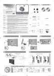
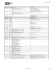
LFD-Monitor Chassis :LH46CKP LH46CKT Model :4 60UT-2 460UTn-2 SERVICE LFD Monitor Manual Contents 1. Precautions 2. Product specifications 3. Disassembly and Reassemble 4. Troubleshooting 5. Wiring Diagram 460UT-2 / 460UTn-2 Contents 1. Precautions............................................................................................................... 1-1 1-1. Safety Precautions.......................................................................................................... 1-1 1-2. Servicing Precautions...................................................................................................... 1-2 1-3. Static Electricity Precautions........................................................................................... 1-2 1-4. Installation Precautions................................................................................................... 1-3 2. Product specifications............................................................................................. 2-1 2-1. Feature & Specifications.................................................................................................. 2-1 2-2. Spec Comparison to the Old Models............................................................................... 2-4 2-3. Accessories..................................................................................................................... 2-5 2-4. Accessories (Sold separately)......................................................................................... 2-6 2-5. Product Differentiation Features...................................................................................... 2-7 3. Disassembly and Reassemble................................................................................ 3-1 3-1. Disassembly ................................................................................................................... 3-1 3-2. Internal Structure............................................................................................................. 3-5 4. Troubleshooting....................................................................................................... 4-1 4-1. Troubleshooting............................................................................................................... 4-1 4-2. No Power......................................................................................................................... 4-2 4-3. No PC / Component / AV (D-SUB) Picture...................................................................... 4-4 4-4. No HDMI Video................................................................................................................ 4-6 4-5. O/S Problems.................................................................................................................. 4-8 4-6. Faults and Corrective Actions........................................................................................ 4-10 4-7. Installing OS (Network).................................................................................................. 4-13 4-8. Adjustment..................................................................................................................... 4-15 5. Wiring Diagram......................................................................................................... 5-1 5-1. Wiring Diagram................................................................................................................ 5-1 5-2. Board Connection............................................................................................................ 5-3 5-3. Board Connection (Main Board)...................................................................................... 5-4 5-4. Board Connection (Network Board)................................................................................. 5-5 5-5. Board Connection (SMPS Board).................................................................................... 5-6 5-6. Functions of Cables and Connectors.............................................................................. 5-7 This Service Manual is a property of Samsung Electronics Co.,Ltd. Any unauthorized use of Manual can be punished under applicable International and/or domestic law. © 2010 Samsung Electronics Co.,Ltd. All rights reserved. Printed in Korea P/N: BN82-01092A-00 3. Disassembly and Reassemble 3. Disassembly and Reassemble This section of the service manual describes the disassembly and reassembly procedures for the monitor. WARNING: This monitor contains electrostatically sensitive devices. Use caution when handling these components. 3-1. Disassembly Cautions: 1. Turn the monitor off before beginning the disassembly process. 2. When disassembling the monitor, do not use any metal tools except for the provided jig. 3. Remove the signal cable and the power cord before beginning the disassembly. Description Picture Description Screws 1. Remocve the 18ea screws and lift up cover Rear. Screw (M4 x L8) S type Screw (M4 x L12) B type 2. Remove the one screw of assy function and separate the cable connected to main PBA. Screw (M4 x L8) S type 3-1 3. Disassembly and Reassemble Description Picture Description Screws 3. Remove the screws (5ea) and angle screws(10ea), separate the main PBA after sererating connector. Screw (M3 x L8) S Type 4. After removing the screws (3ea) and angle screws(2ea), seperate SHIELE JACK. Screw (M3 x L8) S Type 3-2 3. Disassembly and Reassemble Description Picture Description Screws 5. After removing the screws(6ea) and connected cable, seperate MAIN SMPS. Screw (M3 x L8) S Type Screw (M4 x L8) For safety 6. After removing screws(4ea) and connected cable, seperate Network Board. (Only 460UTn-2 Model) Screw (M3 x L8) S Type 7. After removing the screw(6ea) and connected, separate Sub SMPS. (Only 460UTn-2 Model) Screw (M3 x L8) S Type 8. After removing the screws (2ea) and connected cable, seperate Assy Fan. Screw (M3 x L8) S Type 3-3 3. Disassembly and Reassemble Description Picture Description Screws 9. Removing screws(4ea) and separate Holder Wall. Screw (M5 x L12) S type 10.Remove the screws (8ea) and separate Assy P Side. Screw (M4 x L8) S type 11.Remove the screws (8ea) and seperate Bracket PCB/ PANEL. Screw (M4 x L8) S type ※Reassembly procedures are in the reverse order of disassembly procedures. 3-4 3. Disassembly and Reassemble 3-2. Internal Structure Sub Power Board (Only for UTn series) Network Power SMPS Board Network Board Main Board (Only for the UTn series) Processes the video and audio by using the CPU and the video decoder. Receives the PC, AV, Component and HDMI signals and outputs the video data to the panel and the audio data to the speakers or Line-Out. 3-5 3. Disassembly and Reassemble Memo 3-6 1. Precautions 1. Precautions 1-1. Safety Precautions Follow these safety, servicing and ESD precautions to prevent damage and to protect against potential hazards such as electrical shock. 1-1-1. Warnings 1. For continued safety, do not attempt to modify the circuit board. 2. Disconnect the AC power and DC power jack before servicing. 1-1-2. Servicing the LCD Monitor 1. When servicing the LCD Monitor, Disconnect the AC line cord from the AC outlet. 2. It is essential that service technicians have an accurate voltage meter available at all times. Check the calibration of this meter periodically. 1-1-3. Fire and Shock Hazard Before returning the monitor to the user, perform the following safety checks: 1. Inspect each lead dress to make certain that the leads are not pinched or that hardware is not lodged between the chassis and other metal parts in the monitor. 2. Inspect all protective devices such as nonmetallic control knobs, insulating materials, cabinet backs, adjustment and compartment covers or shields, isolation resistorcapacitor networks, mechanical insulators, etc. 3. Leakage Current Hot Check (Figure 1-1): WARNING : Do not use an isolation transformer during this test. (READING SHOULD) NOT BE ABOVE 0.5mA LEAKAGE CURRENT TESTER DEVICE UNDER TEST TEST ALL EXPOSED METAL SURFACES 2-WIRE CORD *ALSO TEST WITH PLUG REVERSED (USING AC ADAPTER PLUG AS REQUIRED) EARTH GROUND Figure 1-1. Leakage Current Test Circuit 4. With the unit completely reassembled, plug the AC line cord directly into a 110/220V AC outlet. With the unit’s AC switch first in the ON position and then OFF, measure the current between a known earth ground (metal water pipe, conduit, etc.) and all exposed metal parts, including: metal cabinets, screwheads and control shafts. The current measured should not exceed 0.5 milliamp. Reverse the power-plug prongs in the AC outlet and repeat the test. 1-1-4. Product Safety Notices Some electrical and mechanical parts have special safetyrelated characteristics which are often not evident from visual inspection. The protection they give may not be obtained by replacing them with components rated for higher voltage, wattage, etc. Parts that have special safety characteristics are identified by on schematics and parts lists. A substitute replacement that does not have the same safety characteristics as the recommended replacement part might create shock, fire and/or other hazards. Product safety is under review continuously and new instructions are issued whenever appropriate. 1-1 1. Precautions 1-2. Servicing Precautions WARNING: An electrolytic capacitor installed with the wrong polarity might explode. Caution: Before servicing units covered by this service manual, read and follow the Safety Precautions section of this manual. Note: If unforeseen circumstances create conflict between the following servicing precautions and any of the safety precautions, always follow the safety precautions. 1-2-1 General Servicing Precautions 1. Always unplug the unit’s AC power cord from the AC power source and disconnect the DC Power Jack before attempting to: (a) remove or reinstall any component or assembly, (b) disconnect PCB plugs or connectors, (c) connect a test component in parallel with an electrolytic capacitor. 2. Some components are raised above the printed circuit board for safety. An insulation tube or tape is sometimes used. The internal wiring is sometimes clamped to prevent contact with thermally hot components. Reinstall all such elements to their original position. 3. After servicing, always check that the screws, components and wiring have been correctly reinstalled. Make sure that the area around the serviced part has not been damaged. 4. Check the insulation between the blades of the AC plug and accessible conductive parts (examples: metal panels, input terminals and earphone jacks). 5. Insulation Checking Procedure: Disconnect the power cord from the AC source and turn the power switch ON. Connect an insulation resistance meter (500 V) to theblades of the AC plug. The insulation resistance between each blade of the AC plug and accessible conductive parts (see above) should be greater than 1 megohm. 6. Always connect a test instrument’s ground lead to the instrument chassis ground before connecting the positive lead; always remove the instrument’s ground lead last. 1-3. Static Electricity Precautions Some semiconductor (solid state) devices can be easily damaged by static electricity. Such components are commonly called Electrostatically Sensitive Devices (ESD). Examples of typical ESD are integrated circuits and some field-effect transistors. The following techniques will reduce the incidence of component damage caused by static electricity. 1. Immediately before handling any semiconductor components or assemblies, drain the electrostatic charge from your body by touching a known earth ground. Alternatively, wear a discharging wrist-strap device. To avoid a shock hazard, be sure to remove the wrist strap before applying power to the monitor. 2. After removing an ESD-equipped assembly, place it on a conductive surface such as aluminum foil to prevent accumulation of an electrostatic charge. 3. Do not use freon-propelled chemicals. These can generate electrical charges sufficient to damage ESDs. 4. Use only a grounded-tip soldering iron to solder or desolder ESDs. 5. Use only an anti-static solder removal device. Some solder removal devices not classified as “anti-static” can generate electrical charges sufficient to damage ESDs. 6. Do not remove a replacement ESD from its protective package until you are ready to install it. Most replacement ESDs are packaged with leads that are electrically shorted together by conductive foam, aluminum foil or other conductive materials. 7. Immediately before removing the protective material from the leads of a replacement ESD, touch the protective material to the chassis or circuit assembly into which the device will be installed. Caution: Be sure no power is applied to the chassis or circuit and observe all other safety precautions. 8. Minimize body motions when handling unpackaged replacement ESDs. Motions such as brushing clothes together, or lifting your foot from a carpeted floor can generate enough static electricity to damage an ESD. 1-2 1. Precautions 1-4. Installation Precautions 1. For safety reasons, more than two people are required for carrying the product. 2. Keeps the power cord away from any heat emitting devices, as a melted covering may cause fire or electric shock. 3. Do not place the product in areas with poor ventilation such as a bookshelf or closet. The increased internal temperature may cause fire. 4. Bend the external antenna cable when connecting it to the product. This is a measure to protect it from being exposed to moisture. Otherwise, it may cause a fire or electric shock. 5. Make sure to turn the power off and unplug the power cord from the outlet before repositioning the product. Also check the antenna cable or the external connectors if they are fully unplugged. Damage to the cord may cause fire or electric shock. 6. Keep the antenna far away from any high-voltage cables and install it firmly. Contact with the highvoltage cable or the antenna falling over may cause fire or electric shock. 7. When installing the product, leave enough space (10cm) between the product and the wall for ventilation purposes. A rise in temperature within the product may cause fire. 1-3 1. Precautions Memo 1-4 2. Product specifications 2. Product specifications 2-1. Feature & Specifications Model 460UT-2 / 460UTn-2 Feature ሪሪ Space(7.3mm) between two neighboring displays ሪሪ Remote control(MDC) using RJ45 / RS-232SC ሪሪ Brightness adjustment using Ambient Sensor ሪሪ IR LOOP-OUT function ሪሪ Digital Loop out(HDMI, DVI, SBB TV, Network)_50 Set ሪሪ DDC-CI (D-sub/DVI), Remote Update ሪሪ Connectivity : D -SUB, DVI, HDMI1/2, DP,AV, RS232C IN/OUT, RJ45, PC Audio(Stereo) In/Out TV/DTV , Network function ሪሪ Programmable PIP (Picture In Picture) : Only Magic info Source ሪሪ Active Size/Position adjustment, Picture mode for Public Display, Gamma adjustment, Schedule for weekends and holidays ሪሪ SW Upgrade by Digital Signal, Addition of Pixel to safety screen ሪሪ FAN/Temperature, Auto Power, Function Key Disable, User Auto Color, DPM Control, Lamp Schedule, OSD Display ሪሪ Service Menu : Always Auto Adjustment, Addition of PC Timing ሪሪ Network - CPU : AthlonX II 2.7GHz (Dual Core) - North Bridge : AMD RS780 - South Bridge : AMD SB700 - Memory : DDR3 SO-DIMM - HDD : SATA 40GB - OS : Windows XP Embedded - Connectors : 3 x USB2.0 port, LAN port, RGB out port, HDMI out port 2-1 2. Product specifications Specifications Item Description Panel AMLCD 46” (LTI460AA04) Optimum Resolution 1366 X 768 Display Size 16:9 Brightness 700cd/m2 Contrast Ratio 3000 : 1 (Typ) Response Time Typical : 6ms / Max : 10ms View angle (H/V) left/right/up/down : 89 °/89 °/89 °/89 ° PC Input RGB, DVI Video input DVI, HDMI, DP, COMPOSITE, Component About TV Resolution TV NTSC 358, PAL/SECAM, PAL60, NTSC4.43, NTSC358, PAL M, PAL N PIP/PBP support PIP support PC/DVI Optimum : 1366 x 768 @ 60 Hz Maimum : 1920 x1080 @ 60Hz Component Optimum : 1366 x 768 @ 60 Hz Maimum : 1920 x1080 @ 60Hz HDMI Optimum : 1366 x 768 @ 60 Hz Maimum : 1920 x1080 @ 60Hz Power consumtion Voltage AC 100 to 240(50Hz/60Hz) Max power consumption 360W (Network Model) 290W (None Network Model) Frequency sync DPMS ≤ 5W Horizontal Frequency 30 ~ 81 kHz Vertical Frequency 56 ~ 85 Hz Clock Frequency 148.5 MHz Sync type Sep/ Comp/SOG Dimensions Set (W x D x H) 1025.7 X 579.8 X 130.0 mm Weight Set :2 6.3 kg (None Network Model) 27.8 kg (Network Model) Package : 3 1.7 kg (None Network Model) 33.2 kg (Network Model) Additional Specification 2-2 HDMI version 1.4a TCO standard None USB support USB 2.0 Supporting color 8bit, 16.7M 2. Product specifications Specifications Item OS Description OS Windows XP Embedded HDD 40 G CPU AMD Athlon II 2.7GHz (Dual Cord ) Memory DDR3 SO-DIMM 2GB Special specification Loop-out function (Network/DVI/HDMI) Remote control using RJ45 / RS-232C Network functon using Magic Info Brightness and IR detection using Ambient Sensor Environmental Considerations Network Model Operating Temperature : 10˚C ~ 40˚C (50˚F ~ 104˚F) Operating Humidity : 10% ~ 80% Operating Temperature : -20˚C ~ 45˚C (-4˚F ~ 113˚F) Operating Humidity : 5% ~ 95% None Network Model Operating Temperature : 0˚C ~ 40˚C (32 ˚F ~ 104˚F) Operating Humidity : 10% ~ 80% Operating Temperature : -20˚C ~ 45˚C (-4˚F ~ 113˚F) Operating Humidity : 5% ~ 95% 2-3 2. Product specifications 2-2. Spec Comparison to the Old Models Chingizkhan (460UTn-2 / 460UT-2 ) Monterosa2 (460UTn / 460UT) Size 46” (1366x768) -> SPVA 46” (1366x768) -> SPVA Spec 700cd/m2, 3000:1, 8ms 700cd/m2, 3000:1, 8ms D-Sub, DVI-D, DP D-Sub, DVI-D Component, AV, HDMI1, HDMI2 Component, AV, HDMI Removable DTV SBB - Output Digital Loopout - Feature RJ45/RS232C MDC Program, OSD Pivot, Remote Control, Video Wall, Digital Loopout External Sensor Kit RS232C MDC Program, OSD Pivot, Remote Control, Video Wall Model Design Panel PC Input Video TV 2-4 2. Product specifications 2-3. Accessories Product Description Code. No Quick Setup Guide BN68-02981A Warranty Card (Not available in all locations) BN68-01789A User’s Manual BN59-01094A Remote Control BP59-00138B Remark Samsung Electronics Service center Power Cord 3903-000455 D-Sub Cable BN39-00244H MagicInfo Software CD, MagicInfo Manual CD (Applicable to the UTn Model only) BN59-00821J BN59-00821K Batteries (AAA × 2) 4301-000121 2-5 2. Product specifications 2-4. Accessories (Sold separately) Product Description Code. No Remark RGB to BNC Cable LAN Cable (Applicable to the UTn Model only) BH39-00211A USB Cable (Applicable to the UTn Model only) RGB-Component Cable RGB - AV Cable Samsung Electronics Service center DVI to HDMI Cable AK68-01439G Wall Mount KIT Wire type : WMN1000BD Frame type : WMN4270SD Network Box (Applicable to the UT Model only) Semi Stand KIT 2-6 BN96-15394A 2. Product specifications 2-5. Product Differentiation Features Remote control through built-in RJ45 and RS-232C ports (up to 100 units.) Case 2 Case 1 1. The basic IP address of the monitor is set to the default in the factory. 2. Connect the monitor and PC with a LAN cable, connect to the monitor, and reconfigure the individual IP address. 3. The MDC program shows the list of IP addresses of the currently connected products and the list of IDs set in the OSD. 4. Using the MDC program, you can control each individual monitor. 2-7 2. Product specifications Illumination Sensor ▷ The illumination sensor consists of a Photodiode and an A/D Lamp Value converter. The photodiode detects the surrounding illumination and the degree of illumination is converted into a digital value through the A/D (Analog to Digital) converter. Depending on this value (Reading Value), the brightness of the lamp on the panel (Lamp Value) is changed automatically. The Lamp Value is set in 10 levels. If the Reading Value exceeds the 100 limit, the lamp brightness remains the maximum 100. 90 ▷ Improves the sensitivity of the existing illumination sensor according to the user conditions. The function has been improved so that the lamp brightness is maintained constant for a specific period of time, or the brightness is changed after a specified delay. In addition, the brightness is changed smoothly and not in steps to resolve the problem when the screen brightness is changed rapidly. … 10 0 Reading Value Digital loop-out function: You can connect up to 50 monitors in a Daisy chain. - DVI/HDMI/DP/Magicinfo Source Supported 2-8 DVI Out DVI Out DVI Out DVI I DVI I DVI I DVI Out DVI I 2. Product specifications Brithness control using Ambient Sensor ▷This Model needs to use remote controller and automatically adjust brightness at the front of product. - Ambient Sensor Control using MDC Application of MagicInfo i Advanced 1. Existing Model ▷ MagicInfo: MagicInfo Pro / MagicInfo i Standard Edition 2. 460UTn-2 : Removing MagicInfo i Standard Version for MagicInfo i Advanced is a charged service. ▷ MagicInfo Pro / MagicInfo i Advanced is installed when the product is shipped. Protection of Image Retention Image retention may not occur when a LCD panel is operated under normal conditions. Normal conditions are defined as continuously changing video patterns. When the LCD panel is operated for a long time with a fixed pattern (over 12 hours), there may be slight difference in voltage between electrodes that work the liquid crystal (LC) in a pixel. The voltage difference between electrodes increases with time, forcing the liquid crystal to lean. When this occurs, the previous image may be seen when the pattern is changed. To prevent this, the accumulated voltage difference must be decreased. ++ ++ ++ ++ + + - - - - -+ - + ++ - ++ + - - - - - - - - - 2-9 2. Product specifications - Type 1. Screen Scroll : Screen is automatically scrolled FLIGHT TIME OZ348 20:30 UA102 21:10 FLIGHT TIME OZ348 20:30 FLIGHT TIME OZ348 20:30 UA102 21:10 Interval : 1 ~ 10 hour (Recommend : 1) Second : 1 ~ 5 second (Recommend : 5) - Type 2. Pixel : One dot on/off and move FLIGHT TIME FLIGHT TIME OZ348 20:30 OZ348 20:30 UA102 21:10 UA102 21:10 Interval : 1 ~ 10 hour (Recommend : 1) Second : 10 ~ 50 second (Recommend : 50) - Type 3. Bar : 2 bars move with crossing each other FLIGHT OZ348 UA102 TIME FLIGHT 20:30 Screen Protection 21:10 OZ348 UA102 FLIGHT TIME 20:30 OZ348 20:30 21:10 Screen Protection 21:10 TIME UA102 Interval : 1 ~ 10 hour (Recommend : 1) Second : 10 ~ 50 second (Recommend : 50) - Type 4. Eraser : 2 blocks move with erasing the display FLIGHT TIME FLIGHT TIME FLIGHT TIME OZ348 20:30 OZ348 20:30 OZ348 20:30 UA102 21:10 UA102 21:10 UA102 21:10 Interval : 1 ~ 10 hour (Recommend : 1) Second : 10 ~ 50 second (Recommend : 50) 2-10 2. Product specifications HDCP Operation ♦ HDCP: A decoding function designed to protect digital content included in HDMI signals. ♦ The operating diagram below shows how the picture is displayed when a device that has the HDCP feature is connected to a monitor that contains an HDCP authentication code. The picture is displayed after an authentication (decoding) process via the HDMI’s I2C line. 1. Authentication takes about 2 seconds. 2. If authentication fails: A static screen will be displayed. →C heck the supported resolution. Turn the power switch off and on (for re-authentication). Enter the HDCP key again. Check that the device supports HDCP authentication. 2-11 2. Product specifications Memo 2-12 4. Troubleshooting 4. Troubleshooting 4-1. Troubleshooting 1. Before troubleshooting, setup the PC ‘s display as below. • Resolution: 1366 X 768 • H-frequency: 66 kHz • V-frequency: 60Hz 2. If no picture appears, make sure the power cord is correctly connected. 3. Check the following circuits. • No raster appears: Function PCB, Main PCB, I/P PBA • 55V develop but no screen: Main PBA • 5V does not develop: I/P PBA 4. After soft power turn off, push the mute → 1 → 8 → 2 → power on and so enter the Service Menu. If you choose the reset, the monitor automatically returns to factory reset. 4-1 4. Troubleshooting 4-2. No Power Symptom -- When turning on the Power button after connecting the power, the LED at the front of the monitor does not operate. -- Check the SMPS board power fuse and the SMPS board output power. Major checkpoints -- Check the connections for the SMPS board and the Main board inside the monitor. -- Check the Main board power part and check also whether there is any abnormal output at other output terminals. CN101 R901 BD112 BD132 IC101 (Scaler) IC107 Does 5.3V appear at 4pin of CN101? No Check the SMPS Board. Yes Diagnostics Does 12V appear at R901? No If you cannot see picture Check the PANEL Yes 1 Does 1.25V appear at 2pin of IC107? No Check IC107. Yes 2 Does 3.3V appear at BD132? No Check Scaler IC101. Yes 3 Does 12V appear at BD112? No Chcek around CN101. Yes The Scaler is abnormal. Replace the main board. Caution 4-2 Make sure to disconnect the power before working on the SMPS board. 4. Troubleshooting 4-2-1. Waveform 1 2 3 4-3 4. Troubleshooting 4-3. No PC / Component / AV (D-SUB) Picture Symptom Major checkpoints -- Though the LED power turns on, the screen is blank when connecting the VGA cable. -- Check the D-sub cable connections. -- Check whether the LVDS cable is connected correctly to the panel. -- Check whether the lamp connector of the panel is connected correctly to the SMPS board. CN901 IC101 (Scaler) CN201 Does the LED light up when turn on the power? Diagnostics No Check the power port. Yes Does 5V appear at of 9pin of CN201? No Check the cable connection. Yes Does waveform as the figures at 13 pin of CN201(H-sync) 5 and 14 pin (V-sync) 6Appear? No Check around CN201. Yes Does clk signal appear at 16&17 pin of CN901? Yes No Scaler (IC101) problem! Replace main board Check the cable between the main board and panel and replace the LCD panel. Caution 4-4 Make sure to disconnect the power before working on the SMPS board. 4. Troubleshooting 4-3-1. Waveform 5 6 4-5 4. Troubleshooting 4-4. No HDMI Video Symptom Major checkpoints -- The LED power turns on but the screen is blank when the HDMI cable is connected. -- Check the HDMI cable connections. -- Check whether the LVDS cable is connected correctly to the panel. -- Check whether the lamp connector of the panel is connected correctly to the SMPS board. CN901 IC101 (Scaler) CN301/CN302 Does the LED light up when turn on the power? Diagnostics No Check the power port. Yes Does 5V appear at Pin 18 of CN301/302 (HDMI port) ? No Check the cable connection. Yes Does the waveform as the figure at R335/R331(HDMI_SCL) 7 and R336/ R332(HDMI_SDA) 8 appear? No Replace IC303(TMDS Switch) Yes Does clk signal appear 16/17 pin of CN901? No Scaller (IC101) Problem Replace mainboard Yes Check the cable between the main board and panel and replace the LCD panel. Caution 4-6 Make sure to disconnect the power before working on the SMPS board. 4. Troubleshooting 4-4-1. Waveform 7 8 4-7 4. Troubleshooting 4-5. O/S Problems Symptom Major checkpoints -- The monitor does not boot. -- Check the BNC cable connections. -- Check whether the LVDS cable is connected correctly to the panel. -- Check whether the lamp connector of the panel is connected correctly to the SMPS board. A B Diagnostics When turning on power in Magic Info mode, Does the Sam Sung Logo appear on display? No Check the LED. A Yes Does appear Blue Screen as like 9? No Restore OS Image or Replace HDD. B No Restore OS Image or Replace HDD. B Yes During the Booting ,Does appear error message as like 0. Yes Check the CPU and DIMM Memory status , And Replace the Network B/D. Caution 4-8 Make sure to disconnect the power before working on the SMPS board. 4. Troubleshooting 4-5-1. Screens to Check 9 0 4-9 4. Troubleshooting 4-6. Faults and Corrective Actions Category Defect symptoms and Actions taken Model: 400PXn Beethoven 2 CPU Socket problem - Symptoms: V arious defects found in marketed products - Windows boot-up failure, Windows freeze-up, Windows restart, Blue screen, Windows error message, etc. Defect correction history - Causes: Poor contact occurred between the CPU and the CPU socket due to the CPU socket’s structural problem and strain. 1) Structural problem in the CPU socket 2) Strain due to the gap pad’s thickness between the CPU heat sink and the instrument’s shield cover. - Actions taken: 1) Requested Foxconn, CPU socket manufacturer, to change the shape of the socket’s contact area: to lengthen the pin’s contact or to reshape the contact area into a hook shape. 2) The PBA line performed shock tests during a performance test on the network board to sort out defective sockets 3) Changed the gap pad’s thickness (from 3.2mm to 2.0mm) Model: 400PXn Beethoven 2 Problems: Defects in Samhwa’s 16V 100uF Caps and field defects in Japan for the Beethoven 2 model Symptoms: S ound noise when opening Caps (Japan, Dec. ‘07)/ BNC screen noise when opening TSED PBA Caps (Jan. ‘08) Actions taken: Took temporary measures Defect correction history - Samhwa in Tianjin discontinued manufacturing 100uF/16V, which was supplied by Samhwa in Korea instead. (Jan. 30) - after an alternative was set up, manufacturing was carried out to successfully cover the production volume, which was originally to be supplied by Tianjin, in December before Jan. 30 - Performed a comparative analysis of 100uF/16V M-Type (105 degree, 3000 hour) between Korea and Tianjin Samhwa - Performed a comparative analysis of Tianjin’s production volume between July ~ Aug. and Dec. (Jan. 29) - Established a dualization schedule - development evaluation (Jan. 25) - Set up alternative measures and notified results (parts warranty) (notified later) 4-10 Remarks 4. Troubleshooting Category Defect symptoms and Actions taken Remarks Model: 400PXn/ DXn Beethoven 2/ Beethoven Plus - EWF related -E WF (Enhanced Writer Filter)? Protects booting volume in unnecessary writing; improves system robustness; protects booting volume from possible power failure; protects flash volume from all writings; and increases the life span of flash devices. Preset to Enable by default. Defect correction history -E WF Enable: During system restart after writing data (program installation, contents copy, etc) on the FDM (Flash Disk Module) of the network board, the previously written data will be deleted. Upon leaving the factory, the FDM is divided into C and D drives, in which EWF is set to, respectively, Enable and Disable. -E WF Disable: During system restart after writing data on the FDM, the previous data will remain maintaining the general PC use environment. Powering on or off while EWF is on Disable may cause the corruption of Windows installed on the FDM. -S ince there have been many cases that resulted in problems (Windows boot-up failure, blue screen, etc.) while using with EWF Disable, you are recommended to maintain the EWF Enable mode. Model: 400PXN -S ymptoms: Repeated power ON/OFF Set Open check: Defects in network power (Capxon electrolysis Cap. swelling up) and in the network board (normal screen when detached) Defect correction history -C auses: As the network power does not work from the Capxon electrolysis Cap. swelling up, the system keeps restarting (Cap. life span problem) -A ctions taken: Stopped using the Capxon electrolysis Cap. B/S has been complete now. ♣ Check point: Network power has been changed to one that satisfies 40,00 hour MTBF (BN96-03319A -> BN96-03319B) 4-11 4. Troubleshooting Category Defect symptoms and Actions taken Model: 400PXn Beethoven 2 - Power sequence problem -S ymptoms: During hard power Off -> On with soft power set to Off, a defect that the MagicNet source displays only a black screen occurred. -C auses: The MagicNet source displays only a black screen during hard power Off -> On with soft power set to Off. -> This symptom may have two different causes. * Normal condition: The network board, which started up with network power during hard power Off -> On with soft power Off, is shut down by NW_BT. If soft power is turned on again, the network board normally starts up. Defect correction history 1) Abnormal condition: If AC power is applied under low AC power and full discharge conditions, NW_BT is ignored and the network board proceeds with booting. If soft power is turned on again, the network board shuts down (black out). 2) Abnormal condition: During hard power Off -> On with soft power Off, booting with network power fails. = > On the contrary, booting by NW_BT is achieved. If soft power is turned on again, the network board shuts down (black out). Booting with network power is achieved when the ring signal terminal on South Bridge is on High, and if the pin under the terminal is opened, some network boards recognize it as on Low and cause failure. - Actions taken: Corrected the network board’s BIOS and Main MICOM Code (the same action taken for both of the above causes) Model: 323T (CK32) - Problems: In the French market, performed follow-up actions on complaints about 323T (CK32) display. The native resolution (1024*768 & 1280*768) of SM323T (CK32) was claimed to be foggy when compared to LG products (Two samples, Jan. 2004). Defect correction history - Causes: The main scaler’s sharpness was set to Mini. Addition of an anti-ESD zener diode to the input terminal deteriorated picture quality. - Actions taken: Changed the main scaler’s sharpness from 0x00h to 0x18h. Removed the zener diode from the input terminal to replace it with a two-way diode. Modified PCB REV from 458B to 458C. ♣ CHECK POINT : 1> Test pattern: Ran an Internet screen (readability) or test program. - Check list: Blurred/ foggy screen, sharpness, etc. 2> Checked if PCB REV for the concerned model was modified (e.g., Chagall 32 inch PCB REV: 458C). 4-12 Remarks 4. Troubleshooting 4-7. Installing OS (Network) 1. Making a DOS booting USB 1) Install and run 1123729948_SP27213.exe. 2) Choose a driver equipped with USB memory and select FAT as the file system. 3) Decompress EBD.zip which is attached. And select it for location of Format Option-Create a DOS startup disk 2. SFIM Download 1) Copy the SFIM.exe file from the SFIM Ver. 2.0 folder and paste it to the USB memory root directory. 2) Remove the USB memory from the PC. 3. When the USB memory is ready, connect the USB keyboard and USB memory to their corresponding USB ports on the network board of the product and then turn the power on. 4. BIOS setup: After turning the power on, press F2 on the screen below to start the BIOS screen. ➩ 5. Move to <Info>→<Boot> tab using <→> on the keyboard. Select the connected USB using <↓> on the keyboard. Change the boot priority order to 1 using the <+>button. 6. Press F10 to select Yes from Setup Confirmation and press Enter. 7. Running SFIM After BIOS setup, it operates Command Prompt . Type the command as below. C:\> sfim /r:1 image.sfi In image.sfi, the image can be changed randomly (e.g., 320MX.sft, etc.). 4-13 4. Troubleshooting 1. If the blue progress bar reaches its fullest extent (100%), it means that the process is complete. Turn the LCD monitor off. 2. Remove the USB memory from the main body of the LCD monitor. 4-14 4. Troubleshooting 4-8. Adjustment 4-8-1. Entering Service Mode with Remote Control 1. Entering Service Mode - Power Off - INFO MUTE 1 8 2 Power On FACTORY (Using factory Remocon) 4-8-2. Service Mode Menu Service Menu Auto Color White Balance Main Advanced Sharpness Enhancers Back End Audio AV Video System Option Spread Spectrum Panel Info Reset Checksum L-CK46MWWAC-0900.0 10.04.09 Menu Auto Color White Balance Main Advanced Sharpness Enhancers Description Auto-Color Adjusting Adjust color by R/G/B Offset, Gain Improving Sharpness Enhance Image quality Back End Audio AV Video System Option Spread Spectrum Panel Info Reset Checksum Setting the Audio delay Y and C Sync Control Adjust Baudrate, nMFM/Function Key Operation, and so on. Spread Spectrum Panel using time, replacing times Factory Reset Micom Code version and Date 4-15 4. Troubleshooting AutoColor Part PC analog Only ( 1024x768@60 16gray pattern) Color control operates normally only in certain modes of certain patterns, but in other cases, the operation may distort color. Also, color control is not normal when controlling color in a mode other than XGA 60Hz. Service Menu Auto Color White Balance Main Advanced Sharpness Enhancers Back End Audio AV Video System Option Spread Spectrum Panel Info Reset Checksum Extreme caution needed.!! AV (NTSC or PAL, Color bar pattern) Component ( 720P, Color bar pattern) Color control operates normally only in certain modes of certain patterns, but in other cases, the operation may distort color. L-CK46MWWAC-0900.0 10.04.09 Extreme caution needed.!! White Balance Part Used for color control. Service Menu S ERVICE Service MENUMenu Auto Color Auto WhiteColor Balance White Balance Sharpness Main Advanced Main Advanced Sharpness Enhancers Enhancers Back End ISR FPGA Audio Audio AV Video System Option AV Video System Spread Spectrum Option Panel Info Spread Spectrum ResetInfo Panel Checksum Reset Check Sum L-CK46MWWAC-0900.0 10.04.09 L-LB46MWWAC-0805.0 10.02.25 -0904.0 But excessive setting may saturate the color. Extreme caution needed.!! White Balance On ON Sub Bright 0 OFF Sub Contrast 100 RED Offset 100 GREEN Offset 100 BLUE Offset 100 RED Gain 100 GREEN Gain 100 BLUE Gain 100 Register value in the Scaler RED / BLUE / GREEN Adjust the Gain and Offset 4-16 On : D isplay factory adjusting value Off : D isplay default setting value 4. Troubleshooting Sharpness Part SERVICE Service MENUMenu Service Menu Auto Color White Balance Auto Color Advanced Sharpness WhiteMain Balance Enhancers Sharpness Main Advanced ISR FPGA Enhancers Audio Back End AV Video System AudioOption AV Video System Spread Spectrum Panel Info Option Reset Spread Spectrum Panel Check Info Sum ResetL-LB46MWWAC-0805.0 10.02.25 Checksum -0904.0 L-CK46MWWAC-0900.0 10.04.09 Adjusting the sharpness of displayed image. Main V Peaking Y 32 Main V Peaking UV 16 Main V Peaking Coring 16 Main V Peaking Region 1 Threshold 48 Main V Peaking Region 1 Gain 4 Main V Peaking Region 2 Threshold 170 Main V Peaking Region 2 Gain 4 Main H Peaking Y 32 Main H Peaking UV 16 Main H Peaking Coring 8 Main H Peaking Region 1 Threshold 48 Main H Peaking Region 1 Gain 4 Main H Peaking Region 2 Threshold 170 Main H Peaking Region 2 Gain 4 Adaptive Sharpness Noise Coring Low High Medium Off Main V Peaking Y Main V Peaking UV Main V Peaking Coring Main V Peaking Region 1 Threshold Main V Peaking Region 1 Gain Main V Peaking Region 2 Threshold Main V Peaking Region 2 Gain Main H Peaking Y Main H Peaking UV Main H Peaking Coring Main H Peaking Region 1 Threshold Main H Peaking Region 1 Gain Main H Peaking Region 2 Threshold Main H Peaking Region 2 Gain Sharpness Noise Coring Scaling Filter Sharpness Control - Peaking Y / Peaking UV Adjusts the sharpness of brightness (Y) and color tone (UV). When in the range of 1-127 the higher the number the sharper the image, and when in the range of 128-255 the higher the number the softer the image. If the sharpness is at too high of a level then it may cause side effects such as more apparent image noise, etc. Noise Coring Control - Peaking Coring Represents only large edges of images vividly, instead of amplifying small edges assuming that they are noise. Noise Coring Out Peaking Coring Determines a threshold value to highlight sharpness. Sharpness Filter Out NonLinear Sharpness Control - Peaking Resion1/2 Threshold, Gain Instead of applying sharpness evenly to the entire image, divides frequencies into sections applying different gains for each section. Nonlinear Out Peaking Region1 Gain Peaking Region2 Gain Peaking Region2 Threshold Peaking Region1 Threshold Noise Coring Out 4-17 4. Troubleshooting Enhancers Part SERVICE Service MENU Menu Service Menu Auto Color Auto Color White Balance White Balance Main Advanced Sharpness Main Advanced Sharpness Enhancers Enhancers Back End ISR FPGA Audio Audio AV Video System AV Video System Option Option Spread Spectrum Spread Spectrum Panel Info Panel Info Reset Reset Checksum Check Sum L-CK46MWWAC-0900.0 10.04.09 L-LB46MWWAC-0805.0 10.02.25 -0904.0 Adjust to display the clear and sharp image. This function is used to adjust the appropriate value for each target region. Change only when it is needed. HLE Threshold 10 HLE Gain 180 HDP Threshold 21 HDP Gain 71 HCE Threshold 15 HCE Gain 25 VDP Threshold 27 VDP Gain 3 HLE : Horizontal Large Edge Enhancer HDP : Horizontal Detail Processor HCE : Horizontal Chroma Enhancer Audio Part Service Menu Auto Color White Balance Main Advanced Sharpness Enhancers Back End Audio AV Video System Option Spread Spectrum Panel Info Reset Checksum L-CK46MWWAC-0900.0 10.04.09 Audio delay Setting (Set for the video and audio synchronization.) AUDIO DELAY 0 DVI Audio Delay 0 AV Audio Delay 0 Component Audio Delay 0 HDMI1 Audio Delay 0 HDMI2 Audio Delay 0 DisplayPort Audio Delay 0 Magicinfo Audio Delay 0 TV (Internal] Audio Delay 0 TV (External) Audio Delay 0 EXT Volume Scale 4-18 ON PC Audio Delay 100 Speaker EQ On EXT Prescale Speaker 100 4. Troubleshooting AV Video System Part SERVICE Service MENUMenu Menu Service Auto Color Auto Color White Balance White Balance Main Advanced Sharpness Main Advanced Sharpness Enhancers Enhancers Back ISREnd FPGA Audio Audio AVAV Video System Video System Option Option Spread Spectrum Spread Spectrum Panel Info Panel Info Reset Reset Checksum Check Sum L-CK46MWWAC-0900.0 10.04.09 L-LB46MWWAC-0805.0 10.02.25 -0904.0 AV size, position Adjustment H,V size / H,V Position Video System NTSC H Size 0 V Size 0 H Position 0 V Position 0 Y/C Dealy 50 4-19 4. Troubleshooting Option Part Service Menu Auto Color White Balance Main Advanced Sharpness Enhancers Back End Audio AV Video System Option Spread Spectrum Panel Info Reset Checksum L-CK46MWWAC-0900.0 10.04.09 Option Control -. Baudrate Speed Setting (The default value is 9600.) Baudrate Check nMFM Enabled DVI Hot-Plug Delay 9 Watch Dog Disabled HDMI1 Hot-Plug Delay 9 PDP Download HDMI2 Hot-Plug Delay 9 BNC SOG Detect HDMI EQ HDMI EQ Value 9600 Auto 0 HDMI1 Pin Set Auto HDMI2 Pin Set Auto Always Auto Adjustment Off PC Timing Add 4-20 Network On in DPMS Disabled Network Off Option Disabled Off Enabled 4. Troubleshooting Spread Spectrum/Panel Info Part Service Menu Auto Color White Balance Main Advanced Sharpness Enhancers Back End Audio AV Video System Option Spread Spectrum Panel Info Reset Checksum L-CK46MWWAC-0900.0 10.04.09 Spread Spectrum Adjustment The application status of Spread spectrum Amplitude and Period Setting Spread sp 1 0 : Disable 1: Enable Amplitude 1 Period 10 Information of Panel Panel Time Panel Ch. No. 0 Hr 0 Panel Time: the total operating hours of the panel is 0 Hr (default). Panel Ch. No.: the panel has been replaced 0 times (default; increases by one every time the panel is replaced) Reset/Checksum Part Service Menu Auto Color White Balance Main Advanced Sharpness Enhancers Back End Audio AV Video System Option Spread Spectrum Panel Info Reset Checksum L-CK46MWWAC-0900.0 10.04.09 Reset : Factory Reset Reset the setting on the Service Menu to the default setting. Need to turn the Power On/Off after reset Checksum The 4 digit serial number regarding the micom code is displayed if you select this. 4-21 4. Troubleshooting 4-8-3. Entering DDC Connect the parallel port (printer port) of the PC and the D-SUB/DVI/HDMI cable of the monitor by using the DDC manager jig. For the connection, refer to the following figure. DVI to HDMI Cable (HDMI DDC) HDMI DDC (HDMI1/HDMI2) PC DDC PC Conncet parallel of PC DVI DDC < Input DP DDC to Main Board as code> 4-22 4. Troubleshooting Input Procedures 1. Select Open File 2. Select Port 1 (D-SUB) / Select Port 2 (DVI) / Select Port 3 (HDMI) 3. Select the DDC file. 4. Click the Next (OK) button. 1 2 3 4 5. Enter the serial number of the monitor. When Digital is input after Analog is input, repeat Steps 2~5. 5 4-23 4. Troubleshooting Must Do’s after replacing the board 1. Main Board ሪሪ Check the adjusted PC color status ሪሪ DDC Input (Input both Analog and Digital) - This is for registering information about the supported resolution. - The product serial number and EDID should also be entered. ሪሪ Reset after entering the Service mode and turn off the main power. 2. Network Board ሪሪ Press Info and check the version of Network. ሪሪ Check the versions of HDD and BIOS and see if they are the same as the version of the server program. ሪሪ If the version is different, refer to the descriptions above and upgrade the program. ሪሪ Upgrade the program and turn the power off/on. ሪሪ Check if there are IC-DRAM and Battery. 4-24 6. Wiring Diagram 6. Wiring Diagram 6-1. Wiring Diagram 6-1 6. Wiring Diagram 6-2 6. Wiring Diagram 6-2. Board Connection Sub Power Board SMPS Board Main Board Network Board (Only for the UTn series) 6-3 6. Wiring Diagram 6-3. Board Connection (Main Board) 1 2 4 3 5 18 6 17 7 16 8 15 9 10 14 1 Function to Main connector 10 DC-DC 2 SMPS to MAIN connector 11 RS232C OUT 3 FFC connector (31P) 12 RS232C IN 4 IR Loop out IN/OUT 13 LAN 5 D-SUB IN 14 HDMI2(connected to network) 6 AUDIO IN 15 HDMI1 7 AV AUDIO IN 16 DP 8 COMPOSITE 17 DVI IN 9 AUDIO OUT 18 DVI OUT (Digital Loop out) 6-4 11 13 12 6. Wiring Diagram 6-4. Board Connection (Network Board) 1 2 3 4 5 1 16Pin power Connector : Network to Sub SMPS 2 RGB OUT 3 HDMI out (magicinfo) 3 LAN Connector 3 USB Connector 4 Bios Clear Button : PC bios Reset 6 6-5 6. Wiring Diagram 6-5. Board Connection (SMPS Board) 1 2 3 2 4 1 30Pin connector : SMPS to MAIN PBA 2 2 Pin Connector : Sub SMPS to Network PBA 3 30pin to 14/14 Pin Connector : PANEL Inverter 4 16 Pin Harness : Sub SMPS to Network PBA 6-6 6. Wiring Diagram 6-6. Functions of Cables and Connectors Use LVDS Cable FAN Cable Code BN96-12453E BN39-00950A Role Sends LVDS signals from the video board to the panel. Sends fan power and signals from the fan to the video board. Use Inverter Cable Lead Connector (Only Network Model) Code BN39-01193C BN39-00984L Role Supplies power from the SMPS to the panel inverter. Supplies power from the sub-SMPS to the network board. Use Lead Connector AC Cable (Only Network Model) Code BN39-01065A BN39-00618R Role Sends signals from the main SMPS to the video board. Supplies power from the main SMPS to the subSMPS. Photo Photo Photo 6-7 6. Wiring Diagram Use LVDS Cable FAN Cable Code BN96-14677A BN39-01352A Role Function key (connected to the main video board) A lead connector contained in the function ass’y. Use CBF SIGNAL-HDMI Photo Photo 6-8 Code BN39-01359A Role A cable that connects signals between the Magic Info network and main board