Download DCS Computer Hardware Digital to Digital Converter User's Manual

Transcript
dCS 974
Digital to Digital Converter
User Manual
Software version 1.0x
May 2001
© 2001 dCS Ltd
All rights reserved. Reproduction of this manual in any manner whatsoever,
without the written permission of dCS1 is strictly forbidden. Additional copies of
this manual may be obtained from dCS.
Information contained in this manual is subject to change without notice, and
whilst it is checked for accuracy, no liabilities can be accepted for errors.
1
dCS Ltd is Data Conversion Systems Ltd. Company registered in the England no. 2072115
dCS 974 User Manual
dCS Ltd
Manual part no: DOC1241121A1
Contact dCS on + 44 1799 531 999
(inside the UK replace + 44 with 0)
Manual for Software Version 1.0x
May 2001
Page 2
Document No: OS-MA-A0124-112.1A1
email to: [email protected]
web site: www.dcsltd.co.uk
dCS 974 User Manual
dCS Ltd
Manual for Software Version 1.0x
May 2001
PRODUCT OVERVIEW
The dCS 974 DDC (Digital to Digital Converter) is a high performance real time
sample rate and format converter, developed from our highly successful
dCS 972. It is designed for studio applications where source material is available
in one format, but outputs are required in other digital formats in real time. For
example, archives might be made for storage in 24/192 or 24/176.4 formats,
and then used to produce output in SACD, DVD, CD and other multimedia
formats. AES3, SPDIF, SDIF-2 and DSD formats are all supported, and multiple
units may be synchronised for stable multi-channel operation.
The unit is mains powered and is housed in a 2U (3.5”) high 19” rack mounting
case. It may be controlled either from its front panel, or from a software based
remote control running on a PC. Frequently used Setups may be stored and recalled later. The last setting is automatically stored on power down, so that fixed
installations may be set up at leisure, installed and then left alone. Unauthorised
alterations to settings may be prevented by a “panel lock out” feature.
Numerous monitoring functions are provided – both for the audio signal and for
messaging attached to it. The unit has bit activity and level meters, and
message manipulation. CRC, parity and invalid errors may be monitored and
reported, so that “right first time” transfer to disc plants may easily be achieved.
The unit is highly software based, and more functions and features are added
2
from time to time. Software updates from dCS are free!
Formats
•
•
•
•
DSD at 2.822MS/s (see page 71)
PCM from 192 kS/s down to 11.025 kS/s (see page 43)
PCM data formats supported are: AES/EBU (XLR), Dual (2 wire) AES3
(XLR), Quad (4 wire) AES3 (XLR), SPDIF (Phono, Toslink and BNC) and
SDIF-2 (see page 70)
DSD data formats supported are SDIF-2 (BNC), SDIF-3 (BNC) and DSD
Quad (4 wire - XLR)
Functions
•
•
•
•
•
•
•
•
•
•
•
Sample Rate and Format Conversion (page 34)
Multi-channel Sync capability (page 42)
Bit for bit multiplex/de-multiplex mode (page 39)
PCM to DSD, DSD to PCM
DC Removal for DSD
Multiple filters on many major sample rate conversions (page 45)
Dither – 3 types (see page 47)
Noise shaping – 10 different options on all major PCM sample rates (page
47).
Output Level control with “Maximise” (page 48)
Balance control (page 48).
Digital Silence out with digital silence in (page 50)
Syncing
Comprehensive - can sync to Wordclock or AES reference, or signal, and sync
to video option available.
2
free if we email them, and you download from a PC COM port. Low cost if you ask us for EPROMs or other
media - we charge for media and handling.
Manual part no: DOC1241121A1
Contact dCS on + 44 1799 531 999
(inside the UK replace + 44 with 0)
Page 3
Document No: OS-MA-A0124-112.1A1
email to: [email protected]
web site: www.dcsltd.co.uk
dCS 974 User Manual
dCS Ltd
Manual for Software Version 1.0x
May 2001
Monitoring
Bit Activity (page 56), Stereo Output Level (page 57), and CRC, Parity & Invalid
flag errors in the input data (page 52).
Test Generator
High quality (160 dB) signal generator with mHz resolution (page 53). Can be
dithered and/or noise shaped truncated.
Ease of Use
User programmable set-ups (page 61)
Pre-loaded setups
Remembers last settings
Lockouts (page 64)
Manual part no: DOC1241121A1
Contact dCS on + 44 1799 531 999
(inside the UK replace + 44 with 0)
Page 4
Document No: OS-MA-A0124-112.1A1
email to: [email protected]
web site: www.dcsltd.co.uk
dCS 974 User Manual
dCS Ltd
Manual for Software Version 1.0x
May 2001
About this Manual
If you have not used a dCS 974 before, please read the section Using Your
dCS 974 For The First Time on page 110.
This manual has been arranged with the most commonly used sections placed
first:
•
•
•
•
•
•
•
table of contents (page 6)
step-by-step (page 10) and applications guides (page 22)
detailed software and hardware information (page 34)
technical information (page 70)
information for first time users (page 110)
options, maintenance and troubleshooting (page 114)
index section (page 124)
References to other sections in the text have the Section Name, page … with
Section Name in bold. Sometimes, if you are reading a soft copy of the manual,
section names and page numbers are hyperlinks – click on them, and you will
go there.
IMPORTANT!
Important information is presented like this - ignoring this may cause you to
damage the unit, or invalidate the warranty.
The manual is designed to be helpful. If there are points you feel we could cover
better, or that we have missed out - please tell us.
About Sample Rates
All references to sample rates in this manual use the unit kS/s (kilo Samples per
second) rather than the technically incorrect kHz.
Manual part no: DOC1241121A1
Contact dCS on + 44 1799 531 999
(inside the UK replace + 44 with 0)
Page 5
Document No: OS-MA-A0124-112.1A1
email to: [email protected]
web site: www.dcsltd.co.uk
dCS 974 User Manual
dCS Ltd
Manual for Software Version 1.0x
May 2001
CONTENTS
Product Overview ...............................................................................................3
About this Manual
About Sample Rates
5
5
Contents ..............................................................................................................6
Step-by-Step Guide ..........................................................................................10
Preliminaries
Step 1 – Selecting an Input
Connecting to a Single AES or SPDIF source
Connecting to a PCM SDIF-2 source
Connecting to a Dual AES Source
Connecting to a Quad AES source
Connecting to a DSD SDIF-2 source
Connecting to a DSD Quad source
Step 2 – Setting the Sync Source
Syncing to an External Wordclock
Syncing to an AES/EBU Reference
Step 3 - Setting a Conversion
Format Conversion
Sample Rate Conversion
Step 4 – Connecting the Outputs
Connecting a Single AES or SPDIF Output
Connecting the SDIF-2 Output
Connecting the Dual AES Outputs
Connecting the Quad AES or DSD Quad Outputs
Connecting the DSD SDIF-2 or DSD SDIF-3 Output
Step 5 – Reducing the Output Wordlength
Other Settings
10
11
11
11
12
12
12
12
13
13
14
15
15
16
18
18
18
18
18
18
19
21
Typical Applications.........................................................................................22
Converting a 24/96 recording to CD format
Demultiplexing a 24/96 Dual AES recording (Bit for Bit)
Upsampling a CD
General Sample Rate Conversion and Distribution
PCM to DSD
Using a Master Clock
Converting Quad AES to CD Format
Multi-channel Sample Rate Conversion – bit aligned sources
Multi-channel Sample Rate Conversion – Using a Master Clock
Multi-channel Sample Rate Conversion – with more alignment tolerance
Multi-channel Sample Rate Conversion – with multiple sample rates out
22
23
24
25
26
27
28
29
30
31
32
The Software – Menu and Setups ...................................................................34
Navigating through the Menu – what the On-Screen symbols mean
Top Menu
Sample Rate Conversion
Format Conversion
Error Monitoring
Test
Info
Bit Activity Monitors
Level Meters
Display
Sample Rate Conversion / Format Conversion Submenu
Audio Input Select
Sync Source
Multiple Channel Sync
Input Sample Rate
Output Sample Rate
Output Mode
Filter
Output Word Length
Manual part no: DOC1241121A1
Contact dCS on + 44 1799 531 999
(inside the UK replace + 44 with 0)
Page 6
36
38
38
39
39
39
39
40
40
40
41
41
41
42
43
43
45
45
46
Document No: OS-MA-A0124-112.1A1
email to: [email protected]
web site: www.dcsltd.co.uk
dCS 974 User Manual
dCS Ltd
Manual for Software Version 1.0x
May 2001
Noise Shaping
Dither
AES Message Edit
SPDIF Message Edit
Gain/Balance and Maximise
Swap Channels
Phase
Detect Silence
De/Pre-Emphasis
Display Customise
Error Monitor Submenu
Error Hold and Reset
Test Submenu
Generator Overview
Controlling the Generator
Generator Amplitude Adjustment
Generator Frequency Adjustment
Self Test
Info Submenu
Bit Activity Monitor Submenu
Bit Activity Monitoring Overview
Setting the Monitor
Level Meters Submenu
Level Meter Overview
Turning the Level Meters On
Meter Type (Bar or Numerical)
Decay Time
Peak Hold
Using the dCS 974 to monitor a track
Watch Out for this One!
Display Submenu
Setups and Locking the Front Panel
Storing a Setup
Fixed Setups
Recalling a Setup
Locking Out Changes, and Unlocking Again
47
47
48
48
48
49
49
50
50
50
52
52
53
53
53
54
54
55
56
56
56
56
57
57
57
58
58
58
59
59
60
61
61
63
63
64
The Hardware – Controls and Connectors ....................................................66
Rear Panel
Signal Inputs
Signal Outputs
Control and Power
Additional Information
Front Panel
Power Indicator
OPERATION buttons
MEMORY buttons
LCD display
LED indicators
Rotary encoder
66
66
67
67
67
68
68
68
68
68
69
69
dCS 974 Technical Information.........................................................................70
Digital Data Formats Supported
DSD
PCM Input and/or Output Performance
Clocking
Sample Alignment
Multiple Channel Sync’ing
Multiple Channel Multiple Sample Rate Synchronising
Noise Shaping
Dither
Digital Interface Specifications
Message Handling
AES/EBU Message Handling
SPDIF Message Handling
Manual part no: DOC1241121A1
Contact dCS on + 44 1799 531 999
(inside the UK replace + 44 with 0)
Page 7
70
71
73
76
77
81
83
84
85
86
88
88
89
Document No: OS-MA-A0124-112.1A1
email to: [email protected]
web site: www.dcsltd.co.uk
dCS 974 User Manual
dCS Ltd
Manual for Software Version 1.0x
May 2001
SDIF-2 Message Handling
SDIF-3 Message Handling
Power Consumption
Size, Weight and Operating Conditions
90
90
91
92
dCS 974 Performance Curves...........................................................................94
General Technical Information......................................................................104
Word Length Reduction
104
Using Your dCS 974 For The First Time ........................................................110
What’s in the Box?
Supply Voltage Setting
Getting Started
Installing the Unit in a Rack
110
110
110
112
Options ............................................................................................................114
Locking to Video Sample Rates
Mains Supply Voltage
Ordering Options for a New Unit
Having Your Options Changed
114
114
114
114
Maintenance and Support..............................................................................116
Hardware
Service & Maintenance
User Changeable Parts
Software
Installing New Software
Warranty
Initial Warranty
Extended Warranty
Warranty Exclusions
Obtaining Service
Update or Calibration
Safety and Electrical Safety
116
116
116
117
117
118
118
118
118
118
119
119
Troubleshooting .............................................................................................120
FAQs
If You Need More Help
Other Information
120
123
123
Indexes and Software Version Numbers......................................................124
Definitions of Units
Tables
Figures
Keywords and Phrases
Owner Registration Transfer
Manual part no: DOC1241121A1
Contact dCS on + 44 1799 531 999
(inside the UK replace + 44 with 0)
Page 8
124
124
125
126
131
Document No: OS-MA-A0124-112.1A1
email to: [email protected]
web site: www.dcsltd.co.uk
dCS 974 User Manual
dCS Ltd
Manual part no: DOC1241121A1
Contact dCS on + 44 1799 531 999
(inside the UK replace + 44 with 0)
Manual for Software Version 1.0x
May 2001
Page 9
Document No: OS-MA-A0124-112.1A1
email to: [email protected]
web site: www.dcsltd.co.uk
dCS 974 User Manual
dCS Ltd
Manual for Software Version 1.0x
May 2001
STEP-BY-STEP GUIDE
This section guides you through setting up the unit for basic operation. You may
find this useful if you have not used the dCS 974 for a while.
Preliminaries
The Quick Start Guide sheet details the menu structure and outlines the use of
the front panel controls. For more information, see Navigating through the
Menu – what the On-Screen symbols mean on page 36 and The Software –
Menu and Setups on page 34. We will be changing settings in either the
Sample Rate Conversion menu or the Format Conversion menu. Use the
rotary control to scroll up and down the screen and the Operation buttons to
change menu levels or select items.
Connect up with cables designed for digital audio:
•
•
•
•
for AES/EBU interfaces use 110Ω screened, twisted pair cables fitted with
one male XLR connector and one female XLR connector.
for DSD/SDIF or SPDIF BNC interfaces, use 75Ω coax cables fitted with
BNC plugs.
for SPDIF RCA interfaces, use 75Ω coax cables fitted with RCA Phono
plugs.
for SPDIF TOS interfaces, use Toslink fibre-optic cables.
Power up the unit and wait for about 20 seconds while it configures itself. The
screen will show:
Press the Recall button. When the screen displays the Recall Setup list, press
the Recall button again to change to the preset setup list, then press the Enter
button. Wait while the unit loads the default setup (Store A) then displays a
Status screen similar to this:
The Power and Unlocked indicators should be lit, the other indicators should
be off.
Manual part no: DOC1241121A1
Contact dCS on + 44 1799 531 999
(inside the UK replace + 44 with 0)
Page 10
Document No: OS-MA-A0124-112.1A1
email to: [email protected]
web site: www.dcsltd.co.uk
dCS 974 User Manual
dCS Ltd
Manual for Software Version 1.0x
May 2001
Step 1 – Selecting an Input
TOP LEVEL
Sample Rate Conversion
Audio Input Select
Sync Source
Multi-Channel Sync
Input Sample Rate
AES 1
AES 2
AES 3
AES 4
Dual AES (1+2)
Quad AES
SPDIF1 (RCA)
SPDIF2 (BNC
SPDIF3 (TOS)
PCM SDIF-2
DSD SDIF-2
DSD Quad
Default
Figure 1 – Audio Input Selection
Choose one of the following five sections:
Connecting to a Single AES or SPDIF source
do this:
Connect your source equipment to the matching input on the dCS 974 rear panel
using suitable cables. An AES3 source (XLR connector) may be connected to
any of the four AES/EBU inputs.
do this:
Press the → button twice to enter first the Sample Rate Conversion menu,
then the Audio Input Select menu. Use the rotary control to scroll down the list
until the cursor is beside your chosen input (either AES 1, AES 2, AES 3, AES 4,
SPDIF 1 (RCA), SPDIF2 (BNC) or SPDIF3 (Toslink)). Press the Set button.
The screen will change back to the Sample Rate Conversion menu. Proceed
to Step 2.
Connecting to a PCM SDIF-2 source
do this:
Connect the SDIF-2 output on your source equipment to the upper block of
DSD/SDIF connectors on the dCS 974 rear panel using 3 coax cables. Connect
CH1 out to CH1 IN, CH2 out to CH2 IN, CLK out to WCLK IN. Fit a 75Ω
terminating plug to the nearby LOOP OUT connector.
do this:
Press the → button twice to enter first the Sample Rate Conversion menu,
then the Audio Input Select menu. Use the rotary control to scroll down the list
until the cursor is beside PCM SDIF-2. Press the Set button to select it.
The screen will change back to the Sample Rate Conversion menu. Proceed
to Step 2.
Manual part no: DOC1241121A1
Contact dCS on + 44 1799 531 999
(inside the UK replace + 44 with 0)
Page 11
Document No: OS-MA-A0124-112.1A1
email to: [email protected]
web site: www.dcsltd.co.uk
dCS 974 User Manual
dCS Ltd
Manual for Software Version 1.0x
May 2001
Connecting to a Dual AES Source
do this:
Check that your source equipment is capable of Dual AES operation.
do this:
Connect the AES 1 (or AES A) output on your source equipment to the AES 1
input on the dCS 974 rear panel and the AES 2 (or AES B) output to the AES 2
input, using two XLR cables. Ensure the cables are not swapped.
do this:
Press the → button twice to enter first the Sample Rate Conversion menu,
then the Audio Input Select menu. Use the rotary control to scroll down the list
until the cursor is beside Dual AES. Press the Set button to select it.
The screen will change back to the Sample Rate Conversion menu. Proceed
to Step 2.
Connecting to a Quad AES source
do this:
Check that your source equipment is capable of Quad AES operation.
do this:
Connect the AES 1 output on your source equipment to the AES 1 input on the
dCS 974 rear panel, the AES 2 output to the AES 2 input, the AES 3 output to
the AES 3 input and the AES 4 output to the AES 4 input, using four XLR
cables. Ensure the cables are connected in the correct order.
do this:
Press the → button twice to enter first the Sample Rate Conversion menu,
then the Audio Input Select menu. Use the rotary control to scroll down the list
until the cursor is beside Quad AES. Press the Set button to select it.
The screen will change back to the Sample Rate Conversion menu. Proceed
to Step 2.
Connecting to a DSD SDIF-2 source
do this:
Check that your source equipment is capable of DSD-SDIF operation.
do this:
Connect the DSD SDIF-2 output on your source equipment to the upper block
of DSD/SDIF connectors on the dCS 974 rear panel using three coax cables.
Connect CH1 out to CH1 IN, CH2 out to CH2 IN and CLK out to WCLK IN. Fit a
75Ω BNC terminating plug to the nearby LOOP OUT connector.
do this:
Press the → button twice to enter first the Sample Rate Conversion menu,
then the Audio Input Select menu. Use the rotary control to scroll down the list
until the cursor is beside DSD SDIF-2. Press the Set button to select it.
There will be a noticeable delay while the DSD code loads, then the screen will
change back to the Sample Rate Conversion menu. The dCS 974 will
automatically detect either SDIF-2 or SDIF-3. Proceed to Step 2.
Connecting to a DSD Quad source
do this:
Check that your source equipment is capable of DSD Quad operation.
do this:
Connect the AES 1 output on your source equipment to the AES 1 input on the
dCS 974 rear panel, the AES 2 output to the AES 2 input, the AES 3 output to
the AES 3 input and the AES 4 output to the AES 4 input, using four XLR
cables. Ensure the cables are connected in the correct order.
do this:
Press the → button twice to enter first the Sample Rate Conversion menu,
then the Audio Input Select menu. Use the rotary control to scroll down the list
until the cursor is beside DSD Quad. Press the Set button to select it.
There will be a noticeable delay while the DSD code loads, then the screen will
change back to the Sample Rate Conversion menu. Proceed to Step 2.
Manual part no: DOC1241121A1
Contact dCS on + 44 1799 531 999
(inside the UK replace + 44 with 0)
Page 12
Document No: OS-MA-A0124-112.1A1
email to: [email protected]
web site: www.dcsltd.co.uk
dCS 974 User Manual
dCS Ltd
Manual for Software Version 1.0x
May 2001
Step 2 – Setting the Sync Source
do this:
Switch on the source equipment. If appropriate, load a disk / tape and set the
machine in PLAY mode to ensure it is generating a digital audio data stream.
The dCS 974 will be set to sync to the selected Audio Input and the Input
Sample Rate will be Auto detected. The unit should lock and the Unlocked
indicator should turn off. If you do not want to use an external reference clock,
proceed to Step 3.
TOP LEVEL
Sample Rate Conversion
Audio Input Select
Sync Source
Multi-Channel Sync
Input Sample Rate
Audio Input
Default
AES Loop
AES Loop Term
Wordclock
Internal
Lab Ref (10MHz)
Figure 2 – Sync Source Selection
If a stable clock source is available, you can reduce jitter in your system by
syncing to it. Choose one of the following two sections:
Syncing to an External Wordclock
If you want to synchronise your system to Wordclock from a Master Clock (such
as the dCS 992) or other stable source, do the following:
do this:
do this:
do this:
Set the Master Clock sample rate to match the source (probably 44.1 or
48kS/s).
Connect either a Wordclock or AES/EBU output from the Master Clock to the
clock input on the source equipment and ensure it is locked.
Connect another Wordclock output from the Master Clock to the WCLK IN
connector (upper block of DSD/SDIF connectors) on the dCS 974 rear panel. Fit
a 75Ω BNC terminating plug to the nearby LOOP OUT connector.
If the source equipment uses SDIF-2 (in either PCM or DSD mode), the
Wordclock feed from the Master Clock replaces the Wordclock feed from the
source equipment.
do this:
Scroll down the Sample Rate Conversion menu to Sync Source and press
the → button. Scroll down the list to Wordclock and press Set.
The Unlocked indicator will light for a few seconds, then turn off as the unit relocks.
do this:
Proceed to Step 3.
Manual part no: DOC1241121A1
Contact dCS on + 44 1799 531 999
(inside the UK replace + 44 with 0)
Page 13
Document No: OS-MA-A0124-112.1A1
email to: [email protected]
web site: www.dcsltd.co.uk
dCS 974 User Manual
dCS Ltd
Manual for Software Version 1.0x
May 2001
Syncing to an AES/EBU Reference
If you want to synchronise your system to an AES/EBU Reference from a
Master Clock (such as the dCS 992) or other stable source, do the following:
do this:
do this:
do this:
do this:
Set the Master Clock sample rate to match the source (probably 44.1 or
48kS/s).
Connect either an AES/EBU or Wordclock output from the Master Clock to the
clock input on the source equipment and ensure it is locked.
Connect another AES/EBU output from the Master Clock to the AES Ref Loop
IN connector on the dCS 974 rear panel.
Scroll down the Sample Rate Conversion menu to Sync Source and press
the → button. Scroll down the list to AES Loop Terminated and press Set.
The Unlocked indicator will light for a few seconds, then turn off as the unit
re-locks.
do this:
Proceed to Step 3.
Manual part no: DOC1241121A1
Contact dCS on + 44 1799 531 999
(inside the UK replace + 44 with 0)
Page 14
Document No: OS-MA-A0124-112.1A1
email to: [email protected]
web site: www.dcsltd.co.uk
dCS 974 User Manual
dCS Ltd
Manual for Software Version 1.0x
May 2001
Step 3 - Setting a Conversion
do this:
do this:
If you need bit-for-bit operation in a different output format, proceed to the
Format Conversion section.
If you want to change the sample rate or the word length or process the data in
some other way, proceed to the Sample Rate Conversion section.
Format Conversion
TOP LEVEL
Format Conversion
Pure Format Conversion
Audio Input Select
Sync Source
Multi-Channel Sync
Input Sample Rate
Output Mode
Display Customise
Off
On
Default
Normal
Dual AES
Quad AES
DSD SDIF-2
DSD SDIF-3
Default
Figure 3 – Pure Format Conversion
do this:
do this:
do this:
do this:
Press the ← button, scroll down to Format Conversion , press the → button
and press the Set button. This sets Pure Format Conversion to On and
disables the Sample Rate Conversion menu.
If the “Fs In not Fs Out” information box appears on the display, press the Set
button to make the Output Sample Rate match the Input Sample Rate.
Scroll down the Format Conversion menu to Output Mode and press the →
button. The cursor should be beside Normal. Choose one of the settings from
the following list, scroll to it and press Set:
• Normal. The Input & Output Sample Rate must not be higher than
96kS/s. Bit-for-bit data will be available on all of the AES, SPDIF or SDIF-2
outputs.
• Dual AES. The Input & Output Sample Rate must be 88.2, 96, 176.4 or
192kS/s. Dual AES bit-for-bit data will be available on the AES 1 / AES 2
output pair and the AES 3 / AES 4 output pair. Do not use the other outputs.
• Quad AES. The Input & Output Sample Rate must be 176.4 or 192kS/s.
Quad AES bit-for-bit data will be available on the AES 1, AES 2, AES 3 and
AES 4 output group. Do not use the other outputs.
• DSD SDIF-2. The Audio Input Select setting must be DSD or DSD Quad.
DSD SDIF-2 bit-for-bit data will be available from the DSD/SDIF outputs
(lower block) and DSD Quad data from the AES 1, AES 2, AES 3 and AES
4 output group. Do not use the other outputs.
• DSD SDIF-3. The Audio Input Select setting must be DSD or DSD Quad.
DSD SDIF-3 bit-for-bit data will be available from the DSD/SDIF outputs
(lower block) and DSD Quad data from the AES 1, AES 2, AES 3 and AES
4 output group. Do not use the other outputs.
Proceed to Step 4.
Manual part no: DOC1241121A1
Contact dCS on + 44 1799 531 999
(inside the UK replace + 44 with 0)
Page 15
Document No: OS-MA-A0124-112.1A1
email to: [email protected]
web site: www.dcsltd.co.uk
dCS 974 User Manual
dCS Ltd
Manual for Software Version 1.0x
May 2001
Sample Rate Conversion
TOP LEVEL
Sample Rate Conversion
Audio Input Select
Sync Source
Multi-Channel Sync
Input Sample Rate
Output Sample Rate
DSD Clock (DSD only)
Output Mode
Filter
192kS/s
176.4kS/s
...
12kS/s
11.025kS/s
Normal
Dual AES
Quad AES
DSD SDIF-2
DSD SDIF-3
Default
Figure 4 – Sample Rate Conversion
do this:
If DSD output formats are required, proceed to Setting the Output Mode.
Setting the Output Sample Rate
do this:
If PCM outputs are required, scroll down the Sample Rate Conversion menu
to Output Sample Rate and press the → button. Scroll down the list to the
required rate and press the Set button.
If the selected conversion can be handled in one pass, the setting will be
accepted and the screen will change back to the Sample Rate Conversion
menu. If not, this information box will appear on the display:
do this:
Press any button to display a list of valid output sample rates. Scroll down the
list to a suitable rate and press the Set button.
Manual part no: DOC1241121A1
Contact dCS on + 44 1799 531 999
(inside the UK replace + 44 with 0)
Page 16
Document No: OS-MA-A0124-112.1A1
email to: [email protected]
web site: www.dcsltd.co.uk
dCS 974 User Manual
dCS Ltd
Manual for Software Version 1.0x
May 2001
Setting the Output mode
do this:
do this:
Scroll down the Sample Rate Conversion menu to Output Mode and press
the → button. The cursor should be beside Normal Choose one of the settings
from the following list, scroll to it and press Set:
• Normal. The Output Sample Rate must not be higher than 96kS/s. Single
wire data will be available on all of the AES, SPDIF or SDIF-2 outputs.
• Dual AES. The Output Sample Rate must be 88.2, 96, 176.4 or 192kS/s.
Dual AES data will be available on the AES 1 / AES 2 output pair and the
AES 3 / AES 4 output pair. Do not use the other outputs.
• Quad AES. The Output Sample Rate must be 176.4 or 192kS/s. Quad
AES data will be available on the AES 1, AES 2, AES 3 and AES 4 output
group. Do not use the other outputs.
• DSD SDIF-2. The input format must be DSD, DSD Quad or PCM at
44.1kS/s or more. DSD SDIF-2 data will be available from the DSD/SDIF
outputs (lower block) and DSD Quad data from the AES 1, AES 2, AES 3
and AES 4 output group. Do not use the other outputs.
• DSD SDIF-3. The input format must be DSD, DSD Quad or PCM at
44.1kS/s or more. DSD SDIF-2 data will be available from the DSD/SDIF
outputs (lower block) and DSD Quad data from the AES 1, AES 2, AES 3
and AES 4 output group. Do not use the other outputs.
Proceed to Step 4.
Manual part no: DOC1241121A1
Contact dCS on + 44 1799 531 999
(inside the UK replace + 44 with 0)
Page 17
Document No: OS-MA-A0124-112.1A1
email to: [email protected]
web site: www.dcsltd.co.uk
dCS 974 User Manual
dCS Ltd
Manual for Software Version 1.0x
May 2001
Step 4 – Connecting the Outputs
Choose one of the following five sections:
Connecting a Single AES or SPDIF Output
do this:
If the Output Sample Rate is 88.2 or 96kS/s, check that your
equipment is capable of double speed operation.
do this:
If you have set Output Mode to Normal, connect the required
output on the dCS 974 rear panel to the matching inputs on the
equipment using suitable cables. Signals are available from any
AES/EBU outputs or the three SPDIF outputs simultaneously.
destination
single wire
destination
of the four
Connecting the SDIF-2 Output
do this:
If the Output Sample Rate is 88.2 or 96kS/s, check that your destination
equipment is capable of double speed operation.
do this:
If you have set Output Mode to Normal, connect the lower block of DSD/SDIF
connectors on the dCS 974 rear panel to the destination equipment using 3 coax
cables. Connect CH1 OUT to CH1 in, CH2 OUT to CH2 in and WCLK OUT to
CLK in.
Connecting the Dual AES Outputs
do this:
Check that your destination equipment is capable of Dual AES operation.
do this:
If you have set Output Mode to Dual AES, connect the AES 1 output on the
dCS 974 rear panel to the AES 1 (or AES A) input on the destination equipment
and the AES 2 output to the AES 2 (or AES B) input, using two XLR cables.
Ensure the cables are not swapped. An identical Dual AES pair is available
from the AES 3 and AES 4 outputs.
Connecting the Quad AES or DSD Quad Outputs
do this:
Check that your destination equipment is capable of Quad AES or DSD Quad
operation.
do this:
If you have set Output Mode to Quad AES or DSD Quad, connect the AES 1
output on the dCS 974 rear panel to the AES 1 input on the destination
equipment, the AES 2 output to the AES 2 input, the AES 3 output to the AES 3
input and the AES 4 output to the AES 4 input, using four XLR cables. Ensure
the cables are not swapped.
Connecting the DSD SDIF-2 or DSD SDIF-3 Output
do this:
Check that your destination equipment is capable of DSD operation.
do this:
If you have set Output Mode to DSD SDIF-2 or DSD SDIF-3, connect the lower
block of DSD/SDIF connectors on the dCS 974 rear panel to the destination
equipment using three coax cables. Connect CH1 OUT to CH1 in, CH2 OUT to
CH2 in and WCLK OUT to CLK in.
Note that the default setting for the DSD output clock is 44.1kS/s Wordclock
(rather than Bit clock at 2.82MS/s).
do this:
Proceed to Step 5.
Manual part no: DOC1241121A1
Contact dCS on + 44 1799 531 999
(inside the UK replace + 44 with 0)
Page 18
Document No: OS-MA-A0124-112.1A1
email to: [email protected]
web site: www.dcsltd.co.uk
dCS 974 User Manual
dCS Ltd
Manual for Software Version 1.0x
May 2001
Step 5 – Reducing the Output Wordlength
If you are using Pure Format Conversion or DSD output modes, the Output
Wordlength cannot be changed. Proceed to Other Settings.
If you are performing a sample rate conversion with PCM outputs, the
destination equipment can handle 24 bit data and you do not want to reduce the
wordlength then leave the Output Wordlength set to the default of 24 bits and
set Dither to Off. Proceed to Other Settings.
The dCS 974 generates 24 bit data, regardless of the input word length. If the
destination equipment cannot handle 24 bit data, the Output Wordlength
MUST be set to match. Noise Shaping and/or Dither MUST be applied to
smooth the transitions. If the extra bits are just ignored, the audio outputs may
sound grainy and unpleasant low effects will result. For more information, see
Word Length Reduction on page 104.
do this:
Check the maximum input wordlength specification in the manual for the
destination equipment. You must set the dCS 974 to match this.
TOP LEVEL
Sample Rate Conversion
Audio Input Select
Sync Source
Multi-Channel Sync
Input Sample Rate
Output Sample Rate
Output Mode
Filter
Output Wordlength
Noise Shaping
Dither
AES Message Edit
24
23
...
8
Default
Off
1st Order
...
10th Order
Default
Off
Top Hat
Triangular
NS Triangular
Default
Figure 5 – Setting Wordlength, Noise Shaping and Dither
do this:
do this:
do this:
Scroll down the Sample Rate Conversion menu to Output Wordlength and
press the → button. Scroll down the list to the required number of output bits
and press Set.
Scroll down the Sample Rate Conversion menu to Noise Shaping and press
the → button. From the list below, choose a suitable setting to match the
Output Wordlength:
• for 22 or 23 bits, scroll to 2nd order and press Set.
• for 20 or 21 bits, scroll to 3rd order and press Set.
• for 16, 17, 18 or 19 bits, scroll to 9th order and press Set.
For 16 or 17 bits, scroll down the Sample Rate Conversion menu to Dither
and press the → button. Scroll down to NS Triangular and press Set.
Manual part no: DOC1241121A1
Contact dCS on + 44 1799 531 999
(inside the UK replace + 44 with 0)
Page 19
Document No: OS-MA-A0124-112.1A1
email to: [email protected]
web site: www.dcsltd.co.uk
dCS 974 User Manual
dCS Ltd
Manual for Software Version 1.0x
May 2001
A wide variety of Noise Shaping and Dither setting combinations are possible.
For more information, see Word Length Reduction on page 104.
do this:
Proceed to Other Settings.
Manual part no: DOC1241121A1
Contact dCS on + 44 1799 531 999
(inside the UK replace + 44 with 0)
Page 20
Document No: OS-MA-A0124-112.1A1
email to: [email protected]
web site: www.dcsltd.co.uk
dCS 974 User Manual
dCS Ltd
Manual for Software Version 1.0x
May 2001
Other Settings
The basic set-up procedure is complete. The Sample Rate Conversion menu
contains several other menu pages. For more information, see Sample Rate
Conversion / Format Conversion Submenu, starting on page 41.
Manual part no: DOC1241121A1
Contact dCS on + 44 1799 531 999
(inside the UK replace + 44 with 0)
Page 21
Document No: OS-MA-A0124-112.1A1
email to: [email protected]
web site: www.dcsltd.co.uk
dCS 974 User Manual
dCS Ltd
Manual for Software Version 1.0x
May 2001
TYPICAL APPLICATIONS
Converting a 24/96 recording to CD format
From 24 bit /
96kS/s source
AES / EBU INPUTS
PUSH
PUSH
AES / EBU REFERENCE LOOP
PUSH
PUSH
PUSH
SPDIF
IN
CH1 IN
CH2 IN
REMOTE
OUT
IN
WCLK IN
LOOP OUT
CH1 OUT
CH2 OUT
LOOP IN
WCLK OUT
AES 1
AES 2
AES 3
AES 4
AES CLK OUT
OUT
SYNC INPUT
BNC
DSD / SDIF
RCA
IN
LOOP
OUT
MAINS FUSE (2AT)
ON OFF
TOS
AES / EBU OUTPUTS
16 bit / 44.1kS/s
from 3 independent
SPDIF outputs
16 bit / 44.1kS/s from
4 independent AES outputs
16 bit / 44.1kS/s
SDIF-2 output
Figure 6 – Double Speed 24/96 to CD format
The dCS 974 converts a double speed 96 kS/s 24 bit AES input to a 44.1 kS/s
16 bit signal available from all of the 4 AES, 2 electrical SPDIF, optical SPDIF or
SDIF-2 outputs. The conversion set up uses Filter 2 (there is a choice of 4).
The SonicStudio™ uses 24/96 as double speed AES at the time of writing.
do this:
do this:
do this:
Connect Sonic Solutions SonicStudio™ workstation AES output to AES 1 input
on the dCS 974.
Load the setup from Store K, or use the settings below.
Output from any AES output or any of the SPDIF outputs or, using two data
cables and one clock, via the SDIF-2 outputs.
Sample Rate Conversion settings:
Sample Rate Conversion:
Audio Input Select:
Sync Source:
Input Sample Rate:
Output Sample Rate:
Output Mode:
Filter:
Output Wordlength:
Noise Shaping:
Dither:
Detect Silence:
AES Message Edit:
SPDIF Message Edit:
Gain:
Manual part no: DOC1241121A1
Contact dCS on + 44 1799 531 999
(inside the UK replace + 44 with 0)
On
AES 1
Audio Input
Auto (96 kS/s)
44.1 kS/s
Normal
Filter 2
16
9th Order
Off
On
Professional Off, Non-Audio Off
Mode: Stereophonic
Professional Off, Non-Audio Off,
Permit On
Format: Compact Disc
-0.1dB
Page 22
Copy
Document No: OS-MA-A0124-112.1A1
email to: [email protected]
web site: www.dcsltd.co.uk
dCS 974 User Manual
dCS Ltd
Manual for Software Version 1.0x
May 2001
Demultiplexing a 24/96 Dual AES recording (Bit for Bit)
From 24 bit / 96kS/s
Dual AES source
Ensure AES 1 & AES 2
are connected correctly
AES 1 = Left data
AES 2 = Right data
AES / EBU INPUTS
PUSH
PUSH
AES / EBU REFERENCE LOOP
PUSH
PUSH
PUSH
SPDIF
IN
CH1 IN
CH2 IN
REMOTE
OUT
IN
WCLK IN
LOOP OUT
CH1 OUT
CH2 OUT
LOOP IN
WCLK OUT
IN
AES 1
AES 2
AES 3
AES 4
AES CLK OUT
OUT
SYNC INPUT
BNC
DSD / SDIF
RCA
LOOP
OUT
MAINS FUSE (2AT)
ON OFF
TOS
AES / EBU OUTPUTS
24 bit / 96kS/s from
4 independent AES outputs
24 bit / 96kS/s
from 3 independent
SPDIF outputs
24 bit / 96kS/s
SDIF-2 output
Figure 7 – Converting dual AES 24/96 to a single wire double speed one
The dCS 974 converts a 96 kS/s 24 bit Dual AES input to a double speed
96 kS/s 24 bit signal available from any or all of the 4 AES, 2 electrical SPDIF,
optical SPDIF or SDIF-2 outputs. When using the Format Conversion menu,
the operation is bit for bit on the audio data (messages can be edited).
do this:
do this:
do this:
Connect Nagra-D, Genex G-8000, SADIE, Lake DSP, etc dual AES source to
inputs AES 1 and AES 2 on the dCS 974.
Load the setup from Store J and set Pure Format Conversion to On, or use
settings below.
Output from any AES output or any of the SPDIF outputs or, using two data
cables and one clock, via the SDIF-2 outputs. The outputs will all be at “double”
speed.
Format Conversion settings:
Pure Format Conversion:
Audio Input Select:
Sync Source:
Input Sample Rate:
Output Sample Rate:
Output Mode:
AES Message Edit:
SPDIF Message Edit:
Manual part no: DOC1241121A1
Contact dCS on + 44 1799 531 999
(inside the UK replace + 44 with 0)
On
Dual AES
Audio Input
Auto (96 kS/s)
96 kS/s
Normal
Professional On, Non-Audio Off
Mode: Stereophonic
Professional On, Non-Audio Off,
Permit On
Format: 2-Ch Gen Format
Page 23
Copy
Document No: OS-MA-A0124-112.1A1
email to: [email protected]
web site: www.dcsltd.co.uk
dCS 974 User Manual
dCS Ltd
Manual for Software Version 1.0x
May 2001
Upsampling a CD
DIGITAL OUT
CLOCK IN
L
Hand Crafted by
The Red Hot CD Player Co.
R
16 bit / 44.1kS/s digital audio
AES / EBU INPUTS
PUSH
PUSH
AES / EBU REFERENCE LOOP
PUSH
PUSH
PUSH
SPDIF
IN
CH1 IN
CH2 IN
REMOTE
OUT
IN
WCLK IN
LOOP OUT
CH1 OUT
CH2 OUT
LOOP IN
WCLK OUT
AES 1
AES 2
AES 3
AES 4
IN
OUT
AES CLK OUT
SYNC INPUT
BNC
DSD / SDIF
RCA
LOOP
OUT
MAINS FUSE (2AT)
ON OFF
TOS
AES / EBU OUTPUTS
24 bit / 96kS/s (or 192kS/s)
Dual AES to DAC
Figure 8 – Upsampling a CD to 24/96 (or 24/192)
The dCS 974 converts a 44.1 kS/s 16 bit SPDIF input to a Dual AES 96 kS/s 24
bit signal available from AES 1 & AES 2 outputs. There is no information added
in the process, although you may wish to check theory here.
do this:
do this:
do this:
do this:
Connect a source of CD material to the RCA input on the dCS 974.
Enter the Sample Rate Conversion settings below.
Connect Dual AES data from both AES 1 and AES 2 outputs to a DAC of your
choice.
If your DAC is a dCS Elgar, dCS Delius or dCS 954, you can set the Output
Sample Rate to 192kS/s instead.
Sample Rate Conversion settings:
Sample Rate Conversion:
Audio Input Select:
Sync Source:
Input Sample Rate:
Output Sample Rate:
Output Mode:
Filter:
Output Wordlength:
Noise Shaping:
Dither:
Detect Silence:
AES Message Edit:
SPDIF Message Edit:
Manual part no: DOC1241121A1
Contact dCS on + 44 1799 531 999
(inside the UK replace + 44 with 0)
On
SPDIF 1
Audio Input
Auto (44.1 kS/s)
96 kS/s
Dual AES
Filter 2
24
Off
Off
Off
Professional On, Non-Audio Off,
Mode: Stereophonic
Professional On, Non-Audio Off,
Permit On
Format: 2-Ch Gen Format
Page 24
Copy
Document No: OS-MA-A0124-112.1A1
email to: [email protected]
web site: www.dcsltd.co.uk
dCS 974 User Manual
dCS Ltd
Manual for Software Version 1.0x
May 2001
General Sample Rate Conversion and Distribution
From ANY format: AES, SPDIF, Toslink, SDIF-2 at ANY sample rate:
11.025k, 12k, 16k, 22.05k, 24k, 32k, 44.1k, 48k, 88.2k or 96kS/s
or
Dual AES at 88.2k, 96k, 176.4k or 192kS/s
or
Quad AES at 176.4 or 192kS/s
or
DSD SDIF-2, DSD SDIF-3 or DSD Quad
AES / EBU INPUTS
PUSH
PUSH
AES / EBU REFERENCE LOOP
PUSH
PUSH
PUSH
SPDIF
IN
CH1 IN
CH2 IN
REMOTE
OUT
IN
WCLK IN
LOOP OUT
CH1 OUT
CH2 OUT
LOOP IN
WCLK OUT
AES 1
AES 2
AES 3
AES 4
IN
OUT
AES CLK OUT
SYNC INPUT
BNC
DSD / SDIF
RCA
LOOP
OUT
MAINS FUSE (2AT)
ON OFF
TOS
AES / EBU OUTPUTS
To ALL formats: AES, SPDIF, Toslink & SDIF-2 at ANY sample rate:
11.025k, 12k, 16k, 22.05k, 24k, 32k, 44.1k, 48k, 88.2k or 96kS/s
or
Dual AES at 88.2k, 96k, 176.4k or 192kS/s
or
Quad AES at 176.4 or 192kS/s
or
DSD SDIF-2, DSD SDIF-3 or DSD Quad
Figure 9 – General Sample Rate Conversion
The dCS 974 converts any one of 12 sample rates in any format to any of the 12
sample rates in ALL formats: 4 AES, 2 electrical SPDIF, optical SPDIF or
SDIF-2 outputs. Most frequency combinations (including all the primary ones)
are accommodated in one pass - see Table 2 on page 44. For best results,
slave the unit to the audio input, AES Ref Loop In or the SDIF-2 WCLK IN.
do this:
do this:
Connect any digital audio source of any word length between 8 and 24 bits,
using single AES or dual AES or quad AES to the AES inputs, or using single or
double speed SDIF-2 to the SDIF-2 inputs, or using single wire SPDIF to the
appropriate SPDIF input.
Select Audio Input accordingly. Output via any of the outputs.
Sample Rate Conversion settings:
Sample Rate Conversion: On
Audio Input Select:
Any, including Dual AES if the Input Sample
Rate is 88.2kS/s or more and Quad AES if the
3
Input Sample Rate is 176.4 kS/s or 192kS/s.
Output Mode:
Normal or Dual AES may be selected if the
Output Sample Rate is 88.2 kS/s or 96kS/s.
Dual AES or Quad AES must be used for
192 kS/s or 176.4 kS/s.
Other settings:
Any.
3
It has to be Dual AES or Quad AES for 192 kS/s or 176.4 kS/s
Manual part no: DOC1241121A1
Contact dCS on + 44 1799 531 999
(inside the UK replace + 44 with 0)
Page 25
Document No: OS-MA-A0124-112.1A1
email to: [email protected]
web site: www.dcsltd.co.uk
dCS 974 User Manual
dCS Ltd
Manual for Software Version 1.0x
May 2001
PCM to DSD
From PCM in ANY format: AES, SPDIF, Toslink or SDIF-2
at sample rates: 44.1k, 48k, 88.2k or 96kS/s
or
Dual AES at 88.2k, 96k, 176.4k or 192kS/s
or
Quad AES at 176.4 or 192kS/s
AES / EBU INPUTS
PUSH
PUSH
AES / EBU REFERENCE LOOP
PUSH
PUSH
PUSH
SPDIF
IN
CH1 IN
CH2 IN
REMOTE
OUT
IN
WCLK IN
LOOP OUT
CH1 OUT
CH2 OUT
LOOP IN
WCLK OUT
IN
AES 1
AES 2
AES 3
AES 4
AES CLK OUT
OUT
SYNC INPUT
BNC
DSD / SDIF
RCA
LOOP
OUT
MAINS FUSE (2AT)
ON OFF
TOS
AES / EBU OUTPUTS
DSD SDIF-2
or DSD SDIF-3
DSD Quad
Figure 10 – PCM to DSD conversion
The dCS 974 converts PCM to DSD (including 176.4 kS/s to DSD) using the
arrangement given below:
do this:
do this:
do this:
do this:
Connect any digital audio source of any wordlength between 8 and 24 bits,
using single, Dual or Quad AES to the AES inputs, or using single or double
speed SDIF-2 to the SDIF-2 inputs, or using single wire SPDIF to the
appropriate SPDIF input, and select the input accordingly.
Set Output Mode to DSD SDIF-2 or DSD SDIF-3. Choose a Filter if you wish.
Output SDIF-2 via the DSD/SDIF connectors, two data cables and one word
clock or SDIF-3 with just two data cables.
Alternatively, take the DSD Quad output from the AES 1, 2, 3 and 4 outputs.
Sample Rate Conversion settings:
Sample Rate Conversion: On
Audio Input Select:
Any, even including Dual AES or Quad AES at
higher Input Sample Rates
Sync Source:
Any
Input Sample Rate:
Any
Output Sample Rate:
n/a
Output Mode:
DSD
Filter:
Any
Output Wordlength:
n/a
Noise Shaping:
n/a
Dither:
n/a
Detect Silence:
n/a
As an example, load Store H to take an input from AES1 and convert it to DSD
SDIF-2 or DSD Quad format.
Manual part no: DOC1241121A1
Contact dCS on + 44 1799 531 999
(inside the UK replace + 44 with 0)
Page 26
Document No: OS-MA-A0124-112.1A1
email to: [email protected]
web site: www.dcsltd.co.uk
dCS 974 User Manual
dCS Ltd
Manual for Software Version 1.0x
May 2001
Using a Master Clock
WORDCLOCK IN
DIGITAL OUT
L
Hand Crafted by
The Red Hot CD Player Co.
R
16 bit / 44.1kS/s
digital audio
AES 3
AES 4
Wordclock Outputs
AES 2
AES/EBU Outputs
[email protected]
AES 1
44.1kS/s
Wordclock
dCS 992 Master Clock
1
2
3
4
5
6
7
8
9
10
11
12
In
External
Sync
Loop
Out
Mains
Fuse (2AT)
On
Off
Remote
dCS 974 DDC
AES / EBU INPUTS
PUSH
PUSH
AES / EBU REFERENCE LOOP
PUSH
PUSH
SPDIF
PUSH
IN
CH1 IN
CH2 IN
REMOTE
OUT
IN
WCLK IN
LOOP OUT
CH1 OUT
CH2 OUT
LOOP IN
WCLK OUT
AES 1
AES 2
AES 3
AES 4
OUT
AES CLK OUT
SYNC INPUT
DSD / SDIF
RCA
IN
BNC
LOOP
OUT
MAINS FUSE (2AT)
ON OFF
TOS
AES / EBU OUTPUTS
Dual AES up to
24 bit / 192kS/s
CH1(L)
CH2(R)
Sensitivity
Reference In
PUSH
Reference Out
AES1
PUSH
dCS 954 24/192 DAC
AES2
AES3
AES4
PUSH
PUSH
PUSH
CH1
CH1(L) CH2(R)
In
Analogue
L
CH2 In
SDIF-2/DSD
75R
Clk
Out Out
MAINS FUSE 2A(T) ON OFF
Remote
Digital I/O
R
Balanced
Analogue
Outputs
L
R
Unbalanced
Analogue
Outputs
Figure 11 – Using a Master Clock
If a Master Clock such as a dCS 992 is available and the driving source is locked
to it, the dCS 974 may be locked to it. Either:
do this:
connect the Master Clock to the AES Ref Loop In and select AES Loop Term
as the Sync Source,
or:
do this:
IMPORTANT!
connect the Master Clock to the SDIF-2 WCLK IN and select Wordclock as the
Sync Source.
Since the Output Sample Rate of the dCS 974 is different to the Master Clock
rate, the DAC would be unable to lock to the data from the dCS 974 if it were
sync’ed to the Master Clock. So, slave the DAC to the dCS 974, NOT to the
Master Clock.
Manual part no: DOC1241121A1
Contact dCS on + 44 1799 531 999
(inside the UK replace + 44 with 0)
Page 27
Document No: OS-MA-A0124-112.1A1
email to: [email protected]
web site: www.dcsltd.co.uk
dCS 974 User Manual
dCS Ltd
Manual for Software Version 1.0x
May 2001
Converting Quad AES to CD Format
24 bit / 176.4kS/s Quad AES
from 8-track recorder
AES / EBU INPUTS
PUSH
PUSH
Optional 44.1kS/s Wordclock
to 8-track recorder
AES / EBU REFERENCE LOOP
PUSH
PUSH
PUSH
SPDIF
IN
CH1 IN
CH2 IN
REMOTE
OUT
IN
WCLK IN
LOOP OUT
CH1 OUT
CH2 OUT
LOOP IN
WCLK OUT
AES 2
AES 3
AES 4
IN
OUT
AES CLK OUT
SYNC INPUT
BNC
DSD / SDIF
RCA
AES 1
LOOP
OUT
MAINS FUSE (2AT)
ON OFF
TOS
AES / EBU OUTPUTS
16 bit / 44.1kS/s
(CD format)
Figure 12 – Converting Quad AES to CD format
You can archive in 24 bit / 176.4kS/s or 192kS/s Quad AES format using a
standard 8-track digital recorder, then convert to other formats such as Red
Book CD.
Sample Rate Conversion settings:
Sample Rate Conversion:
Audio Input Select:
Sync Source:
Input Sample Rate:
Output Sample Rate:
Output Mode:
Filter:
Output Wordlength:
Noise Shaping:
Dither:
Detect Silence:
On
Quad AES
Audio Input
Auto
44.1kS/s
Normal
Any
16
9th Order
NS Triangular
On
Provided the Output Sample Rate is set to one quarter of the Input Sample
Rate (i.e 176.4kS/s ⇒ 44.1kS/s or 192kS/s ⇒ 48kS/s), you can reduce jitter by
using the dCS 974 as the master clock and locking the recorder to it. Change
Sync Source to Internal, connect WCLK OUT (lower block) to the recorder’s
Wordclock input and set the recorder to slave.
Archive at 176.4kS/s for audio-based material, archive at 192kS/s for videobased material. Ensure the sample rates match the source material.
Manual part no: DOC1241121A1
Contact dCS on + 44 1799 531 999
(inside the UK replace + 44 with 0)
Page 28
Document No: OS-MA-A0124-112.1A1
email to: [email protected]
web site: www.dcsltd.co.uk
dCS 974 User Manual
dCS Ltd
Manual for Software Version 1.0x
May 2001
Multi-channel Sample Rate Conversion – bit aligned sources
96kS/s
Ch1 & 2
AES / EBU INPUTS
PUSH
PUSH
PUSH
AES / EBU REFERENCE LOOP
PUSH
PUSH
SPDIF
IN
CH1 IN
CH2 IN
REMOTE
OUT
IN
WCLK IN
LOOP OUT
CH1 OUT
CH2 OUT
LOOP IN
WCLK OUT
AES 1
AES 2
AES 3
AES 4
IN
OUT
AES CLK OUT
SYNC INPUT
DSD / SDIF
RCA
BNC
LOOP
OUT
MAINS FUSE (2AT)
ON OFF
TOS
AES / EBU OUTPUTS
96kS/s
Ch3 & 4
AES / EBU INPUTS
PUSH
PUSH
PUSH
AES / EBU REFERENCE LOOP
PUSH
44.1kS/s
SOURCE
PUSH
SPDIF
IN
CH1 IN
CH2 IN
REMOTE
OUT
IN
WCLK IN
LOOP OUT
AES 1
AES 2
AES 3
AES 4
IN
OUT
AES CLK OUT
SYNC INPUT
DSD / SDIF
RCA
BNC
LOOP
OUT
CH1 OUT
CH2 OUT
LOOP IN
WCLK OUT
MAINS FUSE (2AT)
ON OFF
TOS
AES / EBU OUTPUTS
96kS/s
Ch5 & 6
AES / EBU INPUTS
PUSH
PUSH
PUSH
AES / EBU REFERENCE LOOP
PUSH
PUSH
SPDIF
IN
CH1 IN
CH2 IN
REMOTE
OUT
IN
WCLK IN
LOOP OUT
CH1 OUT
CH2 OUT
LOOP IN
WCLK OUT
AES 1
AES 2
AES 3
AES 4
IN
OUT
AES CLK OUT
SYNC INPUT
DSD / SDIF
RCA
BNC
LOOP
OUT
MAINS FUSE (2AT)
ON OFF
TOS
AES / EBU OUTPUTS
96kS/s
Ch7 & 8
AES / EBU INPUTS
PUSH
PUSH
PUSH
AES / EBU REFERENCE LOOP
PUSH
PUSH
SPDIF
IN
CH1 IN
CH2 IN
OUT
REMOTE
IN
WCLK IN
LOOP OUT
AES 1
AES 2
AES 3
AES 4
IN
OUT
AES CLK OUT
SYNC INPUT
BNC
DSD / SDIF
RCA
LOOP
OUT
CH1 OUT
CH2 OUT
Figure 13 – Multi-channel Sample Rate Conversion with bit aligned source
If the source data is bit aligned (for example, from a multitrack recorder) up to
four or five dCS 974’s may be set to operate synchronously using the sync link
connections shown above, from one unit’s AES CLK Out to the next unit’s AES
Ref Loop In. For all units, set the Multiple Channel Sync option to On. The
top unit will set up as a master, the other ones will set up as slaves. Make sure
that all the other settings are the same on each unit.
See the section Multiple Channel Sync’ing, page 81 for how aligned is bit
aligned.
These are set up, for PCM in to DSD out, in Store E, and for PCM in to 96kS/s
out in Store F.
Manual part no: DOC1241121A1
Contact dCS on + 44 1799 531 999
(inside the UK replace + 44 with 0)
Page 29
Document No: OS-MA-A0124-112.1A1
email to: [email protected]
web site: www.dcsltd.co.uk
dCS 974 User Manual
dCS Ltd
Manual for Software Version 1.0x
May 2001
Multi-channel Sample Rate Conversion – Using a Master Clock
AES 2
AES 3
AES 4
1
AES/EBU Outputs
Wordclock Outputs
AES 1
[email protected]
44.1kS/s
WORDCLOCK
TO RECORDER
2
7
3
8
9
4
5
10
6
11
In
External
Sync
12
Mains
Fuse (2AT)
On
Off
Loop
Remote
Out
dCS 992 Master Clock
A
AES / EBU INPUTS
PUSH
PUSH
PUSH
AES / EBU REFERENCE LOOP
PUSH
PUSH
SPDIF
IN
CH1 IN
CH2 IN
96kS/s
Ch1 & 2
REMOTE
OUT
IN
WCLK IN
LOOP OUT
CH1 OUT
CH2 OUT
LOOP IN
WCLK OUT
AES 1
AES 2
AES 3
AES 4
IN
OUT
AES CLK OUT
SYNC INPUT
DSD / SDIF
RCA
BNC
LOOP
OUT
MAINS FUSE (2AT)
ON OFF
TOS
AES / EBU OUTPUTS
96kS/s
Ch3 & 4
AES / EBU INPUTS
PUSH
PUSH
PUSH
AES / EBU REFERENCE LOOP
PUSH
44.1kS/s
SOURCE
PUSH
SPDIF
IN
CH1 IN
CH2 IN
REMOTE
OUT
IN
WCLK IN
LOOP OUT
AES 1
AES 2
AES 3
AES 4
IN
OUT
AES CLK OUT
SYNC INPUT
DSD / SDIF
RCA
BNC
LOOP
OUT
CH1 OUT
CH2 OUT
LOOP IN
WCLK OUT
MAINS FUSE (2AT)
ON OFF
TOS
AES / EBU OUTPUTS
96kS/s
Ch5 & 6
AES / EBU INPUTS
PUSH
PUSH
PUSH
AES / EBU REFERENCE LOOP
PUSH
PUSH
SPDIF
IN
CH1 IN
CH2 IN
REMOTE
OUT
IN
WCLK IN
LOOP OUT
CH1 OUT
CH2 OUT
LOOP IN
WCLK OUT
AES 1
AES 2
AES 3
AES 4
IN
OUT
AES CLK OUT
SYNC INPUT
DSD / SDIF
RCA
BNC
LOOP
OUT
MAINS FUSE (2AT)
ON OFF
TOS
AES / EBU OUTPUTS
96kS/s
Ch7 & 8
AES / EBU INPUTS
PUSH
PUSH
PUSH
AES / EBU REFERENCE LOOP
PUSH
PUSH
SPDIF
IN
CH1 IN
CH2 IN
OUT
REMOTE
IN
WCLK IN
LOOP OUT
AES 1
AES 2
AES 3
AES 4
IN
OUT
AES CLK OUT
SYNC INPUT
BNC
DSD / SDIF
RCA
LOOP
OUT
CH1 OUT
CH2 OUT
Figure 14 – Multi-channel Sample Rate Conversion with Master Clock
4
You can use a dCS 992 Master Clock to sync up the source and be the master.
The sync link cabling starts from the master clock (cable “A”) and then carries
on down units as shown. Use of the master clock allows more units to be used
together – 24 channels worth or more. For all dCS 974 units, set the Multiple
Channel Sync option to On. They will all set up as slaves. Make sure that all
the other settings are the same on each unit.
4
version 2.0 or higher software
Manual part no: DOC1241121A1
Contact dCS on + 44 1799 531 999
(inside the UK replace + 44 with 0)
Page 30
Document No: OS-MA-A0124-112.1A1
email to: [email protected]
web site: www.dcsltd.co.uk
dCS 974 User Manual
dCS Ltd
Manual for Software Version 1.0x
May 2001
Multi-channel Sample Rate Conversion – with more alignment tolerance
WORDCLOCKS
TO SOURCES
dCS 992 Master Clock
AES 3
AES 4
1
Wordclock Outputs
AES 2
AES/EBU Outputs
[email protected]
AES 1
2
7
3
8
9
4
5
10
11
A
PUSH
In
External
Sync
12
Loop
Out
Mains
Fuse (2AT)
On
Off
Remote
96kS/s
Ch1 & 2
C
AES / EBU INPUTS
PUSH
6
PUSH
AES / EBU REFERENCE LOOP
PUSH
PUSH
SPDIF
IN
CH1 IN
CH2 IN
REMOTE
OUT
IN
WCLK IN
LOOP OUT
CH1 OUT
CH2 OUT
LOOP IN
WCLK OUT
AES 1
AES 2
FROM
SOURCE
AES 3
AES 4
IN
OUT
AES CLK OUT
SYNC INPUT
DSD / SDIF
RCA
BNC
LOOP
OUT
MAINS FUSE (2AT)
ON OFF
TOS
AES / EBU OUTPUTS
AES / EBU INPUTS
PUSH
PUSH
PUSH
AES / EBU REFERENCE LOOP
PUSH
PUSH
SPDIF
IN
CH1 IN
CH2 IN
96kS/s
Ch3 & 4
REMOTE
OUT
IN
WCLK IN
LOOP OUT
AES 1
AES 2
AES 3
AES 4
IN
OUT
AES CLK OUT
SYNC INPUT
DSD / SDIF
RCA
BNC
LOOP
OUT
CH1 OUT
CH2 OUT
LOOP IN
WCLK OUT
MAINS FUSE (2AT)
ON OFF
TOS
AES / EBU OUTPUTS
96kS/s
Ch5 & 6
AES / EBU INPUTS
PUSH
PUSH
PUSH
AES / EBU REFERENCE LOOP
PUSH
PUSH
SPDIF
IN
CH1 IN
CH2 IN
REMOTE
OUT
IN
WCLK IN
LOOP OUT
AES 1
AES 2
FROM
SOURCE
AES 3
AES 4
IN
OUT
AES CLK OUT
SYNC INPUT
DSD / SDIF
RCA
BNC
LOOP
OUT
CH1 OUT
CH2 OUT
LOOP IN
WCLK OUT
MAINS FUSE (2AT)
ON OFF
TOS
AES / EBU OUTPUTS
96kS/s
Ch7 & 8
AES / EBU INPUTS
PUSH
PUSH
PUSH
AES / EBU REFERENCE LOOP
PUSH
PUSH
SPDIF
IN
CH1 IN
CH2 IN
REMOTE
OUT
IN
WCLK IN
LOOP OUT
AES 1
AES 2
AES 3
AES 4
IN
OUT
AES CLK OUT
SYNC INPUT
BNC
DSD / SDIF
RCA
LOOP
OUT
CH1 OUT
CH2 OUT
Figure 15 – Multi-channel Sample Rate Conversion with more alignment tolerance
5
A dCS 992 Master Clock can also be used to sync the source and the dCS 974
units as above. In addition to the sync link cabling (starting with “A”), additional
clocking (cables “C”) allow the dCS 974‘s to extract clocks from the “C” cables
and extract the data from the signal input cables. The master clock outputs
different frequencies on the different cabling types. This allows considerable bit
alignment error, as might occur if some tracks are stored on one machine and
some on another. For all dCS 974 units, set the Sync Source to Wordclock and
the Multiple Channel Sync option to On. They will all set up as slaves. Make
sure that all the other settings are the same on each unit. Note that cable ‘A’
must NOT be driven from the dCS 992’s AES1 output.
5
version 2.0 or higher software
Manual part no: DOC1241121A1
Contact dCS on + 44 1799 531 999
(inside the UK replace + 44 with 0)
Page 31
Document No: OS-MA-A0124-112.1A1
email to: [email protected]
web site: www.dcsltd.co.uk
dCS 974 User Manual
dCS Ltd
Manual for Software Version 1.0x
May 2001
Multi-channel Sample Rate Conversion – with multiple sample rates out
6
A dCS 992 Master Clock can also be used to sync up the source and more
than one set of units, all at different sample rates, and be the master. DVD
production may require different sample rates for different channels – this set up
will give real time 48 kS/s rear channels and 96 kS/s front channels from a
multi-channel 44.1kS/s source. See Figure 16 overleaf. For all dCS 974 units,
set the Multiple Channel Sync option to On. They will all set up as slaves.
Make sure that all the other settings are the same on each unit in a group.
6
version 2.0 or higher software
Manual part no: DOC1241121A1
Contact dCS on + 44 1799 531 999
(inside the UK replace + 44 with 0)
Page 32
Document No: OS-MA-A0124-112.1A1
email to: [email protected]
web site: www.dcsltd.co.uk
dCS 974 User Manual
dCS Ltd
Manual for Software Version 1.0x
May 2001
AES 2
AES 3
AES 4
AES CLK OUT
SYNC INPUT
DSD /
OUT
AES 1
BNC
CH1 OUT
CH2 OUT
LOOP IN
W CLK OUT
MAINS FUSE (2AT)
ON OFF
TOS
AES / EBU OUTPUTS
48kS/s
Ch19 & 20
AES / EBU INPUTS
PUSH
PUSH
PUSH
AES / EBU REFERENCE LOOP
PUSH
SPDIF
PUSH
IN
CH1 IN
CH2 IN
REMOTE
OUT
IN
W CLK IN
LOOP OUT
RCA
AES 2
AES 3
AES 4
IN
OUT
AES CLK OUT
SYNC INPUT
DSD / SDIF
AES 1
LOOP
OUT
BNC
CH1 OUT
CH2 OUT
LOOP IN
W CLK OUT
MAINS FUSE (2AT)
ON OFF
TOS
48kS/s
Ch17 & 18
AES / EBU OUTPUTS
AES / EBU INPUTS
PUSH
PUSH
PUSH
AES / EBU REFERENCE LOOP
PUSH
SPDIF
PUSH
IN
CH1 IN
CH2 IN
REMOTE
OUT
IN
W CLK IN
LOOP OUT
RCA
AES 2
AES 3
AES 4
IN
OUT
AES CLK OUT
SYNC INPUT
DSD / SDIF
AES 1
FROM
SOURCE
LOOP
OUT
BNC
CH1 OUT
CH2 OUT
LOOP IN
W CLK OUT
MAINS FUSE (2AT)
ON OFF
TOS
AES / EBU OUTPUTS
48kS/s
Ch15 & 16
AES / EBU INPUTS
PUSH
PUSH
PUSH
AES / EBU REFERENCE LOOP
PUSH
SPDIF
PUSH
IN
CH1 IN
CH2 IN
REMOTE
OUT
IN
W CLK IN
LOOP OUT
RCA
AES 2
AES 3
AES 4
IN
OUT
AES CLK OUT
SYNC INPUT
DSD / SDIF
AES 1
LOOP
OUT
BNC
CH1 OUT
CH2 OUT
LOOP IN
W CLK OUT
MAINS FUSE (2AT)
ON OFF
TOS
AES / EBU OUTPUTS
dCS 992 Master Clock
AES 2
AES 3
AES 4
1
AES/EBU Outputs
Wordclock Outputs
AES 1
[email protected]
TO RECORDER
(44.1kS/s
WORDCLOCK)
2
7
8
3
4
9
5
10
6
11
In
External
Sync
12
Loop
Out
Mains
Fuse (2AT)
On
Off
Remote
A
AES / EBU INPUTS
PUSH
PUSH
PUSH
AES / EBU REFERENCE LOOP
PUSH
SPDIF
PUSH
IN
CH1 IN
CH2 IN
48kS/s
Ch13 & 14
96kS/s
Ch1 & 2
REMOTE
OUT
IN
W CLK IN
LOOP OUT
FROM
SOURCE
AES 1
AES 2
AES 3
AES 4
IN
OUT
AES CLK OUT
SYNC INPUT
DSD / SDIF
RCA
BNC
LOOP
OUT
CH1 OUT
CH2 OUT
LOOP IN
W CLK OUT
MAINS FUSE (2AT)
ON OFF
TOS
AES / EBU OUTPUTS
AES / EBU INPUTS
PUSH
PUSH
PUSH
AES / EBU REFERENCE LOOP
PUSH
SPDIF
PUSH
IN
CH1 IN
CH2 IN
96kS/s
Ch3 & 4
REMOTE
OUT
IN
W CLK IN
LOOP OUT
CH1 OUT
CH2 OUT
LOOP IN
W CLK OUT
AES 1
AES 2
AES 3
AES 4
IN
OUT
AES CLK OUT
SYNC INPUT
DSD / SDIF
RCA
BNC
LOOP
OUT
MAINS FUSE (2AT)
ON OFF
TOS
AES / EBU OUTPUTS
96kS/s
Ch5 & 6
AES / EBU INPUTS
PUSH
PUSH
PUSH
AES / EBU REFERENCE LOOP
PUSH
SPDIF
PUSH
IN
CH1 IN
CH2 IN
REMOTE
OUT
IN
W CLK IN
LOOP OUT
AES 1
AES 2
AES 3
AES 4
IN
OUT
AES CLK OUT
SYNC INPUT
DSD / SDIF
RCA
BNC
LOOP
OUT
CH1 OUT
CH2 OUT
LOOP IN
W CLK OUT
MAINS FUSE (2AT)
ON OFF
TOS
AES / EBU OUTPUTS
96kS/s
Ch7 & 8
AES / EBU INPUTS
PUSH
PUSH
PUSH
AES / EBU REFERENCE LOOP
PUSH
SPDIF
PUSH
IN
CH1 IN
CH2 IN
REMOTE
OUT
IN
W CLK IN
LOOP OUT
AES 1
AES 2
AES 3
AES 4
IN
OUT
AES CLK OUT
SYNC INPUT
BNC
DSD / SDIF
RCA
LOOP
OUT
CH1 OUT
CH2 OUT
Figure 16 – Multi-channel Sample Rate Conversion with multiple sample rates out
Manual part no: DOC1241121A1
Contact dCS on + 44 1799 531 999
(inside the UK replace + 44 with 0)
Page 33
Document No: OS-MA-A0124-112.1A1
email to: [email protected]
web site: www.dcsltd.co.uk
dCS 974 User Manual
dCS Ltd
Manual for Software Version 1.0x
May 2001
THE SOFTWARE – MENU AND SETUPS
TOP LEVEL
Sample Rate
Conversion
(SRC) / Format
Conversion
(FC) menu
Audio Input Select
Sync Source
Multiple Channel Sync
Audio Input
AES Loop
AES Loop Terminated
Wordclock
Internal
Lab Ref (10MHz)
Off
On
192 kS/s
176.4 kS/s
96 kS/s
88.2 kS/s
50 kS/s
48 kS/s
44.1 kS/s
32 kS/s
24 kS/s
22.05 kS/s
16 kS/s
12 kS/s
11.025 kS/s
Auto
Input Sample Rate
Output Sample Rate
Greyed out
menu entries
are not there
when Format
Conversion
is "On".
They prevent
bit for bit
operation.
192 kS/s
176.4 kS/s
96 kS/s
88.2 kS/s
48 kS/s
44.1 kS/s
32 kS/s
24 kS/s
22.05 kS/s
16 kS/s
12 kS/s
11.025 kS/s
DSD/64 - 44.1kHz
DSD bit clock
DSD Clock
Normal
Dual AES
Quad AES
DSD SDIF-2
DSD SDIF-3
Output Mode
Filter
Filter 1
Filter 2
…
Filter n
24 bits
23 bits
…
8 bits
Output Word Length
Noise Shaping
Off
1st Order
…
10th Order
Dither
AES Message Edit
Professional On/Off
Non-Audio On/Off
Menu entries
in italics (and
the menus
below them)
may
disappear if
the selection
of other
parameters
makes them
unrealistic.
This mainly
happens with
DSD on.
Mode
Manual part no: DOC1241121A1
Contact dCS on + 44 1799 531 999
(inside the UK replace + 44 with 0)
Not Indicated
Two Channel
Single Channel
Primary/Secondary
Stereophonic
Destination Byte 2
Destination Byte 3
Destination Byte 4
Destination
Professional On/Off
Non-Audio On/Off
Copy Permit On/Off
continued …
Off
Top Hat
Triangular
Noise Shaped
Triangular
Source Byte 1
Source Byte 2
Source Byte 3
Source Byte 4
Source
SPDIF Message Edit
AES 1
AES 2
AES 3
AES 4
Dual AES (1+2)
Quad AES
SPDIF1 (RCA)
SPDIF2 (BNC)
SPDIF3 (TOS)
PCM SDIF-2
DSD SDIF-2 or -3
DSD Quad
Format
continued …
Page 34
2-Ch Gen Format
Compact Disc
2-Ch Enc/Decode
DAT
Document No: OS-MA-A0124-112.1A1
email to: [email protected]
web site: www.dcsltd.co.uk
dCS 974 User Manual
dCS Ltd
Manual for Software Version 1.0x
May 2001
…from "Top"
…from "SRC"
Gain adjust
Gain/Balance
Balance adjust
Reset max hold
Display max hold
Maximise!
Maximise
Normal
Swapped
Swap Channels
Normal
Left inverted
Right inverted
Both inverted
Phase
On
Off
Detect Silence
De/Pre-emphasis
Off
De-emphasis 50/15 us
De-emphasis CCITT J17
Emphasis 50/15 us
Emphasis CCITT J17
Display Customise
Error Monitor
CRC Errors Left
Hold
Reset
CRC Errors Right
Hold
Reset
Parity Errors Left
Hold
Reset
Parity Errors Right
Hold
Reset
Invalid Errors Left
Hold
Reset
Invalid Errors Right
Hold
Reset
All Errors
Test
Info
Generator
Off/Sine/Square
Generator Amplitude
Generator Frequency
Self Test
Bit Activity
Monitor
Decay
Level Meters
Peak Hold
Meter Type
Display
Brightness
Contrast
Cursor Up / Down
Backlight off after
+/- = add or remove
+/- Input
+/- Sync Source
+/- Output Mode
+/- Word Length
+/- Noise Shaping
+/- Dither
+/- L/R Flip
+/- Filter Cut
Hold
Unhold
Reset
Normal
Faster
Fastest
Instant
Bar
Numerical
None
320 ms
640 ms
960 ms
1280 ms
1600 ms
Infinite
Reset
1 mins
3 mins
5 mins
Table 1 – Menu Tree
Manual part no: DOC1241121A1
Contact dCS on + 44 1799 531 999
(inside the UK replace + 44 with 0)
Page 35
Document No: OS-MA-A0124-112.1A1
email to: [email protected]
web site: www.dcsltd.co.uk
dCS 974 User Manual
dCS Ltd
Manual for Software Version 1.0x
May 2001
Navigating through the Menu – what the On-Screen symbols mean
Once the unit has powered up and the Status screen is displayed, you can start
navigating through the menu. This section explains how the keys operate, and
what the various on-screen indications mean. To start, pressing either the ← or
→ button brings up the top level of the Menu:
The
symbol is the cursor and an indication that there are sub-menus
available below this level. If there are no more submenus, it changes to .
Turn the rotary control clockwise and the cursor will move down the list. Turn
the rotary control counter clockwise and the cursor will move back up. To
access the Sample Rate Conversion menu, set the cursor adjacent to
Sample Rate Conversion and press the → button. The screen will change to:
The cursor shape is still
because the option selected has a lower level. The
symbol in the lower right hand corner indicates that there are more options
available than can be displayed. Use the rotary control to move the cursor down
the list. When the cursor reaches the bottom of the screen, the list will scroll
upwards and a
appear in the upper right hand corner to indicate that there
are more options above. When the bottom of the list is reached, the
symbol
disappears.
The screen displays:
Move the cursor back up to Balance/Gain and press the → button to display
the bottom level:
Manual part no: DOC1241121A1
Contact dCS on + 44 1799 531 999
(inside the UK replace + 44 with 0)
Page 36
Document No: OS-MA-A0124-112.1A1
email to: [email protected]
web site: www.dcsltd.co.uk
dCS 974 User Manual
dCS Ltd
Manual for Software Version 1.0x
May 2001
The cursor has changed to
to indicate that the bottom level has been
reached. Turning the rotary control will move the cursor up and down the list.
to
Now press the Set button to accept Gain and the cursor changes to
indicate that this parameter (Gain) may now be adjusted using the rotary
control. Turn the control either way and the Gain changes in 0.1dB steps. When
the required setting is reached, press Set and the cursor will change back to .
Pressing ← when the cursor is
or
returns to the previous menu level.
and the option cannot be adjusted (e.g.
Pressing Set when the cursor is
AES 1 in the Audio Input Select menu) selects that option and returns to the
previous menu level.
From the Status screen, pressing any of the four Operation buttons displays
the last menu level used.
Pressing the Status button when the cursor is
screen for the selected menu.
Manual part no: DOC1241121A1
Contact dCS on + 44 1799 531 999
(inside the UK replace + 44 with 0)
Page 37
or
displays the Status
Document No: OS-MA-A0124-112.1A1
email to: [email protected]
web site: www.dcsltd.co.uk
dCS 974 User Manual
dCS Ltd
Manual for Software Version 1.0x
May 2001
Top Menu
The top menu contains the major entries: - Sample Rate Conversion, Format
Conversion, Error Monitoring, Test, Info, Bit Activity Monitors, Level Meters
and Display – as follows:
In many cases, the settings in one menu do not affect those in others. In other
cases they do, and where this occurs the menu will automatically adjust to allow
only valid options.
The unit can operate in one of two main modes – Sample Rate Converter
(SRC) mode and Format Converter (FC) mode. In SRC mode, the unit
performs DSP on the signal and gain is always reduced by 0.01dB. This is
because many of the other operations, such as dithering or noise shaping, add
a small amplitude signal, so we reduce the amplitude a small amount to prevent
spurious clips.
It also means that for simple operations such as Dual AES in to double speed
AES out, bits in will not be the same as bits out. Because in some cases this is
important, the unit can also operate in FC mode. FC mode has no (0dB) signal
drop, and will not allow operations that can cause audio data bit changes – but
it does allow bit for bit copies of signals to be made in different digital formats. It
also allows message editing, but many of the other options available in SRC
mode are removed from the menus while FC mode is active.
SRC mode offers all the options of FC mode – FC mode just turns off the
options that affect bit for bit performance. There are no options that are just
available in FC mode.
Sample Rate Conversion
The default setting is Sample Rate Conversion (SRC) mode on, Format
Conversion (FC) mode Off. Pressing → will open the Sample Rate
Conversion menu.
Manual part no: DOC1241121A1
Contact dCS on + 44 1799 531 999
(inside the UK replace + 44 with 0)
Page 38
Document No: OS-MA-A0124-112.1A1
email to: [email protected]
web site: www.dcsltd.co.uk
dCS 974 User Manual
dCS Ltd
Manual for Software Version 1.0x
May 2001
Format Conversion
The default setting is SRC mode on, FC mode Off. To turn FC mode on, select
Format Conversion and press →. The menu below will appear:
Pressing Set will toggle the state from Off to On. The unit will check to see if
the Output Sample Rate is the same as the Input Sample Rate, and if it is
not it asks you to press Set to change the Output Sample Rate, or any other
button to cancel the attempt to turn FC mode on.
On returning to the main menu, Sample Rate Conversion is shown as
disabled:
To re-enter SRC mode, you have to set Pure Format Conversion to Off.
Error Monitoring
Error monitoring on the input signal can be implemented for CRC, Parity and
Valid bits in the AES3 and SPDIF message streams. This menu covers
resetting the monitors, and is only available for PCM inputs – the entry
disappears for DSD inputs.
Test
The unit can be used as a very high purity signal generator, as well as
performing self test functions, via this menu.
Info
This menu displays information about the unit, for support purposes
Manual part no: DOC1241121A1
Contact dCS on + 44 1799 531 999
(inside the UK replace + 44 with 0)
Page 39
Document No: OS-MA-A0124-112.1A1
email to: [email protected]
web site: www.dcsltd.co.uk
dCS 974 User Manual
dCS Ltd
Manual for Software Version 1.0x
May 2001
Bit Activity Monitors
This menu turns on bit activity monitors on the selected input signal, for use on
the audio data – it can find out how many active bits you have coming in, or
identify stuck bits in other equipment. This only works for PCM inputs – the
entry disappears for DSD inputs. This feature does NOT monitor the units
outputs.
Level Meters
Controls level metering of the output data. The level meters may be used to
monitor DSD signals by setting a DSD to PCM conversion. Even though the
conversion may not be used, the level metering will effectively meter the DSD
input.
Display
Controls the Brightness, Contrast, Cursor direction and Backlight timeout
behaviour of the display.
Manual part no: DOC1241121A1
Contact dCS on + 44 1799 531 999
(inside the UK replace + 44 with 0)
Page 40
Document No: OS-MA-A0124-112.1A1
email to: [email protected]
web site: www.dcsltd.co.uk
dCS 974 User Manual
dCS Ltd
Manual for Software Version 1.0x
May 2001
Sample Rate Conversion / Format Conversion Submenu
The Sample Rate Conversion menu is as follows:
Audio Input Select
Select the required input from the list and press Set. The Dual AES option
requires that the Input Sample Rate be set to 192 kS/s, 176.4 kS/s, 96 kS/s or
88.2 kS/s. The Quad AES option requires that the Input Sample Rate be set to
192 kS/s or 176.4 kS/s. The DSD setting automatically identifies DSD SDIF-2 or
DSD SDIF-3 data on the DSD/SDIF input.
Sync Source
Select a source to synchronise to from the list and press Set. The available
sync sources are:
Audio Input
AES Loop
AES Loop Term
Wordclock
Internal
Lab Ref
Syncs to the selected input source – this is the
normal setting.
Syncs to the AES Ref Loop In, leaving the
reference unterminated to allow daisy-chain
connection through Loop Out to another device.
Syncs to the AES Ref Loop In and terminates the
reference source.
Syncs to DSD/SDIF WCLK IN (in the upper group
of connectors).
Syncs to the dCS 974’s internal clock.
Syncs to a 10 MHz signal into DSD/SDIF CLK IN
(in the upper group of connectors).
For best results, synchronise to the Audio Input or a master clock on one of
the clock/reference inputs that is also driving the source. For DSD/SDIF inputs,
you can still sync to Audio Input as the unit will automatically sync to
DSD/SDIF WCLK IN. For DSD in SDIF-2 or SDIF-3 mode, a Wordclock must
be used – contact dCS if you need a Bit Clock.
The Lab Ref setting allows use of a GPS reference - if you use this, make sure
other parts of your system are also GPS sync’d.
Only select Internal sync if you are using the unit as a signal generator or a
reference clock source.
Manual part no: DOC1241121A1
Contact dCS on + 44 1799 531 999
(inside the UK replace + 44 with 0)
Page 41
Document No: OS-MA-A0124-112.1A1
email to: [email protected]
web site: www.dcsltd.co.uk
dCS 974 User Manual
dCS Ltd
Manual for Software Version 1.0x
May 2001
Multiple Channel Sync
This option is either On or Off.
The unit uses the AES Ref Loop In as a sync link. When On, if the unit detects
a sync signal into the AES Ref Loop In, it will sync to it and set up as a Slave.
If there is no sync signal coming into the AES Ref Loop In, it will set up as a
Master. See section Multiple Channel Sync’ing, page 81 for an explanation, or
the multi-channel applications from page 29 for wiring. Do not feed a signal with
active User bits into AES Ref Loop In with Multiple Channel Sync turned on!
When the option is On, the Status display informs you about the unit’s
configuration. If an active signal is connected to the AES Ref Loop In, but it
does not carry User bits, the unit thinks it is a Single unit, and the Status
display is as follows:
If no signal is connected into the AES Ref Loop In (there is no sync link going
in), the unit thinks it is a Master and the Status display is as follows:
If the sync link is connected and active, the unit thinks it is a Slave, and the
Status display shows:
For multi channel syncing on DSD to DSD, the sync link does not synchronise
all the output Wordclocks. Each unit will have a different phase. Just use the
Wordclock from one unit and ignore the rest – the group delays for the signals
will not be affected.
Manual part no: DOC1241121A1
Contact dCS on + 44 1799 531 999
(inside the UK replace + 44 with 0)
Page 42
Document No: OS-MA-A0124-112.1A1
email to: [email protected]
web site: www.dcsltd.co.uk
dCS 974 User Manual
dCS Ltd
Manual for Software Version 1.0x
May 2001
Input Sample Rate
For PCM input modes, the input sample rate can be sensed and set
automatically, using the Auto option, or forced. The latter is useful where use of
1 or 2 wire mode for higher sample rates might be ambiguous – otherwise Auto
is best. It occurs at the bottom of the Input Sample Rate list:
Select the required entry from the list and press Set. If you have selected Auto,
then the list changes when re-entered:
and the Status display will indicate that Auto is on:
Output Sample Rate
Output Sample Rate is a parameter for PCM output modes only. Select the
required Output Sample Rate from the list and press Set. The dCS 974
accepts 112 input / output sample rate combinations (including DSD) in one
pass. The remaining 70 combinations can be accommodated in 2 passes.
These are shown in Table 2 overleaf.
Not all the apparently valid output sample rates may be available to you from
the menu. When Auto Input Sample Rate Selection is turned on, the menu
system dynamically alters the Output Sample Rate menu to reflect the valid
1 pass output rates for the current input rate. For example, if Auto is turned on
and the input is running at 96 kS/s, then the Output Sample Rate menu would
look like this:
Manual part no: DOC1241121A1
Contact dCS on + 44 1799 531 999
(inside the UK replace + 44 with 0)
Page 43
Document No: OS-MA-A0124-112.1A1
email to: [email protected]
web site: www.dcsltd.co.uk
dCS 974 User Manual
dCS Ltd
Manual for Software Version 1.0x
May 2001
INPUT SAMPLE RATE (kS/s)
OUTPUT SAMPLE RATE (kS/s)
11.025
12
16
22.05
24
32
44.1
48
88.2
96
176.4
192
DSD
11.025
1 pass
1 pass
2 pass
1 pass
1 pass
2 pass
1 pass
2 pass
1 pass
2 pass
2 pass
2 pass
2 pass
12
1 pass
1 pass
2 pass
1 pass
1 pass
2 pass
2 pass
1 pass
2 pass
1 pass
2 pass
2 pass
2 pass
16
2 pass
2 pass
1 pass
1 pass
1 pass
1 pass
1 pass
1 pass
2 pass
1 pass
2 pass
2 pass
2 pass
22.05
1 pass
1 pass
1 pass
1 pass
1 pass
2 pass
1 pass
1 pass
1 pass
2 pass
2 pass
2 pass
2 pass
24
1 pass
1 pass
1 pass
1 pass
1 pass
2 pass
1 pass
1 pass
2 pass
1 pass
2 pass
2 pass
2 pass
32
2 pass
2 pass
1 pass
2 pass
2 pass
1 pass
1 pass
1 pass
1 pass
1 pass
2 pass
2 pass
2 pass
44.1
1 pass
1 pass
1 pass
1 pass
1 pass
1 pass
1 pass
1 pass
1 pass
1 pass
1 pass
1 pass
1 pass
48
1 pass
1 pass
1 pass
1 pass
1 pass
1 pass
1 pass
1 pass
1 pass
1 pass
1 pass
1 pass
1 pass
50
2 pass
2 pass
2 pass
2 pass
2 pass
2 pass
1 pass
1 pass
2 pass
2 pass
2 pass
2 pass
1 pass
88.2
1 pass
1 pass
1 pass
1 pass
1 pass
1 pass
1 pass
1 pass
1 pass
1 pass
1 pass
1 pass
1 pass
1 pass
96
1 pass
1 pass
1 pass
1 pass
1 pass
1 pass
1 pass
1 pass
1 pass
1 pass
2 pass
1 pass
176.4
2 pass
2 pass
2 pass
2 pass
2 pass
2 pass
1 pass
2 pass
1 pass
2 pass
1 pass
2 pass
1 pass
192
2 pass
2 pass
2 pass
2 pass
2 pass
2 pass
1 pass
1 pass
1 pass
1 pass
2 pass
1 pass
1 pass
DSD
2 pass
2 pass
2 pass
2 pass
2 pass
2 pass
1 pass
1 pass
1 pass
1 pass
1 pass
1 pass
1 pass
Table 2 – One Pass and Two Pass Conversions
If the input sample rate were 32 kS/s, then the display would offer a different
selection:
The input sample rate can be changed to one that is incompatible with the
currently selected Output Sample Rate, because it needs a 2 pass operation.
As an example, we might have 11.025 kS/s coming in (not on Auto), and try to
select 96 kS/s. The dCS 974 will detect that this ought to be a 2 pass operation
and display the following information box:
While displaying this information box, the output of the dCS 974 will be muted.
To continue, either:
do this:
do this:
Change the Input Sample Rate to one suitable for conversion (see the table
above) or
Press any key, and the dCS 974 will display a list of valid Output Sample
Rates, as follows (for our 11.025 kS/s example):
Manual part no: DOC1241121A1
Contact dCS on + 44 1799 531 999
(inside the UK replace + 44 with 0)
Page 44
Document No: OS-MA-A0124-112.1A1
email to: [email protected]
web site: www.dcsltd.co.uk
dCS 974 User Manual
dCS Ltd
Manual for Software Version 1.0x
May 2001
For a 2 Pass conversion, convert the input to an intermediate sample rate and
either feed it direct into another dCS 974 or record the result, then convert from
the intermediate sample rate to the required sample rate. You can always
choose one of 44.1 kS/s or 48 kS/s as the intermediate sample rate, so you can
record the intermediate pass on most recording devices.
However, it is best to use the highest possible sample rate for the intermediate
pass, if your recording device can take it. For example, to convert from 192 kS/s
to 12 kS/s, first convert from 192 kS/s to 96 kS/s, and then convert from
96 kS/s to 12 kS/s. Use of two dCS 974’s avoids intermediate storage.
Output Mode
For DSD output, select DSD SDIF-2 or DSD SDIF-3, and the unit will make the
appropriate changes. The unit supports DSD out with either DSD or PCM in.
DSD output includes a DSD DC blocking filter. All signals in DSD or PCM will
have their DC filtered out. When set to either DSD output mode, a DSD Quad
signal appears on four output cables – AES 1, AES 2, AES 3 and AES 4. The 3
SPDIF outputs all carry identical AES streams with no data – they may be used
for synchronisation.
For PCM output, select Dual AES to output a 192kS/s, 176.4kS/s, 96 kS/s or
88.2 kS/s AES3 signal on two output cables – AES 1 and AES 2 (or AES 3 and
AES 4). In this mode, the AES Clk Output and 3 SPDIF outputs all carry
identical AES streams with no data – they may be used for synchronisation. The
SDIF Clk Output sends Wordclock at the same rate as on AES 1, do not use
the SDIF data outputs while in Dual AES mode.
For PCM output, select Quad AES to output a 192kS/s or 176.4kS/s AES3
signal on four output cables – AES 1, AES 2, AES 3 and AES 4. In this mode,
the AES Clk Output and 3 SPDIF outputs all carry identical AES streams with
no data – they may be used for synchronisation. The SDIF Clk Output sends
Wordclock at the same rate as on AES 1, do not use the SDIF data outputs
while in Quad AES mode.
Otherwise, set to Normal for single wire outputs on AES 1, AES 2, AES 3 &
AES 4, the three SPDIF outputs and the SDIF-2 output.
For PCM out, the unit can have PCM or DSD in.
Filter
The dCS 974 offers a choice of filter for use on some of the more popular in/out
combinations. The filters offer differing responses. For PCM outputs, Filter 1 in
each case offers the sharpest cut-off and no or least aliasing, but longest
energy smear. Filter 4 gives the gentlest roll-off (usually with significant aliasing)
but the shortest transient response with least smear. For DSD output, the
differences are not so great – the responses are given in the section dCS 974
Performance Curves, page 94. The conversions that offer multiple filters are
as follows:
Manual part no: DOC1241121A1
Contact dCS on + 44 1799 531 999
(inside the UK replace + 44 with 0)
Page 45
Document No: OS-MA-A0124-112.1A1
email to: [email protected]
web site: www.dcsltd.co.uk
dCS 974 User Manual
dCS Ltd
Manual for Software Version 1.0x
May 2001
In
Out
DSD
PCM
192
176.4
176.4
96
96
88.2
48
44.1
DSD
DSD
96
88.2
44.1
48
44.1
44.1
44.1
96
Number of Filters Available
8
8
4
4
4
4
4
4
4
4
Table 3 – Conversions with Multiple Filter Options
We encourage you to experiment with the filters, to find the one that sounds
best for your particular application. Do not assume that one filter is best for all
7
applications!
The menu is dynamic - that is, it updates to show valid selections. For example,
Fs In = 96kHz, Fs Out = 44.1kHz has 4 options and shows:
While Fs In = 96kHz, Fs Out = 88.2kHz has only one option and shows:
The dCS 974 remembers the last filter selection for every conversion, so if you
choose Filter 4 for 96Ö44.1 and Filter 2 for 96Ö48, these separate settings will
be stored and loaded when you switch between them.
Output Word Length
Select the required Word Length from the list and press Set.
IMPORTANT!
7
The dCS 974 generates long word length (24 bit) data and truncating this
adds extra noise. It can also add highly undesirable behaviour at low signal
levels. We recommend that you use a high order noise shaping function, but
see the section Word Length Reduction, page 104 and try for yourself.
This is a seriously major topic, and you should experiment.
The reports we receive from users suggest that for PCM work, Filter 2 is well suited to some classical music,
and that Filters 3 and sometimes 4 suit rock. However, views vary quite a lot.
Manual part no: DOC1241121A1
Contact dCS on + 44 1799 531 999
(inside the UK replace + 44 with 0)
Page 46
Document No: OS-MA-A0124-112.1A1
email to: [email protected]
web site: www.dcsltd.co.uk
dCS 974 User Manual
dCS Ltd
Manual for Software Version 1.0x
May 2001
Noise Shaping
Noise Shaping is a technique in which the noise energy added by truncating a
longer word is pushed into the less audible parts of the spectrum - giving a
useful improvement in perceived noise level. There is a trade-off between noise
floor improvements in the mid-band, where the ear is most sensitive, and
increased noise at the top of the audio band, which the ear does not hear but
your system might. Noise Shaping is achieved by processing the truncated bits
so it is not available if the output word length is the same as the input word
length. Dither is different (and additional) to Noise Shaping, and is necessary
under some circumstances. dCS consider Dither to be unnecessary in many
situations - Noise Shaping alone is sufficient, and lower noise. See the section
Word Length Reduction, page 104 for more information.
Entering the menu shows:
Select the required Noise Shaping characteristic from the list and press Set.
th
The options are up to 10 order, for sample rates up to 96kS/s. Noise Shaping
is not applicable to DSD. For 32 kS/s, 44.1 kS/s, 48 kS/s, 88.2 kS/s and 96 kS/s
8
the curves are individually optimised .
Dither
Entering the Dither submenu shows:
Select the required Dither characteristic from the list and press Set.
N. Shaped Triangular means Noise Shaped Triangular.
For more information on dither, and different dither types, see the section
Dither on page 85 and Figure 31 to Figure 34.
8
If you need curves optimised at other sample rates, contact us.
Manual part no: DOC1241121A1
Contact dCS on + 44 1799 531 999
(inside the UK replace + 44 with 0)
Page 47
Document No: OS-MA-A0124-112.1A1
email to: [email protected]
web site: www.dcsltd.co.uk
dCS 974 User Manual
dCS Ltd
Manual for Software Version 1.0x
May 2001
AES Message Edit
This menu sets the message bits on the AES outputs.
Professional On/Off
Select then press Set to toggle between On
and Off.
Select then press Set to toggle between On
and Off.
Select the audio data format then press Set.
Options are:
Not indicated
Two channel
Primary/Secondary
Stereophonic
Select each of the four bytes in turn, press Set,
turn the rotary control to change the character
as necessary and press Set again to accept.
Press ← to return to the previous menu and the
four characters will be displayed beside
“Source”.
Set up similarly to Source.
Non-Audio On/Off
Mode
Source
Destination
SPDIF Message Edit
This menu sets the message bits on the SPDIF outputs.
Professional On/Off
Non-Audio On/Off
Copy Permit On/Off
Format
Select then press Set to toggle between On
and Off.
Select then press Set to toggle between On
and Off.
Select then press Set to toggle between On
and Off.
Select the audio data format then press Set.
Options are:
2 Channel General Format
Compact Disk
2 Channel Encode/Decode
DAT
Gain/Balance and Maximise
This menu allows gain (output level) and balance to be set, or an automatic gain
setting to get the highest possible level without overload – for CD preparation,
for example. The balance control works in a different way to conventional
(analogue) balance controls, and although is easy to operate, you should be
aware of what it does.
To set the gain, select Gain then press Set. Turn the rotary control to adjust the
9
Gain anywhere between –100.0 dB and +12.0 dB in 0.1 dB steps . Press Set
again to exit.
9
The dCS 974 has a global gain of -0.01 dB absolute, so when the unit says “0 dB” the overall gain will be
-0.01 dB. This is because noise shaping, dither, and a few other mechanisms can add (small) amounts to an
input signal, but enough to cause digital clipping. The -0.01 dB global gain shift avoids the problem.
Manual part no: DOC1241121A1
Contact dCS on + 44 1799 531 999
(inside the UK replace + 44 with 0)
Page 48
Document No: OS-MA-A0124-112.1A1
email to: [email protected]
web site: www.dcsltd.co.uk
dCS 974 User Manual
dCS Ltd
IMPORTANT!
Manual for Software Version 1.0x
May 2001
Use positive gain with care as the unit does not monitor overloads. If in
doubt, use Maximise instead.
With Balance set central (i.e. L 0dB, R 0dB), no gain is applied to either
channel. Panning to the right attenuates the left but does not amplify the right
channel and vice versa. This arrangement helps avoid overloads.
To set the balance, select Balance then press Set. Turn the rotary control to
adjust the balance anywhere between 0.0 and -6.0dB on either channel in
0.2dB steps. Adjustment beyond -6.0dB mutes that channel. Press Set again to
exit.
Maximise is a feature that makes best use of the available dynamic range. The
dCS 974 keeps a running record of the maximum amplitude of the signal.
Maximise can then apply the exact gain to ensure the highest signal peak noted
is boosted to full scale.
The maximum gain that may be applied is +12dB. If the correction exceeds this,
+12.0dB of gain will be applied. Please note that Maximise cannot correct
overloads. Maximise can be run repeatedly if you have a lot of gain to max up.
do this:
do this:
do this:
At the start of the track, select Maximise then Reset max hold and press Set.
At the end of the track, select Maximise then Maximise! and press Set. The
gain correction will be applied.
Replay the track and the gain will be Maximised.
Select Maximise then Display max hold and press Set to see the current
peak signal record.
Swap Channels
This allows the left and right channels to be swapped. For normal operation,
select Normal and press Set. To swap channels, select Swapped and press
Set - the L/R Flip LED will light up.
Phase
The options for Phase are:
Normal
Left Inverted
Right Inverted
Both Inverted
Manual part no: DOC1241121A1
Contact dCS on + 44 1799 531 999
(inside the UK replace + 44 with 0)
Select then press Set. Outputs are in phase with
inputs. Both Phase indicators are off.
Select then press Set. Left channel is out of phase
with input, Right is in phase. Left Phase indicator
lights.
Select then press Set. Right channel is out of
phase with input, Left is in phase. Right Phase
indicator lights.
Select then press Set. Both channel outputs are
out of phase with inputs. Both Phase indicators
light.
Page 49
Document No: OS-MA-A0124-112.1A1
email to: [email protected]
web site: www.dcsltd.co.uk
dCS 974 User Manual
dCS Ltd
Manual for Software Version 1.0x
May 2001
Detect Silence
Detect Silence is a PCM only option that gives digital silence out if the unit
detects digital silence in. This is useful where dither, and/or noise shaped
truncation are being used – without it, even if the signal in goes to digital
silence, the output will continue to output low level noise. It allows some
automation further along the CD preparation chain. The options are:
On
Off
IMPORTANT!
Select then press Set. Output goes silent after
about 25 ms of silence in. Output recovers
immediately when the input goes live, although it
takes about 25 ms for the dither to turn back on if
this is used.
Select then press Set
Digital Silence detection does not currently operate in DSD modes.
De/Pre-Emphasis
For Output Sample Rates of 32kS/s to 96kS/s, Emphasis may be applied or
removed using this menu. The menu displays:
Select the appropriate function, and press Set.
IMPORTANT!
Note that the unit drops the signal level by 12dB when applying preemphasis, to prevent overloads occurring.
When removing pre-emphasis (de-emphasising) there is no signal drop. When
units are run back to back, therefore – in any order – applying and removing
pre-emphasis, there will always be a 12 dB signal drop.
Display Customise
This menu allows the user to determine which five parameters are displayed on
the status screen in addition to input and output sample rates. The active
parameters in the list are indicated by the x sign in the box next to it. For
example:
indicates that the five displayed parameters are Input, Sync, O/P Mode,
W Length and N Shape. Dither and the options further down the list are not
displayed.
Manual part no: DOC1241121A1
Contact dCS on + 44 1799 531 999
(inside the UK replace + 44 with 0)
Page 50
Document No: OS-MA-A0124-112.1A1
email to: [email protected]
web site: www.dcsltd.co.uk
dCS 974 User Manual
dCS Ltd
Manual for Software Version 1.0x
May 2001
To display a parameter that is not marked, first check that no more than four
parameters in the list are marked. If so, select the extra parameter and press
Set - an x sign will appear in the box next to it.
If five parameters are already marked, select an unwanted one and press Set;
the x sign will disappear. Then select the wanted parameter and press Set.
The parameters available are:
Input
Sync
O/P Mode
W Length
N Shape
Dither
L/R Flip
Filter
Audio input selection
Synchronisation source
Output mode
Word Length
Noise Shaping characteristic applied
Displays Dither type used
Displays Filter Cut used
With the top five parameters selected, the Status screen might look like this:
With the bottom four parameters selected, the Status screen might look like
this:
Manual part no: DOC1241121A1
Contact dCS on + 44 1799 531 999
(inside the UK replace + 44 with 0)
Page 51
Document No: OS-MA-A0124-112.1A1
email to: [email protected]
web site: www.dcsltd.co.uk
dCS 974 User Manual
dCS Ltd
Manual for Software Version 1.0x
May 2001
Error Monitor Submenu
The dCS 974 keeps count of CRC, Parity and Invalid errors and displays them
on the Error Monitoring screen. To view this, go to the top level menu, select
Error Monitor and press Status:
This shows the error count on Left and Right channels separately since the last
reset.
Error Hold and Reset
Select the Error Monitor menu and press → to display the next level menu:
Press → again to display the options for CRC Error Left:
Select either Hold or Reset and press Set. The screen display changes to the
Error Monitoring status. Hold stops the count for that error type and Reset sets
the count to zero. Each error count may be stopped or reset in this way. The All
menu applies the changes to All Errors.
Manual part no: DOC1241121A1
Contact dCS on + 44 1799 531 999
(inside the UK replace + 44 with 0)
Page 52
Document No: OS-MA-A0124-112.1A1
email to: [email protected]
web site: www.dcsltd.co.uk
dCS 974 User Manual
dCS Ltd
Manual for Software Version 1.0x
May 2001
Test Submenu
Generator Overview
The dCS 974 includes a high quality digital signal test generator, with both sine
or square wave outputs, and displays its settings on the Test Mode screen.
When invoked, the generator adjusts its output format to that currently
operating, and substitutes the generated output for any input signal. The
generator operates at the output sample rate. In PCM modes, it is a PCM
10
generator (in the appropriate mode), in DSD mode it is a DSD generator .
If the unit is sync’d to an input when it goes into Generator mode, then the
generator stays sync’d to that input (so the output will be synchronous and
locked).
IMPORTANT!
If the unit is not sync’d to anything, set the Sync Source to Internal.
Otherwise, the equipment you are trying to drive may be unable to lock to the
Generator outputs because the sample rate has drifted out of lock range.
The Sample Rate Conversion menu is still active in Generator mode, so it can
enter Generator mode with no external syncing, the Generator can be set up, a
sync input can be selected from the Sample Rate Conversion menu and the
unit will sync to that. Noise shaping and other features available in the Sample
Rate Conversion menu can still be used, as long as these operate at the
output rate. Filters, for example, do not affect the generator output, because
they operate on the input signal. Dither operates at the output rate, so it can be
used.
Controlling the Generator
To view the Test Mode screen, go to the top level menu, select Test and press
Status to get the display below (assumes 96kS/s sync source):
If the unit is set to Internal sync, the screen will show Int beside the input
sample rate as follows:
10
in DSD mode it is a PCM generator, operating at a sample rate of 705.6 kS/s, and then converted to DSD.
This means that the maximum frequency that it can produce is 352.8 kHz.
Manual part no: DOC1241121A1
Contact dCS on + 44 1799 531 999
(inside the UK replace + 44 with 0)
Page 53
Document No: OS-MA-A0124-112.1A1
email to: [email protected]
web site: www.dcsltd.co.uk
dCS 974 User Manual
dCS Ltd
Manual for Software Version 1.0x
May 2001
To set up the generator, press → twice to move to the menu screen then
display the Test menu:
The Generator options are Off, Sine and Square. Press Set slowly to scroll
through these. There is a short delay while the generator code is loaded.
IMPORTANT!
The initial Generator Amplitude is -18dB0. If the dCS 974 is ultimately
driving speakers or headphones, ensure the system gain is at a reasonable
level before turning the generator on.
Generator Amplitude Adjustment
Select Generator Amplitude and press Set to adjust it. Turn the rotary control
counter-clockwise to reduce the amplitude in 0.5dB steps or clockwise to
increase it. Attempting to increase the amplitude above 0dB causes the setting
to wrap around to -120dB. When the required amplitude is displayed, press Set
again to update the setting.
Generator Frequency Adjustment
Select Generator Frequency and press Set to adjust it. The following screen
appears:
31
The frequency resolution of the generator is about 1 part in 2 of the sample
rate – about 10µHz at 48 kS/s. Rotating the knob moves the arrows left and
right. When the arrows point to the digit that you want to edit, press the Set
button. The knob will now increment or decrement the selected digit. If you
increment the digit beyond 9, then the next digit gets incremented, and the
current digit is set to 0. Similarly if the digit is at 0, decrementing it will change
the previous digit(s). For example, the above display shows 1kHz. If we
decrement the .0001 digit, the result is as follows:
When you have set the frequency you want, move the arrows to the ` symbol
and press Set. To discard the changes and return to the tone generator menu,
move the arrows to the x symbol and press Set.
Manual part no: DOC1241121A1
Contact dCS on + 44 1799 531 999
(inside the UK replace + 44 with 0)
Page 54
Document No: OS-MA-A0124-112.1A1
email to: [email protected]
web site: www.dcsltd.co.uk
dCS 974 User Manual
dCS Ltd
Manual for Software Version 1.0x
May 2001
If you select a frequency that is more than
automatically be set to
outputFs
2
outputFs
2
, the frequency generator will
.
Select Generator: Off and press Set - it will toggle to Generator: Sine. Wait
several seconds for the code to load up, then press again and it will change to
Generator: Square. Press again and it will return to Generator: Off. Press
Status to display the Test Mode screen:
The
IMPORTANT!
label appears on all status screens while the generator is on.
With the Generator On, the signal path from the selected input is disabled
and replaced by the Test Generator signal.
The Generator is turned off and reset to -18.0dB, 1kHz at power down.
Self Test
The last option on the test menu is Self Test - this exercises the LEDs and the
LCD display. Select this and press Set. If all is well, the LEDs will flash in
sequence and the LCD will display a pattern of flashing columns. Press any
button to exit from this.
Manual part no: DOC1241121A1
Contact dCS on + 44 1799 531 999
(inside the UK replace + 44 with 0)
Page 55
Document No: OS-MA-A0124-112.1A1
email to: [email protected]
web site: www.dcsltd.co.uk
dCS 974 User Manual
dCS Ltd
Manual for Software Version 1.0x
May 2001
Info Submenu
To display information about the unit, return to the top level menu, select Info
and press Set. The Info screen will be displayed:
The first three lines give important details about the hardware and software
installed in your dCS 974. This is helpful if you experience difficulties with your
unit. Line four is dCS E-mail address for use if you need any further assistance.
The last two lines give you a hint of the options available on your machine.
Bit Activity Monitor Submenu
Bit Activity Monitoring Overview
This monitors activity on the selected input and indicates the wordlength of the
data provided by the source device. Because the monitor works on the input, it
can be used for DSD outputs if the input is PCM. To monitor the PCM output,
use Level Meters instead.
Setting the Monitor
To access the monitor, return to the top level menu, select Bit Activity Monitor
and press Set or Status. With a substantial 20 bit input signal, the display will
be similar to this:
The display is updated approximately three times per second.
The Display Timeout function is disabled while the Bit Activity Monitor is
being used.
Manual part no: DOC1241121A1
Contact dCS on + 44 1799 531 999
(inside the UK replace + 44 with 0)
Page 56
Document No: OS-MA-A0124-112.1A1
email to: [email protected]
web site: www.dcsltd.co.uk
dCS 974 User Manual
dCS Ltd
Manual for Software Version 1.0x
May 2001
Level Meters Submenu
Level Meter Overview
The Level Meters monitor the Left and Right output signal levels. They work
on all PCM signals, and can be used to monitor DSDby setting a DSD to PCM
conversion.
The dCS 974 can be used purely as a programmable meter. Because the meters
work on the output data, the filters can be used to change the bandwidth of the
meters. For example, they can be used to monitor 96kS/s data with a 20kHz
bandwidth, by setting the output rate to 44.1kS/s, or the full bandwidth can be
examined by setting the output rate to 96kS/s.
The Display Timeout function is disabled while the Level Meters are being
used.
Turning the Level Meters On
To access the Meters, return to the top level menu, select Level Meters and
press Set or Status. With an input signal applied, the display will look similar to
this:
The bar consists of 27 segments, each representing 1dB. The dashed
segments at the right end of each bar are the Peak Hold indicators.
11
The indicator on the lower of the two bars shows that overloads (full scale
signals) have occurred in the last monitoring period, on that channel (it says
“Over” if you peer closely). The decay of the overload is controlled by the Peak
Hold function in the Level Meters menu (below).
Numerical metering to a resolution of 0.1dB can be set up instead, for example
for accurate alignment in comparisons. See Meter Type below to do this – the
display will change to:
11
because the dCS 974 reduces the signal level by 0.01dB, this can only occur if gain is applied, or if the unit is in
Format Conversion mode and the input signal goes to full scale.
Manual part no: DOC1241121A1
Contact dCS on + 44 1799 531 999
(inside the UK replace + 44 with 0)
Page 57
Document No: OS-MA-A0124-112.1A1
email to: [email protected]
web site: www.dcsltd.co.uk
dCS 974 User Manual
dCS Ltd
Manual for Software Version 1.0x
May 2001
Meter Type (Bar or Numerical)
To change between Numerical or Bar level metering, or to change the meter
characteristics, return to the Level Meters menu and press → to display the
options:
Decay Time
Select Decay and press Set to display the Decay time options:
These options give the following characteristics:
Normal
Faster
Fastest
Instant
the bar length decays away at 32 ms/segment
the bar length decays away at 16 ms/segment
the bar length decays away at 11 ms/segment.
the bar length decays away completely in 32ms.
Select the required Decay Time and press Set.
Peak Hold
Select Peak Hold and press Set to display the Peak Hold options:
Scroll down to see the bottom of the list of options:
The unit notes the highest signal peak on each channel and turns on the
appropriate meter segment on each bar. The Peak Hold segment remains for
the set time and is then replaced by the next signal peak.
The menu options function as follows:
Manual part no: DOC1241121A1
Contact dCS on + 44 1799 531 999
(inside the UK replace + 44 with 0)
Page 58
Document No: OS-MA-A0124-112.1A1
email to: [email protected]
web site: www.dcsltd.co.uk
dCS 974 User Manual
dCS Ltd
Manual for Software Version 1.0x
May 2001
None
320ms thru 1600ms
Infinite
Reset
Disables the Peak Hold feature.
Sets the Peak Hold time.
Sets an infinite Peak Hold time.
Resets the Peak Hold segments to the current
peak.
Select the required option and press Set. Infinite allows the highest peaks in a
track or long passage to be displayed – you might want this to do a manual
maximise:
do this:
do this:
do this:
do this:
do this:
Select Infinite and press Set.
At the start of the track, select Reset and press Set.
Press Status to display the meter.
At the end of the track the highest peaks will be displayed.
Select Reset again and press Set to clear the peak readings.
Using the dCS 974 to monitor a track
If you just want to use the dCS 974 as a level monitoring device, you can control
the bandwidth you monitor by setting the output data rate – 44.1kS/s will give
approximately 20kHz bandwidth, whereas 96kS/s will give approximately 40
kHz bandwidth.
The meters can be used to monitor DSD by setting a DSD to PCM conversion,
and using the appropriate output data rate.
Watch Out for this One!
If the unit is tested with sine waves at frequencies which divide almost exactly
into the sample rate (e.g. 6.001kHz signal, 48 kS/s sampling frequency), the
segments on the right hand side of the meter will flicker. This effect disappears
if the signal frequency is changed by about 10Hz and so it is not a problem
when monitoring music. It is caused by the signal beating with the sample rate.
Manual part no: DOC1241121A1
Contact dCS on + 44 1799 531 999
(inside the UK replace + 44 with 0)
Page 59
Document No: OS-MA-A0124-112.1A1
email to: [email protected]
web site: www.dcsltd.co.uk
dCS 974 User Manual
dCS Ltd
Manual for Software Version 1.0x
May 2001
Display Submenu
The final option on the top level menu is Display. Select this and press → :
Bright adjusts the brightness of the display backlight and Contrast adjusts the
LCD display contrast. These should be set for optimum readability. The length
of the solid bars indicate the setting of each parameter - there are 27 levels for
each.
To adjust the brightness, select Bright and press Set. The cursor will change to
the symbol. Set the required brightness with the rotary control then press Set
again to exit adjustment mode. The Contrast is adjusted in a similar manner.
OOPS!
It is possible to turn the contrast to such a low setting that it is very difficult
to read the display. If this happens and the menu level is changed, you may
not be able to see the display well enough to navigate to the Display menu
and increase the contrast to readable level. To recover from this you can
Recall a stored setup known to have a higher contrast setting (see the next
section). If the worst happens and none are available, switch off the unit then
hold down the Status button while switching on. The unit will display
Using Default Settings and will load a setup with high contrast.
The third option (Cursor) controls the way the cursor responds to turning the
encoder. The default setting is the cursor moves down if the encoder is turned
clockwise. If you prefer the opposite arrangement, move the cursor to the
bottom line and press Set. “Clockwise = Down” changes to “Clockwise = Up”.
Pressing Set again change back.
The fourth option determines the time after which the display backlight goes out.
The backlight is an electroluminescent device, and so in theory has limited life.
It can also buzz a little, and although we select for low buzz, and acoustically
damp it, it can be irritating. So – the display goes dark after a preset period,
although pressing any button or turning the knob will wake it up again. When
the cursor is against the Backlight Off After option, each time you press Set it
steps through the settings 1 min, 3 min and 5 min.
Manual part no: DOC1241121A1
Contact dCS on + 44 1799 531 999
(inside the UK replace + 44 with 0)
Page 60
Document No: OS-MA-A0124-112.1A1
email to: [email protected]
web site: www.dcsltd.co.uk
dCS 974 User Manual
dCS Ltd
Manual for Software Version 1.0x
May 2001
Setups and Locking the Front Panel
Storing a Setup
The dCS 974 features 12 non-volatile user programmable setup stores, labelled
Store 0 to Store 11. These are accessed by the rotary control and the block of
four MEMORY buttons on the lower left hand corner of the unit.
First set up the unit as required then press the Store button. If nothing has been
stored yet, the display will look like this:
You can scroll up and down the list using the rotary encoder and reveal the
other five stores. Scroll to the required store (e.g. Store 4) and press the Edit
button. The display changes to:
To edit the first character in the name, press the Edit button again. The display
changes - an alphanumeric screen is displayed, with the current store name at
the top, and all of the legal characters below it, as follows:
Turn the knob to move the edit block E backwards and forwards through the
available characters. The arrow ↑ indicates which character you are editing, and
the character is updated in real time as you move the edit cursor.
The ↵ symbol represents <End>. When you have finished editing the
character, press the Edit button to return to the previous screen and select the
next character to edit. Names can be up to 15 characters long, plus an <End>
character to mark the end of the name. If all 15 characters are used and you
attempt to edit the <End> character in the 16th slot, the Edit button has no
effect. Inserting <End> half way through a name will complete the name there,
deleting the right hand portion.
Manual part no: DOC1241121A1
Contact dCS on + 44 1799 531 999
(inside the UK replace + 44 with 0)
Page 61
Document No: OS-MA-A0124-112.1A1
email to: [email protected]
web site: www.dcsltd.co.uk
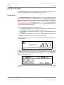
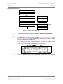
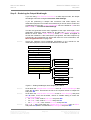
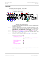
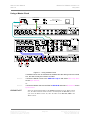
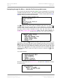
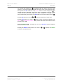
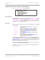
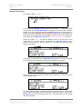
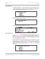
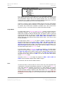
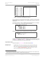
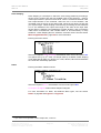
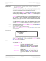
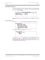
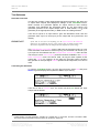
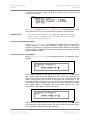
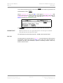
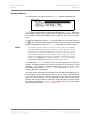
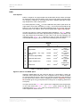
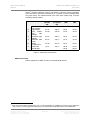
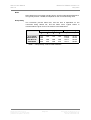
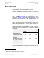
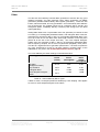
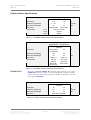
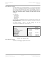
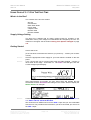
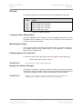
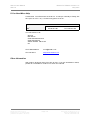
dCS 974 User Manual
dCS Ltd
Manual for Software Version 1.0x
May 2001
If Store 4 has been named Demo, the display will now look similar to this:
Press the Enter button and a message window will appear in the display to
confirm that the unit is storing the setup.
If you attempt to store a setup in a previously unused location without specifying
a name, a message window appears for two seconds, stating “First choose a
name!”.
You can name your stored setups as anything you like provided the name is no
longer than 15 characters. If you have a fixed routine, a few words may be
enough to describe the setup. If the unit is used for many different functions by
several people, we suggest using the following abbreviations to describe the
setup.
Audio Input
Input Rate
Sync source
Output Rate
Output Mode
Manual part no: DOC1241121A1
Contact dCS on + 44 1799 531 999
(inside the UK replace + 44 with 0)
use AES1, AES2, RCA, etc, DA for Dual AES, QA
for Quad AES, DSD for DSD SDIF, DSDQ for DSD
Quad.
use Au for Auto, 44 for 44.1kS/s, etc.
leave blank if synced to Audio Input or use AR for
AES Reference, MC for Multiple Channel Sync,
WC for Wordclock or Int for Internal.
use 44 for 44.1kS/s, or 2496 for 24 bits 96kS/s, or
CD for 16 bits 44.1kS/s.
leave blank for Normal, DA for Dual AES, QA for
Quad AES, DSD2 for DSD SDIF-2 or DSD3 for
DSD SDIF3.
Page 62
Document No: OS-MA-A0124-112.1A1
email to: [email protected]
web site: www.dcsltd.co.uk
dCS 974 User Manual
dCS Ltd
Manual for Software Version 1.0x
May 2001
Fixed Setups
In addition to the 12 user setups, there are 12 fixed setups which cannot be
changed. These are contained in the software and may be added to in future
software updates.
Store A
Store B
Store C
Store D
Store E
Store F
Store G
Store H
Store I
Store J
Store K
Store L
AES1 Au>24 44
Contains default settings: Auto input on AES1,
sync to Audio Input, 24 bits 44.1kS/s output in
Normal mode. If you get the unit into a tangle,
recall this and sort things out.
DA Au>CD N9 F2
Auto Dual AES input to CD format, 9th order
Noise Shaping, Filter 2, Detect silence On, Gain
set to -0.1dB.
QA Au>CD N9 F2
Auto Quad AES input to CD format, 9th order
Noise Shaping, Filter 2, Detect silence On, Gain
set to -0.1dB
DSD2>CD N9 F2
DSD SDIF-2 input to CD format, 9th order Noise
Shaping, Filter 2, Detect silence On, Gain set to
-0.1dB.
AES1 Au MC>DSD2
Auto input on AES1, Multi-Channel Sync On, to
DSD SDIF-2, Filter 5.
AES1 Au MC>24 96
Auto input on AES1, Multi-Channel Sync On, to
24/96 single wire.
AES1 Au>192DA
Auto input on AES1 to 24/192 Dual AES.
AES1 Au>DSD2 F5
Auto input on AES1 to DSD SDIF-2, Filter 5.
QA Au>DSD2 F5
Auto Quad AES input to DSD SDIF-2, Filter 5.
DA Au>24 96
Auto Dual AES input to single wire 24/96.
AES1 Au>CD N9F2
Auto input on AES1 to CD format, 9th order Noise
Shaping, Filter 2, Detect silence On, Gain set to
-0.1dB.
AES1 Au FC>DA96
Auto (96kS/s) input on AES1 to Dual 24/96,
Format Conversion On.
Recalling a Setup
Stored setups may be recalled from memory at any time. Press the Recall
button once to display the list of user-defined setups:
Manual part no: DOC1241121A1
Contact dCS on + 44 1799 531 999
(inside the UK replace + 44 with 0)
Page 63
Document No: OS-MA-A0124-112.1A1
email to: [email protected]
web site: www.dcsltd.co.uk
dCS 974 User Manual
dCS Ltd
Manual for Software Version 1.0x
May 2001
Either select one of these or press the Recall button again to toggle between
the user-defined and fixed setups:
Scroll up or down to the required store and press the Enter button. A message
window will appear in the display to confirm that the unit is reading the setup.
When complete, the display shows the Status screen for the current menu.
If you make a mistake during a Store or Recall routine and you have not yet
pressed Enter, you can abort it by pressing any of the 4 Operation buttons.
Locking Out Changes, and Unlocking Again
Once the unit is set up, it may be locked against casual interference by holding
down the Status button and pressing the Store button.
appears on the right hand side of the Status, Error Monitor, Test
Mode, Info, Bit Activity Monitor or Level Meter screen as appropriate and the
front panel controls have no effect.
To restore normal operation, hold down the Status button and press the Edit
button. The
label will disappear and normal operation will be
resumed.
Manual part no: DOC1241121A1
Contact dCS on + 44 1799 531 999
(inside the UK replace + 44 with 0)
Page 64
Document No: OS-MA-A0124-112.1A1
email to: [email protected]
web site: www.dcsltd.co.uk
dCS 974 User Manual
dCS Ltd
Manual part no: DOC1241121A1
Contact dCS on + 44 1799 531 999
(inside the UK replace + 44 with 0)
Manual for Software Version 1.0x
May 2001
Page 65
Document No: OS-MA-A0124-112.1A1
email to: [email protected]
web site: www.dcsltd.co.uk
dCS 974 User Manual
dCS Ltd
Manual for Software Version 1.0x
May 2001
THE HARDWARE – CONTROLS AND CONNECTORS
Rear Panel
PUSH
AES / EBU REFERENCE LOOP
PUSH
PUSH
PUSH
SPDIF
IN
CH1 IN
CH2 IN
REMOTE
dCS 974
[email protected]
OUT
IN
WCLK IN
LOOP OUT
CH1 OUT
CH2 OUT
LOOP IN
WCLK OUT
AES 1
AES 2
AES 3
AES 4
OUT
AES CLK OUT
SYNC INPUT
BNC
DSD / SDIF
RCA
IN
LOOP
OUT
Disconnect mains
before removing cover.
See User Manual for
installation instructions
before connecting supply.
WARNING: This unit
MUST be earthed.
MAINS FUSE (2AT)
ON OFF
V 50/60Hz 20W
AES / EBU INPUTS
PUSH
TOS
See base for
serial number
AES / EBU OUTPUTS
Figure 17– Rear Panel
All input and output connectors are mounted on the rear panel. Individual
connectors are identified by the panel legend.
Signal Inputs
AES/EBU Digital Inputs
3 pin XLR Female (4 off – AES 1 – AES 4)
Used for AES3 format signals. AES 1 and AES 2 are used together in Dual
AES mode. All four inputs are used together for Quad AES or DSD Quad
modes.
AES/EBU Reference Loop
3 pin XLR Female / Male (AES Ref Loop IN & OUT)
Loop IN is used for AES3 references and also for Sync Link operation in multichannel synchronising. Loop OUT is hard-wired to Loop IN, allowing the
reference to be daisy-chained through several units.
Sync Input
BNC
This is intended for future enhancements.
SPDIF Inputs
Various (3 off – RCA IN, BNC IN, TOS IN)
Used for SPDIF inputs. Pull the plastic dust cover out of the TOS input before
use.
DSD/SDIF Input
BNC (4 off – CH1 IN, CH2 IN, WCLK IN, LOOP OUT)
The upper group of four DSD/SDIF connectors form an input interface. They are
used as a set for SDIF-2 (PCM or DSD) or SDIF-3 (DSD only).
WCLK IN may be used to sync the unit to an external reference wordclock
while taking data from another input. WCLK IN is internally wired to LOOP
OUT, allowing a reference wordclock to be daisy-chained through several units.
When the daisy-chain is not used, the LOOP OUT connector must be fitted with
a 75Ω BNC terminator. WCLK IN will also accept a 10 MHz GPS reference.
Manual part no: DOC1241121A1
Contact dCS on + 44 1799 531 999
(inside the UK replace + 44 with 0)
Page 66
Document No: OS-MA-A0124-112.1A1
email to: [email protected]
web site: www.dcsltd.co.uk
dCS 974 User Manual
dCS Ltd
Manual for Software Version 1.0x
May 2001
Signal Outputs
AES/EBU Digital Outputs
3 pin XLR Male (4 off – AES 1, AES 2, AES 3, AES 4)
Used for AES3 format signals. AES 1 and AES 2 (or AES 3 and AES 4) are
used together in Dual AES mode. All four outputs are used together for Quad
AES or DSD Quad modes. In single AES modes, AES 2, AES 3 and AES 4
outputs follow the AES 1 output.
AES/EBU Clock Output
3 pin XLR Male (1 off – AES CLK OUT)
AES CLK OUT carries an AES3 clock signal at the same sample rate as the
AES 1 output. It is used for synchronising equipment connected to the outputs
of the unit.
SPDIF Outputs
Various (3 off - RCA OUT, BNC OUT, TOS OUT)
Used for SPDIF outputs. Pull the plastic dust cover out of the TOS output before
use.
DSD/SDIF Output
BNC (3 off – CH1 OUT, CH2 OUT, WCLK OUT)
The lower group of three DSD/SDIF connectors form an output interface. Used
as a set for SDIF-2 (PCM or DSD) or SDIF-3 (DSD only) outputs.
WCLK OUT carries Wordclock at the same rate as that appearing on the AES 1
output. It may be used to synchronise equipment connected to any of the dCS
974 data outputs.
(The lower LOOP IN connector is intended for future enhancements.)
Control and Power
Remote
9 pin D type Female (2 off, Remote In and Loop Out)
For remote control via a PC, and/or downloading software updates. Remote In
and Loop Out sockets allow daisy chaining of several different dCS units from
one PC COM port.
Mains Supply
3 pin IEC (CEE22)
Switched, fused and filtered IEC power inlet, for a 50 or 60 Hz AC supply.
Additional Information
As well as connectors, the rear panel displays the following information about
the unit, near the mains supply connector:
Mains Voltage
The actual voltage setting supplied.
Model Number
dCS 974
Manufacturers Name and Country of origin (dCS Ltd, UK)
The underside of the unit will have a label on that contains a number such as
974-4B1-6B2-2A1-3A2-12345. This is the unit serial number, but it also contains
vital configuration information. We will need this number (all of it) to give you
support over the phone, or to ship software updates to you.
Manual part no: DOC1241121A1
Contact dCS on + 44 1799 531 999
(inside the UK replace + 44 with 0)
Page 67
Document No: OS-MA-A0124-112.1A1
email to: [email protected]
web site: www.dcsltd.co.uk
dCS 974 User Manual
dCS Ltd
Manual for Software Version 1.0x
May 2001
Front Panel
BIT
24
192kS/s
OPERATION
Status
Set
Dither
Power
Noise shaping
L/R flip
DSD
MEMORY
Direct Stream Digital
Recall
Edit
Store
Phase
Enter
Gain
Balance
Unlocked
dCS 974 D to D Converter
dC S
Data Conversion Systems
Figure 18 – Front Panel
Because of the many options on the dCS 974, we have used a menu based
system to control it. The hardware buttons and knobs below navigate you
through it.
Power Indicator
The LED in the top left hand corner lights when power is applied.
OPERATION buttons
The bank of 4 buttons in the top left hand corner are the Operation buttons and
are used for navigating around the menu tree:
Status
←
→
Set
returns the display to the status information screen
to allow a rapid check of key settings.
selects the previous (higher) menu level.
selects the next (lower) menu level.
implements the selected menu item.
MEMORY buttons
The bank of 4 buttons in the lower left hand corner are the Memory buttons and
are used for storing and retrieving setups:
Recall
Store
Edit
Enter
allows one of ten stored setups to be selected
ready for loading.
allows one of ten locations to be selected as the
location for saving the current setup.
is used to change the name of a saved setup.
loads or saves a setup.
LCD display
The backlit LCD display in the centre of the panel can display up to 8 lines of
information.
Manual part no: DOC1241121A1
Contact dCS on + 44 1799 531 999
(inside the UK replace + 44 with 0)
Page 68
Document No: OS-MA-A0124-112.1A1
email to: [email protected]
web site: www.dcsltd.co.uk
dCS 974 User Manual
dCS Ltd
Manual for Software Version 1.0x
May 2001
LED indicators
A group of LED indicators to the right of the LCD display gives a level of status
indication:
Dither
Noise shaping
L/R flip
Two Phase LEDs
Gain
Balance
Unlocked
is lit if any Dither is selected.
is lit if any Noise Shaping is selected.
indicates that the channels are flipped.
indicate if either or both channels are phase
inverted.
is lit if the setting is other than unity gain (i.e. 0dB).
is lit if the channel balance is shifted from centre.
is lit if the unit is not locked to a valid digital input.
Rotary encoder
Turn the knob to move up down the menu tree, adjust parameter values or edit
store names. You may select whether clockwise rotation moves the cursor up or
down - see the section on Display Customise, page 50. The unit is shipped
with the cursor moving downwards by clockwise rotation of the knob and all
instructions in this manual refer to a unit in this configuration. We recommend
turning the knob at a steady speed, rather than trying to turn it as fast as
possible.
Manual part no: DOC1241121A1
Contact dCS on + 44 1799 531 999
(inside the UK replace + 44 with 0)
Page 69
Document No: OS-MA-A0124-112.1A1
email to: [email protected]
web site: www.dcsltd.co.uk
dCS 974 User Manual
dCS Ltd
Manual for Software Version 1.0x
May 2001
dCS 974 TECHNICAL INFORMATION
Digital Data Formats Supported
dCS 974 provides nine digital data i/o formats:
AES/EBU
Dual AES
Quad AES
SDIF-2
SDIF-2
SDIF-3
DSD Quad
SPDIF
SPDIF
(often referred to as AES3) for PCM operation
(part of the AES3 spec) for PCM operation
for PCM operation
for DSD operation
for DSD operation
for DSD operation
(electrical) for PCM operation
(optical) for PCM operation
For all formats, the incoming Channel Status and User messages are
12
discarded . The unit allows the AES/EBU and SPDIF output Channel Status
bits to be edited.
The enhanced AES/EBU interface is fully implemented. Each channel has its
own parity and data validity bit, as well as User and Channel Status messages.
Cyclic Redundancy Counts (CRC's) are generated from the Channel Status
message.
The Dual AES interface allows an 88.2 or 96kS/s 24 bit signal to be coded as
two standard 44.1 or 48kS/s 24 bit AES data streams, recorded as four tracks
on a recorder with standard capacity, replayed and decoded back into a single
data stream. Operation of the Dual AES interface at double speed allows the
unit to input or output 2 wire 176.4 or 192 kS/s 24 bit data, and convert to and
from this.
The Quad AES interface allows an 176.4 or 192kS/s 24 bit Dual AES data
stream to be coded as four standard 44.1 or 48kS/s 24 bit AES data streams,
recorded as eight tracks on a recorder with standard capacity. It may be
replayed and converted into a Dual AES stream, a single wire format or DSD.
SDIF-2 PCM message bits are internally set to zero, with the exception of the
block code, which is implemented.
The SPDIF interface has no CRC's - as per definition. Data formats for both
SPDIF electrical and SPDIF optical are identical.
DSD has, at the time of writing, no messaging structure. Contact dCS for more
details. Data formats use either the SDIF-2 system (two data channels and
third clock channel), the SDIF-3 format (two data channels with embedded
clock) or the DSD Quad format (four AES3 style data streams).
12
At present we do this because there is no standard on what to do with the excess or shortage of bits that is
created by a sample rate change. If this causes you a problem, call us – we can probably do something else,
if we are clear what that ought to be.
Manual part no: DOC1241121A1
Contact dCS on + 44 1799 531 999
(inside the UK replace + 44 with 0)
Page 70
Document No: OS-MA-A0124-112.1A1
email to: [email protected]
web site: www.dcsltd.co.uk
dCS 974 User Manual
dCS Ltd
Manual for Software Version 1.0x
May 2001
DSD
Filter Options
DSD is a single bit very high sample rate (2.822 MS/s) format, where the single
bit words are heavily noise shaped to push noise energy above the audio band.
The frequency response is very high (well above 100 kHz) although at these
high frequencies, noise is also present.
For SACD purposes, 0 dB0DSD is set at 6 dB below the peak to peak level one
might expect a full scale sinewave to occupy – this ensures that artefacts that
begin to occur at the limits of the DSD amplitude range do not move down into
the audio band. The 0 dB0DSD level is shown graphically in Figure 39, page 98.
The dCS 974 offers a number of different DSD modulators – as Filter options.
All the modulators have the same signal frequency response. They differ in the
way they shape the out-of-band Q noise, and in how far they suppress the
in-band Q noise. Filters 1 to 5 suppress Q noise at least 120 dB below the
nominal 0dB DSD signal, which is one of the marketing specs for SACD.
Filter
Comments
SQNR
(20 kHz,
dB)
Stability
1
High SQNR, high stability
126.14
1.7*10
2
High SQNR
127.23
8.2*10
3
124.66
1.5*10
4
High SQNR, very high
stability
Extremely high stability
122.07
3.0*10
5
Reduced 100k noise
122.27
7.1*10
6
Single complex zero
110.78
3.7*10
7
Real zeros
101.5
2.0*10
10
8
11
12
10
11
10
Description
Two complex
zeros
Two complex
zeros
Two complex
zeros
Two complex
zeros
Two complex
zeros
Single
complex zero
Real zeros
only
Table 4 – DSD Filter Summary
Signal to Q Noise and SACD Specs
Although 120dB SNR over the 0-20 kHz band is a good target, it does not
match the ears response that well. The F weighted curve is currently accepted
as a good model for the ear, and we can use this to weight the noise produced
by the various filter choices. Such a weighting is shown in Figure 38 on page
98, and DSD gives very good performance using such a weighting (better than
23 bit pcm)
The figure shows that Filter 6 and 7 give more F weighted Q noise suppression
in the audio band than Filters 1 to 5. Filter 6 gives around 20 dB more
suppression than Filters 1 to 5 under all circumstances and Filter 7 gives 20dB
more suppression below 10 kHz.
Manual part no: DOC1241121A1
Contact dCS on + 44 1799 531 999
(inside the UK replace + 44 with 0)
Page 71
Document No: OS-MA-A0124-112.1A1
email to: [email protected]
web site: www.dcsltd.co.uk
dCS 974 User Manual
dCS Ltd
Manual for Software Version 1.0x
May 2001
13
SACD specifies ultrasonic noise in two bands. These are specs informative
specs E2 and E3, and filter performance for a number of specs including these
are given below. The measurements given have been made using a Fourier
Transform based method.
Filter
Comments
SQNR
(20 kHz,
dB)
SQNR
(F weighted
dB)
1
High
SQNR,
high stability
High SQNR
High
SQNR,
very
high
stability
Extremely high
stability
Reduced 100k
noise
Single
complex zero
Real zeros
SACD Spec
126.14
-136.56
-25.98
-28.96
127.23
124.66
-138.76
-134.38
-25.85
-27.32
-28.95
-30.49
122.07
-129.91
-25.54
-29.53
122.27
-130.14
-27.13
-31.99
110.78
-151.02
-25.19
-23.55
101.5
-132.41
-25.29
-20.00
-27.04
-28.00
2
3
4
5
6
7
E2 spec
(dB)
E3 spec
(dB)
Table 5 – DSD Filter Performance
DSD Data Formats
DSD is supported on SDIF-2, SDIF-3 and DSD Quad formats.
13
Super Audio CD System Specifications, Part 2, Audio Specifications, available from Philips System Standards
and Licensing, Licensing Support, Building SFF-8, PO Box 80002, 5600 JB Eindhoven, The Netherlands.
Manual part no: DOC1241121A1
Contact dCS on + 44 1799 531 999
(inside the UK replace + 44 with 0)
Page 72
Document No: OS-MA-A0124-112.1A1
email to: [email protected]
web site: www.dcsltd.co.uk
dCS 974 User Manual
dCS Ltd
Manual for Software Version 1.0x
May 2001
PCM Input and/or Output Performance
Filtering
The normal filtering considerations of passband ripple, cutoff frequency and
rate, out of band (stop band) suppression, and transient/phase response apply
to sample rate converters.
The dCS 974 uses linear phase FIR filters to avoid the limit cycle problems that
come with many IIR filters. Linear phase gives filters a symmetrical transient
response before and after a transient (“pre-ringing” and “post ringing”). The
14
passband may or may not have a ripple , depending on the conversion and/or
filter being used. Cutoff frequency is >40% of the lowest sampling rate used in
15
the conversion (input or output).
The stop band is typically below –110 dB,
but varies with conversion, and can be as low as –130 dB. The frequency
responses of two commonly used conversions (96kS/s ⇒ 44.1kS/s and 48kS/s
⇒ 44.1kS/s) are shown in Figure 41 and Figure 40 on page 99.
The transient responses of the filters in the 96 kS/s ⇒ 44.1 kS/s conversion are
shown below.
Figure 19 – Transient Performance of 44.1 kS/s Filter Options
Use of higher sample rates gives much tighter transient response, with much
less energy smeared into the pre and post ringing. The transient responses of
the 96 kS/s output filters are shown below:
14
15
Filters always have some ripple. For “zero ripple” filters this is in the µdB to pdB region.
For conversions where the lowest rate used is 16 kS/s, 22.05 kS/s or 24 kS/s some conversions cut off at 33%
of the lowest sample rate.
Manual part no: DOC1241121A1
Contact dCS on + 44 1799 531 999
(inside the UK replace + 44 with 0)
Page 73
Document No: OS-MA-A0124-112.1A1
email to: [email protected]
web site: www.dcsltd.co.uk
dCS 974 User Manual
dCS Ltd
Manual for Software Version 1.0x
May 2001
Figure 20 – Transient Performance of 96 kS/s Filter Options
Spurs
Sample rate conversion is a linear process, so spurs are not caused by
16
mechanisms that produce harmonic distortion. Spurs are caused by high order
17
images of the baseband input signal aliasing back into the output . The filtering
in the converter has to suppress these.
We measure these spurs for a 1 kHz input signal – typical values are given in
dB0 for a -1dB0 sine wave in the table below. The blank cells are two pass
conversions, where the performance depends on both conversions.
Input
Rate
(kS/s) 11.02
5
Output Sample Rate (kS/s)
12
16
22.05
24
11.025
-130
-122
-143
-117
12
-139
-136
-131
-135
-132
-119
-132
16
32
44.1
48
-136
-119
88.2
96
-137
-112
-130
-137
-137
-145
-124
-134
-130
-134
-113
24
-121
-134
-127
-142
-137
-128
-129
-133
-123
-131
-107
-134
44.1
-132
-120
-124
-133
-145
-125
-136
-126
-127
-109
48
-118
-132
-136
-119
-134
-125
-137
-136
-127
-130
88.2
-129
-120
-119
-135
-120
-125
-137
-145
-139
-121
96
-97
-126
-138
-116
-135
-139
-117
-137
-119
-139
-128
176.4
-137
192
-128
192
-132
-119
-140
-138
22.05
32
176.4
-139
-134
-134
-130
-139
-132
-117
-105
-117
-135
-131
-135
Table 6 – Typical Spurious Level vs Conversion
16
17
Spurious products
For example, a 1 kHz tone with a 48 kS/s sample rate in will produce spurs at 2.9 kHz and 4.9 kHz, 6.8 kHz
and 8.8 kHz, etc, with a 44.1 kS/s sample rate out.
Manual part no: DOC1241121A1
Contact dCS on + 44 1799 531 999
(inside the UK replace + 44 with 0)
Page 74
Document No: OS-MA-A0124-112.1A1
email to: [email protected]
web site: www.dcsltd.co.uk
dCS 974 User Manual
dCS Ltd
Manual for Software Version 1.0x
May 2001
Noise
Noise arises from processing rounding errors, and from stop band performance.
It is typically around –130dB0, but depends on the conversion being used.
Group Delay
The conversion process takes time, and the time is dependent on the
conversion being carried out, and the filters used. Typical values in
microseconds are given for four conversions in the table below.
Conversion
Filter
1
44.1k ⇒ 96k
88.2k ⇒ 44.1k
96k ⇒ 44.1k
96k ⇒ 48k
1141
1024
1515
868
Group Delay (µ
µs)
Filter
Filter
Filter
2
3
4
1131
1131
1131
1065
958
1065
1028
1065
948
Sample Period (µ
µs)
Input
Output
22.676
11.338
10.417
10.417
10.417
22.676
22.676
20.833
Table 7 – Group Delays, PCM to PCM transitions
Manual part no: DOC1241121A1
Contact dCS on + 44 1799 531 999
(inside the UK replace + 44 with 0)
Page 75
Document No: OS-MA-A0124-112.1A1
email to: [email protected]
web site: www.dcsltd.co.uk
dCS 974 User Manual
dCS Ltd
Manual for Software Version 1.0x
May 2001
Clocking
The sample clock quality significantly determines the output performance of a
DDC, in as far as items connected may have to reconstitute an analogue signal,
and may ultimately derive their clock from the DDC clock.
The highest quality clocks that are available are crystals, so we use these. In
Internal sync mode, the dCS 974 uses one of two on-board voltage controlled
crystal oscillators (VCXOs) as clock sources – one for 48 kS/s related outputs
and one for 44.1 kS/s related outputs.
The internal VCXO is synchronised to the sync source (which need not be the
signal input) by a phase locked loop (PLL). The PLL is of a special narrow
bandwidth type, that provides a significant degree of "clock cleaning" - but even
so, signal quality may degrade if particularly poor slave clocks are used. A
consequence of the narrow bandwidth is that it takes quite a long time for the
PLL to lock to a new clock frequency – of the order of 2 seconds. The PLL uses
DSP assistance to keep this time acceptable.
The input data is extracted using an oversampled UART type of decoder. This
can tolerate quite jittery inputs, whose phase is unrelated to the clock source
used for locking. The average frequency must be the same, however.
Internal clock
Accuracy when shipped
Long Term Stability
Temperature Stability
± 10 ppm
± 10 ppm/year at room temperature
± 15 ppm over operating temperature range
Synchronising to source
Pull in range
Lock in time
± 300 ppm about nominal frequency
< 2 seconds for most combinations
The PLL is very robust, and will lock to very poor signals if necessary. Data is
decoded using a much wider band (faster) PLL, so AES3 type low frequency
jitter on the input clock can be handled, and will be cleaned.
If you need to synchronise several items of digital equipment, we recommend
using a dCS 992 Master Clock.
Manual part no: DOC1241121A1
Contact dCS on + 44 1799 531 999
(inside the UK replace + 44 with 0)
Page 76
Document No: OS-MA-A0124-112.1A1
email to: [email protected]
web site: www.dcsltd.co.uk
dCS 974 User Manual
dCS Ltd
Manual for Software Version 1.0x
May 2001
Sample Alignment
The dCS 974 aligns samples such that SDIF WCLK OUT aligns with AES3
samples out, the rising edge of wordclock aligning with the start of the first
illegal code in the X,Z subframe preamble and the falling edge aligning with the
start of the Y subframe preamble.
Figure 21 – Wordclock and AES3 outputs, 96 kS/s
Figure 22 – Wordclock and AES3 outputs, 44.1 kS/s
Manual part no: DOC1241121A1
Contact dCS on + 44 1799 531 999
(inside the UK replace + 44 with 0)
Page 77
Document No: OS-MA-A0124-112.1A1
email to: [email protected]
web site: www.dcsltd.co.uk
dCS 974 User Manual
dCS Ltd
Manual for Software Version 1.0x
May 2001
When SDIF WCLK IN is used as a sync source, in and out are related as
18
For
below. The lower waveform is the output, the upper one is the input.
44.1 kS/s, out leads in by about 500 ns, and for 96 kS/s it is about 230 ns.
Figure 23 – Wordclock in to Wordclock out, 96 kS/s
Figure 24 – Wordclock in to Wordclock out, 44.1 kS/s
If tighter alignment of WCLK IN to WCLK OUT is needed, consider using a
dCS 992 Master Clock, where the phase of individual word clock feeds is
adjustable, or contact us.
18
If this misalignment causes you a problem, please contact us.
Manual part no: DOC1241121A1
Contact dCS on + 44 1799 531 999
(inside the UK replace + 44 with 0)
Page 78
Document No: OS-MA-A0124-112.1A1
email to: [email protected]
web site: www.dcsltd.co.uk
dCS 974 User Manual
dCS Ltd
Manual for Software Version 1.0x
May 2001
AES3 in and out are related as below, where they are at the same sample rate,
and the AES3 input is used as a sync source. The alignment is better than
40ns. Input is at the top of the displays, output is at the bottom. Signals are at
the sockets on the dCS 974.
Figure 25 – AES3 in to AES3 out, 96 kS/s
Figure 26 – AES3 in to AES3 out, 44.1 kS/s
Manual part no: DOC1241121A1
Contact dCS on + 44 1799 531 999
(inside the UK replace + 44 with 0)
Page 79
Document No: OS-MA-A0124-112.1A1
email to: [email protected]
web site: www.dcsltd.co.uk
dCS 974 User Manual
dCS Ltd
Manual for Software Version 1.0x
May 2001
DSD data out is aligned to Wordclock transitions, as below – the wordclock
edges align with the data transitions, rather than in the middle of the data eye.
If you need them the other way round, use an additional 10m of cable in the
WCLK OUT path.
Figure 27 – DSD data and Wordclock out
Manual part no: DOC1241121A1
Contact dCS on + 44 1799 531 999
(inside the UK replace + 44 with 0)
Page 80
Document No: OS-MA-A0124-112.1A1
email to: [email protected]
web site: www.dcsltd.co.uk
dCS 974 User Manual
dCS Ltd
Manual for Software Version 1.0x
May 2001
Multiple Channel Sync’ing
Multiple channel sync’ing requires more things to be in sync than two channel
work - the PLL must not be dual modulus, the DSP algorithm must load with a
constant group delay, and the frame and block syncs must agree.
The dCS 974 meets all these constraints with the addition of a syncing signal
transmitted from a master unit to subsequent slave units. To do this, it passes
information in the User Bits of the AES3 message. To slave adequately, units
must have this sync information input to the AES Ref Loop Input, via a sync
link. Each slave will generate a copy, based on its own timing, for transmission
to the next unit in the chain. If the Multi-channel Sync option is set to On in the
Sample Rate Conversion menu, any units with no user bit synchronisation
data into its AES Ref Loop Input will become a Master. If user bit
synchronisation information is fed in, it will become a slave. Either unit will
output synchronisation information via its AES CLK Output. A master clock
19
(dCS 992 ) can be used as the master – if more than about 8 channels are
being used, this system is best, as it avoids any tolerance build up. Connections
are shown in the multi-channel syncing applications, starting on page 29.
Using the multi-channel sync mode, the timing of the data at the output of the
dCS 974 is related to the data coming in. If three dCS 974 units are used in a six
channel set up, and the data into all of them is bit sync’d from (say) a six
channel source, the outputs will be bit sync’d. If the inputs are not quite bit
aligned, then the outputs will not quite be bit aligned. If the inputs are way off in
phase but frequency locked, the outputs will be way off in phase but frequency
locked, and the timing of the block structures of the several output signals will
not be defined.
Sample Rate (kS/s)
Time in
input
sample
20
rate UI’s
± 0.3
Time in ns,
44.1 kS/s
input
Time in ns,
96 kS/s
input
Basic dCS 974 unit to unit
± 50
± 24
output timing alignment.
Input misalignment allowed,
±2
± 334
± 162
with all inputs at the same
frequency,
for
block
structuring to work (no
Master Clock).
Input misalignment allowed,
±4
± 668
± 324
with all inputs at the same
frequency, with Master Clock
± 64
± 11338
± 5208
Input misalignment allowed,
with all inputs at the same
frequency, with Master Clock
21
as in Figure 16 .
Table 8 – Multiple Channel Sync mode – allowable input misalignment
The scope shots below show the timing relationships between two units, using
the sync link, for various conversions. They are taken from 2 units, with scope
probes on the same point in each unit. The units are linked by a sync link.
19
20
21
version 2.0 software or higher.
UI = Unit Interval, see AES3 spec. There are 128 UI’s per sample in AES3.
Master Clock can adjust its Wordclock phases as necessary.
Manual part no: DOC1241121A1
Contact dCS on + 44 1799 531 999
(inside the UK replace + 44 with 0)
Page 81
Document No: OS-MA-A0124-112.1A1
email to: [email protected]
web site: www.dcsltd.co.uk
dCS 974 User Manual
dCS Ltd
Manual for Software Version 1.0x
May 2001
Figure 28 – 44.1 kS/s to 96 kS/s PCM, showing AES3 alignment
Figure 29 – 96 kS/s to 44.1 kS/s PCM, showing AES3 alignment
Manual part no: DOC1241121A1
Contact dCS on + 44 1799 531 999
(inside the UK replace + 44 with 0)
Page 82
Document No: OS-MA-A0124-112.1A1
email to: [email protected]
web site: www.dcsltd.co.uk
dCS 974 User Manual
dCS Ltd
Manual for Software Version 1.0x
May 2001
Figure 30 – 44.1 kS/s to DSD, showing DSD bit alignment
Multiple Channel Multiple Sample Rate Synchronising
DVDs can make use of mixed sample rates in their multi-channel mode – for
example, 96 kS/s in the front channels and 48 kS/s in the rear channels.
As well as the problems mentioned above in the section Multiple Channel
Sync’ing, use of multiple channels brings an additional problem in that the
group delay in the sample rate conversion process varies with the sample rate.
It generally gets longer as the sample rate gets lower, making the rear channels
seem further away than you might want.
Figure 16 shows how a master clock may be used with several dCS 974‘s in
parallel to get simultaneous synchronised sample rates out at the same time.
Please contact dCS if you need support for this process.
Manual part no: DOC1241121A1
Contact dCS on + 44 1799 531 999
(inside the UK replace + 44 with 0)
Page 83
Document No: OS-MA-A0124-112.1A1
email to: [email protected]
web site: www.dcsltd.co.uk
dCS 974 User Manual
dCS Ltd
Manual for Software Version 1.0x
May 2001
Noise Shaping
22
23
The dCS 974 uses noise shaping that is optimised to the F weighting curve .
It does not affect signal frequency or transient response, but shapes the
frequency response of errors (Q noise, or truncation errors) so that they fall as
much as possible in the less sensitive part of the spectrum. The architecture
used also shapes dither, where this is added. For all the major sample rates
(32 kS/s, 44.1 kS/s, 48 kS/s, 88.2 kS/s, 96 kS/s) the noise shapers have been
st
rd
th
individually optimised and the first 10 orders are offered. The 1 , 3 , and 9
24
shapes for 44.1 kS/s agree well with Wannamaker’s published results .
Noise Shaping adds more noise power, but because of the shaping it is
perceived as lower noise. There is a compromise to be drawn – as more
aggressive shaping is used, more noise is added, and less perceived
th
improvement occurs. In practice, things stop improving by about the 10 order.
The increased real noise power can cause (small) clicks in editing, if this is
carried out after the shaping. For each major sample rate, we recommend an
aggressive and a gentle setting, below:
Sample Rate
(kS/s)
32
44.1
48
88.2
96
Lowest
Order
st
1
st
1
st
1
st
1
st
1
Highest
Order
th
10
th
10
th
10
th
10
th
10
Gentle
Shaping
nd
2
nd
2
nd
2
rd
3
rd
3
Aggressive
Shaping
th
6
th
9
th
8
th
7
th
7
Table 9 – Noise Shape Orders by Output Sample Rate
The gentle shaping tends to follow the E weighting curve, by chance. For more
information on this topic, either see Word Length Reduction on page 104 or
read the references below.
22
23
24
It actually uses an Error Shaping architecture, but the name is now being used for entirely other things and is
less well known, so we call it, erroneously, Noise Shaping
“Minimally Audible Noise Shaping”, S.P.Lipshitz and R.A.Wannamaker, J AES vol 39 no 11, p836-852
“Psychacoustically Optimal Noise Shaping”, R.A.Wannamaker, J AES vol 40 no 7/8, p611-620
Manual part no: DOC1241121A1
Contact dCS on + 44 1799 531 999
(inside the UK replace + 44 with 0)
Page 84
Document No: OS-MA-A0124-112.1A1
email to: [email protected]
web site: www.dcsltd.co.uk
dCS 974 User Manual
dCS Ltd
Manual for Software Version 1.0x
May 2001
Dither
The dCS 974 uses relatively unusual dither generators to achieve the very good
statistics necessary for audio purposes. Many dither generators use PRBS
generators (Pseudo Random Binary Shift register generators). These are well
known, well documented, and very predictable – but unfortunately their statistics
are not that great. The problem shows up as a spectrum that is not flat, and
histograms (PDFs, Probability Density Functions) that diverge from the ideal
quite significantly.
Adding dither adds noise. Top hat dither uses one generator per channel to add
±0.5 lsbs p-p of rectangularly distributed dither, and triangular dither uses two
generators per channel to add ±1 lsbs p-p of triangularly distributed dither. This
is on top of the Q/√12 rms dither from word length reduction in the first place
(where Q is the size of the output word lsb). The noise shaped triangular
setting uses one generator to add ±1 lsbs p-p of triangularly distributed dither
that is frequency shaped, and so has low perceived (weighted) noise power.
This last is a significant test of generator performance – the dCS 974 performs
very well. Performance curves for all these settings, including PDFs of the
added dither, are given in the dCS 974 Performance Curves, page 94.
The noise added by the dither settings is summarised below:
Dither Type
No dither
(straight truncation)
Top Hat dither
Triangular dither
Noise Shaped Triangular
dither
Noise
Power
(0-Fs/2)
Added Noise
Power
(unweighted)
Q/√12
0 dB
Perceived
Noise
Added
(F weighted)
0 dB
Q/√6
Q/√4
Q/√4
3 dB
4.8 dB
4.8 dB
3 dB
4.8 dB
1.2 dB
Table 10 – Noise Added by Dither Types
If dither is used, it is shaped (made less audible) by noise shaping. This applies
as much to noise shaped triangular as the others.
Manual part no: DOC1241121A1
Contact dCS on + 44 1799 531 999
(inside the UK replace + 44 with 0)
Page 85
Document No: OS-MA-A0124-112.1A1
email to: [email protected]
web site: www.dcsltd.co.uk
dCS 974 User Manual
dCS Ltd
Manual for Software Version 1.0x
May 2001
Digital Interface Specifications
AES/EBU (AES3)
Type
Impedance
Sensitivity (unloaded)
Maximum Wordlength
Connector
Connections
Pin 1
Pin 2
Pin 3
Input
Output
Balanced, differential
110
110
1 ~ 10
7
24
24
XLR3 female
XLR3 male
Ground or shield
+Signal
-Signal
Ω
V pk-pk
bits
Table 11 – AES/EBU Interface Electrical Characteristics.
SDIF and DSD
Input
Output
(Upper block) (Lower block)
Single ended, ground
referred
100 (CH1/2)
55
~1k (WCLK)
TTL
TTL
24
24
BNC x 4
BNC x 3
CH1 IN
CH1 OUT
CH2 IN
CH2 OUT
WCLK IN /
WCLK OUT
LOOP OUT
Type
Impedance
Sensitivity (unloaded)
Maximum Wordlength
Connector
Connections
Ω
bits
Table 12 – DSD/SDIF Interface Electrical Characteristics.
IMPORTANT!
The upper DSD/SDIF WCLK IN connector loops through to the upper
LOOP OUT connector to allow an external Wordclock to be daisy-chained.
The last unit in the daisy-chain will need a 75Ω BNC termination connected
to the upper LOOP OUT.
SPDIF (electrical)
Type
Input
Output
Single ended, ground
referred
75
75
0.5
1.0
24
24
RCA Phono & BNC
Impedance
Sensitivity (unloaded)
Maximum Wordlength
Connector
Ω
V pk-pk
bits
Table 13 – SPDIF Interface Electrical Characteristics.
Manual part no: DOC1241121A1
Contact dCS on + 44 1799 531 999
(inside the UK replace + 44 with 0)
Page 86
Document No: OS-MA-A0124-112.1A1
email to: [email protected]
web site: www.dcsltd.co.uk
dCS 974 User Manual
dCS Ltd
Manual for Software Version 1.0x
May 2001
SPDIF (optical)
Type
Maximum Wordlength
Wavelength
Connector
Input
Output
Optical
24
24
660nm
Toslink EIAJ CP-340
bits
Table 14 – SPDIF Optical Interface Characteristics.
IMPORTANT!
The Toslink interface is not specified for operation at 88.2 or 96 kS/s due to
limitations in the Toslink devices. In practice, the interface has been shown
to operate correctly with other dCS equipment at all sample rates up to
96kS/s but dCS cannot guarantee this due to Toslink manufacturing
variations.
Manual part no: DOC1241121A1
Contact dCS on + 44 1799 531 999
(inside the UK replace + 44 with 0)
Page 87
Document No: OS-MA-A0124-112.1A1
email to: [email protected]
web site: www.dcsltd.co.uk
dCS 974 User Manual
dCS Ltd
Manual for Software Version 1.0x
May 2001
Message Handling
The dCS 974 strips the message information from the incoming data. The
message in the outgoing data is set using the AES Message Edit and SPDIF
Message Edit menus, located under the Sample Rate Conversion menu.
AES/EBU Message Handling
The AES3-1992 standard was written at a time when only 3 sample rates were
in common use in the audio industry. dCS started manufacture of ADCs
featuring 96 and 88.2 kS/s sample rates in 1993 and we have evolved
modifications to AES3-1992 which accommodate these innovations. These are
currently being considered by the AES.
The AES/EBU interface transmits a data structure that conforms to the dCS
version of AES3-1992. This contains 28 bits of Manchester encoded data, and a
4 bit near-Manchester encoded preamble in a subframe, and subframes are
further assembled in a block and frame structure. Each subframe contains:
•
•
•
•
•
•
IMPORTANT!
preambles, to allow the receiver to sync up
up to 24 bits of audio data, transmitted lsb first
V, a validity bit
U, a user bit, for the "User Message"
C, a Channel Status bit, for the "System Message"
P, a parity bit
The AES/EBU interface and the SPDIF interface have similar data
structures, although the messages are completely different. The two
structures are identified in the data domain by the use of the
Consumer/Professional bit (bit 1 in the message). A "1" indicates AES/EBU
format, a "0" indicates SPDIF format.
The default AES/EBU message attached to the output data by the unit before
being changed by the user is as follows:
Professional:
Non-Audio:
Mode:
Source:
Destination:
On
Off
Stereophonic
DCS1
null
For more information on the way dCS implement the AES3 system message to
handle higher sample rates, see the Appendix to this manual. For the formal
25
definition of the AES3 interface, see footnote , from the AES.
25
AES3-1992 (ANSI S4.40-1992) “AES Recommended practice for digital audio engineering – Serial
transmission format for two-channel linearly represented digital audio data”.
Manual part no: DOC1241121A1
Contact dCS on + 44 1799 531 999
(inside the UK replace + 44 with 0)
Page 88
Document No: OS-MA-A0124-112.1A1
email to: [email protected]
web site: www.dcsltd.co.uk
dCS 974 User Manual
dCS Ltd
Manual for Software Version 1.0x
May 2001
SPDIF Message Handling
The SPDIF interface (sometimes known as the Consumer AES/EBU interface)
26
transmits a data structure that conforms to the IEC 958 standard. Like the
AES/EBU, this contains 28 bits of Manchester encoded data, and a 4 bit nearManchester encoded preamble in a subframe, and subframes are further
assembled in a block and frame structure. The difference lies only in the voltage
levels, and the Channel Status bits (the System Message). It contains 24 bits of
audio data.
IMPORTANT!
The AES/EBU interface and the SPDIF interface have similar data
structures, although the messages are completely different. The two
structures are identified in the data domain by the use of the
Consumer/Professional bit (bit 1 in the message). A "1" indicates AES/EBU
format, a "0" indicates SPDIF format.
The default SPDIF message attached to the output data by the unit before
being changed by the user is as follows:
Professional:
Non-Audio:
Copy Permit:
Format:
26
Off
Off
On
2-Channel General Format
See EN 60958:1995 or IEC 958:1989 with amendments 1&2. The structure of the message is sufficiently
complex that it is best to read the source material.
Manual part no: DOC1241121A1
Contact dCS on + 44 1799 531 999
(inside the UK replace + 44 with 0)
Page 89
Document No: OS-MA-A0124-112.1A1
email to: [email protected]
web site: www.dcsltd.co.uk
dCS 974 User Manual
dCS Ltd
Manual for Software Version 1.0x
May 2001
SDIF-2 Message Handling
The SDIF-2 interface is a 4 wire NRZ interface - so the DC level on each signal
line may not be constant. It contains 20 bits of audio data and has a block
structure of 256 stereo samples, rather than the 192 of AES/EBU. There are 8
bits of message per channel per sample - with a further 3 bits being used for an
"illegal code" based sync code. Of the 8 bits per sample, the 8 in the first
sample are reserved for system messaging, and the rest are for User
messages.
The 4 wires are:
Ground return
Left Channel
Right Channel
Wordclock
The sync codes enable data recovery without the word clock, if necessary, but
with the number of data formats in current operation, this method of locking is
strongly discouraged.
The SDIF-2 message is given in the table following. The dCS 974
implementation sets all bits of the User message to "0".
DESCRIPTION
Definition
Undefined
Emphasis
No emphasis
Emphasis (15µsec, 50µsec)
Dubbing Prohibit
Dubbing allowed
Dubbing inhibited
Block Code
Start of block
Not start of block
0000 0xxx
Default
Message
0000 0xxx
xxxx x00x
xxxx x01x
xxxx x00x
xxxx xxx0
xxxx xxx1
xxxx xxx0
xxxx xxxx 1...
xxxx xxxx 0...
as required
as required
Table 15 - SDIF-2 Message Table
SDIF-3 Message Handling
At present, no messaging is implemented in SDIF-3.
Manual part no: DOC1241121A1
Contact dCS on + 44 1799 531 999
(inside the UK replace + 44 with 0)
Page 90
Document No: OS-MA-A0124-112.1A1
email to: [email protected]
web site: www.dcsltd.co.uk
dCS 974 User Manual
dCS Ltd
Manual for Software Version 1.0x
May 2001
Power Consumption
The dCS 974 has a linear power supply, and so power consumption changes as
the supply voltage changes. The internal regulation is comparatively efficient for
a linear supply, so these changes are kept to a minimum. Consumption is
independent of supply voltage setting.
Power Consumption with Supply Voltage (measured as AC power into mains
socket):
Nominal voltage
16 W
Voltage -10%
Voltage +10%
14 W
17 W
The actual intended supply voltages are shown on the rear panel. 50Hz or 60Hz
operation is not important – the unit can use either. In general, users will not
need to change the mains input configuration. If you do need this to be done,
please see the section Having Your Options Changed, page 114 in this
manual and contact your distributor or dCS.
Manual part no: DOC1241121A1
Contact dCS on + 44 1799 531 999
(inside the UK replace + 44 with 0)
Page 91
Document No: OS-MA-A0124-112.1A1
email to: [email protected]
web site: www.dcsltd.co.uk
dCS 974 User Manual
dCS Ltd
Manual for Software Version 1.0x
May 2001
Size, Weight and Operating Conditions
Size and Weight
The dCS 974 dimensions correspond to a standard 2U 19" rack mount case.
Four heavy duty feet, fitted to the base, extend the overall height to slightly
greater than 2U.
Dimensions
Width
Height, without feet
Height, with feet
Depth
Weight
note (i)
note (ii)
note (iii)
430 mm
88 mm
95 mm
390 mm
8.5kg
see note (i)
(2U)
see note (ii)
see note (iii)
Removable 19" rack mount ears are supplied,
taking total width to 483 mm (19").
Measured from front panel to rear panel
connectors. Additional depth should be allowed to
accommodate cable connectors. The rotary control
knob protrudes 22mm from the front panel.
The high quality case is necessarily heavy,
consideration should be paid to appropriate
support shelving when installing the units in a rack.
Operating Conditions
The case of the dCS 974 has no ventilation slots or fan cooling, to give:
•
•
•
•
•
quiet operation (does not need to be installed in a machine room)
internal temperature stability
improved electrical safety
long term reliability
no regular maintenance or cleaning requirements
It dissipates relatively low power, so that usually allowing natural convection
provides enough cooling. Do not install the unit near heat sources such as
radiators, air ducts or direct strong sunlight. Ambient should not exceed 50°C,
should not fall below 0°C, and should be non condensing. If in doubt, the easy
test is – the dCS 974 is happy to work anywhere a human is.
Manual part no: DOC1241121A1
Contact dCS on + 44 1799 531 999
(inside the UK replace + 44 with 0)
Page 92
Document No: OS-MA-A0124-112.1A1
email to: [email protected]
web site: www.dcsltd.co.uk
dCS 974 User Manual
dCS Ltd
Manual part no: DOC1241121A1
Contact dCS on + 44 1799 531 999
(inside the UK replace + 44 with 0)
Manual for Software Version 1.0x
May 2001
Page 93
Document No: OS-MA-A0124-112.1A1
email to: [email protected]
web site: www.dcsltd.co.uk
dCS 974 User Manual
dCS Ltd
Manual for Software Version 1.0x
May 2001
dCS 974 PERFORMANCE CURVES
The graphs on the following pages show key performances of the dCS 974.
•
•
•
•
•
•
•
•
•
•
•
•
•
•
•
•
•
27
Dither PDFs, showing how the dither types are effectively ideal, including
noise shaped triangular dither
FFTs of the dither signals used (excludes truncation, or Q, noise)
Raw data for small signal truncated (± 4 lsbs) sinewave, showing source
waveform, no dither, and all dither types. Shows absence of DC offset, and
behaviour of the various dithers
FFTs of truncated small signal (-90 dB0 sine), showing no truncation,
truncation without dither, and the effect of dithers.
FFTs of truncated small signal (-90 dB0 sine), with noise shaping, with and
without added dithers.
DSD spot Q noise for filter options
DSD integrated Q noise for filter options
DSD F weighted Q noise for filter options
DSD 0 dB0 (full scale) signal
48 kS/s to 44.1 kS/s conversion, Filter responses
96 kS/s to 44.1 kS/s conversion, Filter responses
Noise shaping curves for 32 kS/s
Noise shaping curves for 44.1 kS/s
Noise shaping curves for 48 kS/s
Noise shaping curves for 88.2 kS/s
Noise shaping curves for 96 kS/s
Noise Shaper noise and weighted noise vs shaper order
Histograms of Dither Types, before Truncation
dCS 972 SW v1.54
0.5%
Fraction of Time Dither Occupies Bin
0.4%
2 million data points
Word length reduced by 8 bits
Top Hat
0.3%
Triangular
Noise Shaped Triangular
0.2%
0.1%
0.0%
-384
-256
-128
0
128
256
384
Code (lsbs)
Figure 31 – Dither PDFs
27
Note that many aspects of the dCS 974 are identical to those of the dCS 972.
Manual part no: DOC1241121A1
Contact dCS on + 44 1799 531 999
(inside the UK replace + 44 with 0)
Page 94
Document No: OS-MA-A0124-112.1A1
email to: [email protected]
web site: www.dcsltd.co.uk
dCS 974 User Manual
dCS Ltd
Manual for Software Version 1.0x
May 2001
Dither Only Spectra, no Signal
dCS 972 SW v1.54
-110
Amplitude (dB)
-120
-130
Top Hat dither, actual
theoretical
Triangular dither, actual
theoretical
Noise Shaped Triangular dither, actual
theoretical
-140
44.1 kS/s sampling, 16 bit dither, 1024 point FFTs, H6 window
-150
0
2
4
6
8
10
12
14
16
18
20
22
Frequency (kHz)
Figure 32 – Dither Spectra (FFTs)
Raw Data for Source and Truncated Small Signal
dCS 972 SW v1.54
2048
Amplitude (lsb 24)
1024
0
-1024
24 bit source data
16 bit truncation with Top Hat dither
16 bit truncation with Noise Shaped Triangular dither
16 bit truncation
16 bit truncation with Triangular dither
-2048
0
128
256
384
512
Sample Number
Figure 33 – Small Signal Raw Data with Dithers
Manual part no: DOC1241121A1
Contact dCS on + 44 1799 531 999
(inside the UK replace + 44 with 0)
Page 95
Document No: OS-MA-A0124-112.1A1
email to: [email protected]
web site: www.dcsltd.co.uk
dCS 974 User Manual
dCS Ltd
Manual for Software Version 1.0x
May 2001
Spectra of -90dB 24 bit sinewave truncated to 16 bits with dither options
dCS 972 SW v1.54
-60
44.1 kS/s sampling, -90 dB 1.44 kHz
input, 1024 point FFTs, H6 Window
24 bit source data
16 bit truncation, no dither
16 bit truncation, Top Hat dither
-80
16 bit truncation, Triangular dither
Amplitude (dB)
16 bit truncation, Noise Shaped Triangular dither
-100
-120
-140
-160
0
2
4
6
8
10
12
14
16
18
20
22
Frequency (kHz)
Figure 34 – Truncated small signal FFT, with and without dither
Noise Shaper and Noise Shaper with Dither Performance
dCS 972 SW v1.54
-60
16 bit truncation, 10th order noise shaping, no dither
16 bit truncation, 10th order noise shaping, Top Hat dither
-80
16 bit truncation, 10th order noise shaping, Triangular dither
Amplitude, Real Data (dB)
16 bit truncation, 10th order noise shaping, Noise Shaped Triangular dither
-100
-120
-140
44.1 kS/s sampling, 1024 point FFTs, H6 window, -90 dB 1.44 kHz input,
10th Order Noise Shaping
-160
0
2
4
6
8
10
12
14
16
18
20
22
Frequency (kHz)
Figure 35 – Truncated small signal FFT, showing noise shaping with and without dither
Manual part no: DOC1241121A1
Contact dCS on + 44 1799 531 999
(inside the UK replace + 44 with 0)
Page 96
Document No: OS-MA-A0124-112.1A1
email to: [email protected]
web site: www.dcsltd.co.uk
dCS 974 User Manual
dCS Ltd
Manual for Software Version 1.0x
May 2001
Spot Q Noise for DSD Filters
in 400 Hz bandwidth
0
F1
F2
F3
F4
F5
F6
F7
-120dB in 20 kHz
-20
Q Noise rel Full Scale DSD (dB)
-40
-60
-80
-100
-120
-140
-160
-180
-200
1
10
100
1000
Frequency (kHz)
Figure 36 – DSD output, spot Q Noise for the various Filter options
Integrated Q Noise for DSD Filters
normalised for Full Scale DSD at 0dB
20.00
F1
0.00
F2
F3
F4
-20.00
Integrated Q Noise Power (dB)
F5
F6
-40.00
F7
-60.00
-80.00
-100.00
-120.00
-140.00
-160.00
-180.00
1
10
100
1000
Frequency (kHz)
Figure 37 – DSD Output, integrated Q Noise for the various Filter options
Manual part no: DOC1241121A1
Contact dCS on + 44 1799 531 999
(inside the UK replace + 44 with 0)
Page 97
Document No: OS-MA-A0124-112.1A1
email to: [email protected]
web site: www.dcsltd.co.uk
dCS 974 User Manual
dCS Ltd
Manual for Software Version 1.0x
May 2001
Spot Q Noise for DSD Filters, F Weighted
in 400 Hz bandwidth
20
-80
F1
-100
0
F2
F3
-120
-20
F4
-40
F5
F6
-160
-60
F7
-180
-80
F weighting curve
(right hand scale)
-200
-100
-220
-120
-240
-140
-260
-160
F weighting (dB)
Q Noise rel Full Scale DSD (dB)
-140
-180
-280
0.1
1
10
100
1000
Frequency (kHz)
Figure 38 – DSD Output, F weighted Q Noise for the various Filter options
DSD Format, showing Full Scale Signal
dCS 972 SW v1.54
1.5
1
0.5
0
-0.5
-1
-1.5
0
50
100
150
200
250
300
350
400
450
500
Time (usecs)
Figure 39 – DSD showing 0 dB0 (full scale)
DSD has only two levels – printer artefacts make it look like more
Manual part no: DOC1241121A1
Contact dCS on + 44 1799 531 999
(inside the UK replace + 44 with 0)
Page 98
Document No: OS-MA-A0124-112.1A1
email to: [email protected]
web site: www.dcsltd.co.uk
dCS 974 User Manual
dCS Ltd
Manual for Software Version 1.0x
May 2001
48 kS/s to 44.1 kS/s Filters
dCS 972 SW v1.54
0
2
4
6
8
10
12
14
16
18
20
22
24
26
28
30
32
34
36
38
40
42
44
0.100
10
0.075
0
Normal axis axis - to right
0.050
-10
0.025
-20
-30
Zoomed axis - to left
-0.025
-40
-0.050
-50
Filt 1
-0.075
-60
Filt 2
-0.100
-70
Filt 3
-0.125
-80
Filt 4
-0.150
-90
-0.175
-100
-0.200
-110
-0.225
-120
-0.250
-130
-0.275
-140
-0.300
0
4.41
8.82
13.23
17.64
22.05
26.46
30.87
35.28
Response (dB)
Zoomed Passband Response (dB)
0.000
-150
44.1
39.69
Frequency (kHz)
Figure 40 – 48 kS/s to 44.1 kS/s conversion, Filter responses
96 kS/s to 44.1 kS/s Filters
dCS 972 SW v1.54
0
2
4
6
8
10
12
14
16
18
20
22
24
26
28
30
32
34
36
38
40
0.100
44
10
0.075
0
Normal axis - to right
0.050
-10
0.025
-20
0.000
-30
-0.025
-40
Zoomed axis - to left
-0.050
-50
-0.075
-60
Filt 1
-0.100
Filt 2
-70
-0.125
Filt 3
-80
-0.150
Filt 4
-90
-0.175
-100
-0.200
-110
-0.225
-120
-0.250
-130
-0.275
-140
-0.300
0
4.41
8.82
13.23
17.64
22.05
26.46
30.87
35.28
39.69
Passband Response (dB)
Zoomed Passband Response (dB)
42
-150
44.1
Frequency (kHz)
Figure 41 – 96 kS/s to 44.1 kS/s conversion, Filter responses
Manual part no: DOC1241121A1
Contact dCS on + 44 1799 531 999
(inside the UK replace + 44 with 0)
Page 99
Document No: OS-MA-A0124-112.1A1
email to: [email protected]
web site: www.dcsltd.co.uk
dCS 974 User Manual
dCS Ltd
Manual for Software Version 1.0x
May 2001
32 kS/s Noise Shape Plots
dCS 972 SW v1.54
24
Noise Amplitude relative to No Shaping (dB)
18
12
2nd or 6th Order Recommended
6
0
Order 1
Order 2
-6
Order 3
Order 4
Order 5
-12
Order 6
Order 7
Order 8
-18
Order 9
Order 10
-24
0
4
8
12
16
Frequency (kHz)
Figure 42 – 32 kS/s noise shaper curves
44.1 kS/s Noise Shape Plots
dCS 972 SW v1.54
36
30
Noise Amplitude relative to No Shaping (dB)
24
18
2nd or 9th Order Recommended
12
6
0
`
Order 1
-6
Order 2
Order 3
-12
Order 4
Order 5
-18
Order 6
Order 7
-24
Order 8
Order 9
-30
Order 10
-36
0
4
8
12
16
20
Frequency (kHz)
Figure 43 – 44.1 kS/s noise shaper curves
Manual part no: DOC1241121A1
Contact dCS on + 44 1799 531 999
(inside the UK replace + 44 with 0)
Page 100
Document No: OS-MA-A0124-112.1A1
email to: [email protected]
web site: www.dcsltd.co.uk
dCS 974 User Manual
dCS Ltd
Manual for Software Version 1.0x
May 2001
48 kS/s Noise Shape Plots
dCS 972 SW v1.54
36
30
Noise Amplitude relative to No Shaping (dB)
24
18
2nd or 8th Order Recommended
12
6
0
Order 1
-6
Order 2
Order 3
-12
Order 4
Order 5
-18
Order 6
Order 7
-24
Order 8
Order 9
-30
Order 10
-36
0
4
8
12
16
20
24
Frequency (kHz)
Figure 44 – 48 kS/s noise shaper curves
88.2 kS/s Noise Shape Plots
dCS 972 SW v1.54
36
30
24
Noise Amplitude relative to No Shaping (dB)
18
12
6
0
-6
-12
Order 1
3rd or 7th Order Recommended
-18
Order 2
-24
Order 3
Order 4
-30
Order 5
-36
Order 6
-42
Order 7
Order 8
-48
Order 9
-54
Order 10
-60
0
4
8
12
16
20
24
28
32
36
40
44
Frequency (kHz)
Figure 45 – 88.2 kS/s noise shaper curves
Manual part no: DOC1241121A1
Contact dCS on + 44 1799 531 999
(inside the UK replace + 44 with 0)
Page 101
Document No: OS-MA-A0124-112.1A1
email to: [email protected]
web site: www.dcsltd.co.uk
dCS 974 User Manual
dCS Ltd
Manual for Software Version 1.0x
May 2001
96kS/s Noise Shape Plot
dCS 972 SW v1.54
36
30
Noise Amplitude relative to No Shaping (dB)
24
18
12
6
0
-6
-12
Order 1
-18
Order 2
-24
Order 3
3rd or 7th Order Recommended
Order 4
-30
Order 5
-36
Order 6
-42
Order 7
Order 8
-48
Order 9
-54
Order 10
-60
0
4
8
12
16
20
24
28
32
36
40
44
48
Frequency (kHz)
Figure 46 – 96 kS/s noise shaper curves
Weighted Noise Improvement vs Shaper Order
dCS 972 SW v1.54
24
18
Actual Increased Noise
Power (top section)
48 kS/s
88.2kS/s
96 kS/s
12
44.1 kS/s
Noise Power (dB rel no shaping)
6
32 kS/s
0
-6
32 kS/s
44.1 kS/s
-12
48 kS/s
-18
-24
-30
88.2kS/s
-36
-42
Perceived (F Weighted)
Noise Power (bottom
section)
96 kS/s
-48
0
1
2
3
4
5
6
7
8
9
10
Noise Shaper Order
Figure 47 – Noise shaper noise and weighted noise vs order
Manual part no: DOC1241121A1
Contact dCS on + 44 1799 531 999
(inside the UK replace + 44 with 0)
Page 102
Document No: OS-MA-A0124-112.1A1
email to: [email protected]
web site: www.dcsltd.co.uk
dCS 974 User Manual
dCS Ltd
Manual part no: DOC1241121A1
Contact dCS on + 44 1799 531 999
(inside the UK replace + 44 with 0)
Manual for Software Version 1.0x
May 2001
Page 103
Document No: OS-MA-A0124-112.1A1
email to: [email protected]
web site: www.dcsltd.co.uk
dCS 974 User Manual
dCS Ltd
Manual for Software Version 1.0x
May 2001
GENERAL TECHNICAL INFORMATION
Word Length Reduction
Word length reduction (truncation) causes an error signal to be added to the
wanted signal. The error signal is usually referred to as “Q noise” or
Quantisation noise – the approximation is made that the errors are noise-like.
This is true for large signals, but for smaller ones it is not so. As the wanted
signal gets smaller, the complexity of the error signal decreases, and the errors
first of all pile into ever lower order harmonics or intermods, and then, as the
level of the signal sinks below the Q level, much error power piles into the
fundamental. This causes its amplitude to become unpredictable – it may drop
abruptly to zero and disappear, or it may cease to go down any more and just
stay at a constant level. From the audio viewpoint, this sounds very unpleasant.
As a signal tail decays away, the tonal quality changes, and then it decays into
distorted mush and either abruptly stops, or else keeps fuzzing away until a new
signal starts. The level at which all this happens is the lsb of the output word –
for CDs, it is at the 16 bit level, which equates to about -90 dB0. The level is
high enough to be quite audible, and the effect must be tackled to make
reasonable quality CDs.
There is really only one way of tackling the problem – another signal has to be
added to the wanted one to smooth the staircase transfer function that
truncation causes. Mathematically, with two signals present, the transfer
28
function the wanted signal sees is the convolution of the PDF of the second
signal and the staircase function. The converse is also true – the transfer
function the additional signal sees is the convolution of the PDF of the wanted
signal and the staircase function. This aspect is not a problem with the dither
types considered below, but it can be with some highly frequency shaped
dithers.
The additional signal is usually referred to as dither, and it is usually noise-like,
because then its statistics can be controlled, and the converse effect of the
signal modulating the dither can be made insignificant, or zero. However, there
are a number of ways that this dither signal can be generated and treated. The
major options are:
•
•
•
it can be generated from the signal or generated independently and added
(“Dither”). It seems implausible that the dither signal can be generated from
the signal, but it can, and this gives the lowest added noise power option. It
is noise shaping on its own, but there are some circumstances where it
needs help from additional dither.
it can be added inside or outside an error shaping loop.
it can be frequency shaped to match the ears response or not. We can use
techniques that suppress error energy in the areas where the ear is
sensitive, and put it in areas where the ear is not sensitive. Usually this
shuffling around process costs us – we remove a little from the sensitive
areas and add back rather more in the less sensitive parts, but that’s life.
We still gain some improvements.
The table below gives the actual noise levels for 16 bit truncated signals with no
dither, various dither types, noise shaping alone, and noise shaping with dither.
28
PDF = Probability Distribution Function. References to Rectangular Dither or Triangular Dither refer to the
shape of the PDF of the dither.
Manual part no: DOC1241121A1
Contact dCS on + 44 1799 531 999
(inside the UK replace + 44 with 0)
Page 104
Document No: OS-MA-A0124-112.1A1
email to: [email protected]
web site: www.dcsltd.co.uk
dCS 974 User Manual
dCS Ltd
Manual for Software Version 1.0x
May 2001
The 0 dB reference level is taken as the minimum noise we could possibly get
away with – the amount that simple 16 bit truncation (16 bit Q noise) would give,
if it were well behaved, which it is not.
Straight forward dither always adds noise – it can only produce signals with a
noise floor higher than Q noise on its own. However, the noise power added is a
few dBs for simple types. Noise shaping adds rather more noise, but it can be
made to add it in parts of the spectrum that the ear is less sensitive to, so the
perceived noise (F weighted noise) is lower – up to three bits lower. It results in
a signal that the ear hears as having a far lower noise floor than a 16 bit
truncated signal, rather than the “not much worse” of dither alone, even though
29
there is really more noise present .
Truncation Type, with
44.1 kS/s data rate
Noise,
unweighted,
rel 16 bit Q
30
noise
16 bit truncation
0 dB
Noise,
F weighted,
rel 16 bit Q
noise
0 dB
16 bit truncation with
Top Hat dither
3 dB
3 dB
16 bit truncation with
Triangular dither
4.8 dB
4.8 dB
16 bit truncation with
Noise Shaped
Triangular dither
4.8 dB
1.2 dB
6.2 dB
-10.4 dB
11.0 dB
-9.2 dB
23.4 dB
-17.9 dB
28.2 dB
-16.7 dB
nd
16 bit truncation with 2
order noise shaping and
no dither
nd
16 bit truncation with 2
order noise shaping and
Noise Shaped
Triangular dither
th
16 bit truncation with 9
order noise shaping and
no dither
th
16 bit truncation with 9
order noise shaping and
Noise Shaped
Triangular dither
Comments
Unpleasant low
level effects
Okay – can show
noise modulation at
low signal levels
All noise
modulation and
unpleasant effects
removed, but noise
floor is high
All noise
modulation and
unpleasant effects
removed. Not much
perceived noise
penalty
Okay with input
noise floors down
to –102dB0
Unconditionally free
from truncation
effects with all
inputs
Okay with input
noise floors down
to –120dB0
Unconditionally free
from truncation
effects with all
inputs
Table 16 – Dither and Noise Shaping Noise Powers
29
30
DSD carries this further. The principle is the same, but with DSD, there is more noise than there is signal,
even at full scale. It is just that it is in a part of the spectrum the ear cannot hear.
16 bit Q noise is -98.1 dB relative to a full scale sine wave.
Manual part no: DOC1241121A1
Contact dCS on + 44 1799 531 999
(inside the UK replace + 44 with 0)
Page 105
Document No: OS-MA-A0124-112.1A1
email to: [email protected]
web site: www.dcsltd.co.uk
dCS 974 User Manual
dCS Ltd
Manual for Software Version 1.0x
May 2001
Noise shaping on its own is not perfect. It relies on a small amount of noise in
the input signal to generate the frequency shaped correction signal, and if there
is very low noise in the input signal, this mechanism can break down. In reality,
31
such a situation can only occur with test signals, digitally generated signals , or
silences introduced in editing. If one of these situations may arise, any chance
of a problem can be completely removed by adding a dither signal as well as
using noise shaping. The noise shaping shapes the dither in the dCS 974
architecture. If Noise Shaped Triangular dither is used, then there is very little
weighted degradation in the final signal, although the quite high level of total
noise power now present means that the process should be carried out after
major editing.
There is another option not supported by the dCS 974 – generate the dither
independently of the signal and frequency shape it prior to addition, but do not
add it in an error shaping loop. This seems to dCS to combine the worst of all
worlds – the high noise floor in the 0 - 6kHz area of straight dither, and the high
total noise of noise shaping. However, some people use it.
What does it look like?
Figure 48 gives the spectra of 16 bit truncated 44.1 kS/s signals with a –90dB0
sine present, for two dither only signals (Top Hat, Noise Shaped Triangular), a
th
32
th
10 order noise shaped signal, and a 10 order noise shaped signal with
added Noise Shaped Triangular dither. The equivalent simply truncated
spectrum is shown in Figure 49, separately because it is so revolting. In it, we
can see that at the signal level shown (-90dB0) error power from the
quantising/truncation is beginning to pile into the fundamental, which is showing
an amplitude error of +1.3dB. This would show up on a conventional linearity
plot, although the sign of the error could be either way.
31
32
for example, from synthesisers
th
th
for comparison with the table, 10 and 9 order noise shaping are very similar.
Manual part no: DOC1241121A1
Contact dCS on + 44 1799 531 999
(inside the UK replace + 44 with 0)
Page 106
Document No: OS-MA-A0124-112.1A1
email to: [email protected]
web site: www.dcsltd.co.uk
dCS 974 User Manual
dCS Ltd
Manual for Software Version 1.0x
May 2001
Noise Shaper, Noise Shaper with Dither, and Dither Only Comparison
dCS 972 SW v1.54
-60
16 bit truncation, Noise Shaped Triangular dither
16 bit truncation, Top Hat dither
-80
16 bit truncation, 10th order noise shaping, Noise Shaped Triangular dither
Amplitude, Real Data (dB)
16 bit truncation, 10th order noise shaping, no dither
-100
-120
-140
44.1 kS/s sampling, 1024 point FFTs, H6 window, -90 dB 1.44 kHz input
-160
0
2
4
6
8
10
12
14
16
18
20
22
18
20
22
Frequency (kHz)
Figure 48 – Noise Shaping and Dither Spectra
Spectra of -90dB 24 bit sinewave truncated to 16 bits with dither options
dCS 972 SW v1.54
-60
44.1 kS/s sampling, 1.44 kHz input, 1024
point FFTs, H6 Window
24 bit source data
-80
16 bit truncation, no
dither
-89.70 dB 16 bit truncated
Amplitude (dB)
-91.00 dB source signal
-100
-120
-140
-160
0
2
4
6
8
10
12
14
16
Frequency (kHz)
Figure 49 – Truncation Only Spectra
Manual part no: DOC1241121A1
Contact dCS on + 44 1799 531 999
(inside the UK replace + 44 with 0)
Page 107
Document No: OS-MA-A0124-112.1A1
email to: [email protected]
web site: www.dcsltd.co.uk
dCS 974 User Manual
dCS Ltd
Manual for Software Version 1.0x
May 2001
When is Dither Needed?
Dither (on its own or with noise shaping) is not always needed. The condition
for not being needed depends on the level of noise in the incoming signal, the
amount of noise shaping being used, and the output word length. The user may
want to avoid having to think about this at all – in which case, use Noise
Shaped Triangular dither – or may wish to minimise noise and added noise.
As a rule of thumb, if the following condition is met, dither is not necessary:
Noise in input
signal
+
Noise gain of
noise shaper
>
Q noise of wanted
output word length
The noise gain of the noise shaper is the same as the unweighted noise power
given in Table 16, and is shown in Figure 50 below.
Noise Gain and Weighted Noise Gain vs Shaper Order
dCS 972 SW v1.54
30
24
Actual Increased Noise
Power and Noise Gain
(top section)
18
Noise Power (dB rel no shaping)
12
6
0
-6
-12
-18
96 kS/s
88.2 kS/s
48 kS/s
-24
-30
-36
-42
44.1 kS/s
32 kS/s
Perceived (F Weighted)
Noise Power (bottom
section)
-48
0
1
2
3
4
5
6
7
8
9
10
Noise Shaper Order
Figure 50 – Noise Gain and Weighted Noise Gain by Shaper Order and Sample Rate
As an example of reading this, consider a 24 bit signal in with a –110 dB0 noise
floor, to be output at 48 kS/s 16 bits. The Q noise in the output signal would be
-98 dB0, so if a noise shaper with more 12 dB of noise gain was used, no dither
th
would be necessary. Looking at the chart, a 5 order shaper (14.2 dB of noise
th
gain) would avoid the need for dither, whereas a 4 order one (10.9 dB of noise
th
gain) would need dither. The 5 order shaper would give a weighted noise
th
improvement of 16.4 dB, whereas the 4 would only give 13.9 dB perceived
improvement, less a further degradation from adding dither.
Manual part no: DOC1241121A1
Contact dCS on + 44 1799 531 999
(inside the UK replace + 44 with 0)
Page 108
Document No: OS-MA-A0124-112.1A1
email to: [email protected]
web site: www.dcsltd.co.uk
dCS 974 User Manual
dCS Ltd
Manual part no: DOC1241121A1
Contact dCS on + 44 1799 531 999
(inside the UK replace + 44 with 0)
Manual for Software Version 1.0x
May 2001
Page 109
Document No: OS-MA-A0124-112.1A1
email to: [email protected]
web site: www.dcsltd.co.uk
dCS 974 User Manual
dCS Ltd
Manual for Software Version 1.0x
May 2001
USING YOUR dCS 974 FOR THE FIRST TIME
What’s in the Box?
The contents of the box are at least:
dCS 974
User Manual
Quick Start Guide
Power cable
2 Spare Fuses
Remote cable
Remote software
Supply Voltage Setting
The dCS 974 is shipped with its supply voltage preset for operation in the
destination country. The voltage is not intended to be changed by the user. If it
needs to be changed, see the section Having Your Options Changed on page
114.
Getting Started
Here’s what to do:
(If the unit does not behave the first time you power up – contact your re-seller
or dCS.)
do this:
do this:
Check the appropriate mains supply for your local mains is marked on the rear
panel.
If it is, connect the unit to a power outlet using the cable supplied - connect no
other leads at this stage - and switch on. The Power LED will light, then the
screen will light up and display:
After approximately 20 seconds, the front panel LEDs will indicate the last
stored state and the Unlocked LED will light. The screen will then display the
Status Screen, for example:
do this:
Connect a signal source to an appropriate input: AES 1, 2, 3 or 4, SPDIF1, 2 or
3 or SDIF-2 CH1 IN, CH2 IN & WCLK IN.
We recommend an AES3 source into the AES 1 input until you are comfortable
with the unit. The procedure below assumes you have connected your source to
the AES 1 input.
Manual part no: DOC1241121A1
Contact dCS on + 44 1799 531 999
(inside the UK replace + 44 with 0)
Page 110
Document No: OS-MA-A0124-112.1A1
email to: [email protected]
web site: www.dcsltd.co.uk
dCS 974 User Manual
dCS Ltd
do this:
Manual for Software Version 1.0x
May 2001
Press the Recall button. When the display changes to the Recall screen, press
the Recall button again.
The display will change to:
do this:
Select Store A (the default setting) with the rotary control and press the Enter
button.
A message window will appear in the display to confirm that the unit is reading
the setup. Then, when complete, the message will go away, the unit will lock
and the Unlocked LED will go out. The display then shows the status screen for
the default setup as overleaf if you have a 96 kS/s source connected to AES 1 –
otherwise the left hand number will adjust to what you have connected.
The (converted) input signal will now be available at all of the outputs.
do this:
Connect the output of your choice to the input of a 44.1 kS/s recorder, DAC or
other equipment you wish to drive. It will now lock to the dCS 974.
Note that all the outputs are active when the dCS 974 is locked. They may all be
connected to external equipment simultaneously if required. Similarly, all of the
inputs may be connected as the active one will be selected by the Audio Input
Select menu.
Now you will need to familiarise yourself with how the control software and
menu system work.
do this:
Read the short section on Navigating through the Menu – what the OnScreen symbols mean, page 36 so you know how the buttons and cursor
work.
You may also find it convenient to refer to the Quick Start Guide while you are
getting to know the unit.
Manual part no: DOC1241121A1
Contact dCS on + 44 1799 531 999
(inside the UK replace + 44 with 0)
Page 111
Document No: OS-MA-A0124-112.1A1
email to: [email protected]
web site: www.dcsltd.co.uk
dCS 974 User Manual
dCS Ltd
Manual for Software Version 1.0x
May 2001
Installing the Unit in a Rack
The unit is supplied with 19" rack mount ears fitted. If it is to be installed in a 19"
rack, the ears supplied may be used to locate it in the rack - but:
IMPORTANT!
The ears should not be used as the only mechanical support. The unit should
rest on a shelf, or be supported in some other way. The ears will just locate it
in the rack, and stop it sliding forwards.
If the unit is not to be rack mounted, the ears may be removed.
Manual part no: DOC1241121A1
Contact dCS on + 44 1799 531 999
(inside the UK replace + 44 with 0)
Page 112
Document No: OS-MA-A0124-112.1A1
email to: [email protected]
web site: www.dcsltd.co.uk
dCS 974 User Manual
dCS Ltd
Manual part no: DOC1241121A1
Contact dCS on + 44 1799 531 999
(inside the UK replace + 44 with 0)
Manual for Software Version 1.0x
May 2001
Page 113
Document No: OS-MA-A0124-112.1A1
email to: [email protected]
web site: www.dcsltd.co.uk
dCS 974 User Manual
dCS Ltd
Manual for Software Version 1.0x
May 2001
OPTIONS
The following options may be fitted to new units or retrofitted at a later date.
Option
code
VID
V5
V4
V2
V1
Option
Locking to video sample rates
Mains voltage set to 230/240V
Mains voltage set to 215/220V
Mains voltage set to 115/120V
Mains voltage set to 100V
Table 17 - Options available
Locking to Video Sample Rates
We can fit additional video frequency VCXO’s (enabling frequencies such as
44.056kS/s and 47.952kS/s). This option must be fitted at dCS to allow full
checking. Contact dCS for details
Mains Supply Voltage
Any unit may be set for operation from 230/240V, 220V, 115/120V or 100V A.C.
The voltage setting can be updated later by your Distributor, if necessary.
Specify the new voltage code.
Ordering Options for a New Unit
To order any option, check the option codes from Table 17 above and tell us:
dCS 974 with options <option codes>
IMPORTANT!
You must specify a supply voltage option code.
Having Your Options Changed
dCS support modifications, updates and option changes to supplied units. Major
changes are normally carried out at dCS as we have extensive test facilities and
can verify the changes. Please contact your Distributor or dCS for details.
IMPORTANT!
Please do not attempt the changes yourself. The unit’s performance or
reliability may be impaired and the warranty will be invalidated.
Manual part no: DOC1241121A1
Contact dCS on + 44 1799 531 999
(inside the UK replace + 44 with 0)
Page 114
Document No: OS-MA-A0124-112.1A1
email to: [email protected]
web site: www.dcsltd.co.uk
dCS 974 User Manual
dCS Ltd
Manual part no: DOC1241121A1
Contact dCS on + 44 1799 531 999
(inside the UK replace + 44 with 0)
Manual for Software Version 1.0x
May 2001
Page 115
Document No: OS-MA-A0124-112.1A1
email to: [email protected]
web site: www.dcsltd.co.uk
dCS 974 User Manual
dCS Ltd
Manual for Software Version 1.0x
May 2001
MAINTENANCE AND SUPPORT
Hardware
Service & Maintenance
dCS audio products are designed not to need regular maintenance, and contain
no user serviceable parts:
•
•
•
•
there are no moving parts,
there are no short life or wear-out parts used,
the units have no holes through which liquids or contamination can normally
enter,
no dust deposits build up to degrade performance.
All parts are replaceable or upgradeable by dCS, for a period of at least five
years from the original purchase date. If your unit is damaged in some way,
please contact your Distributor or dCS.
User Changeable Parts
There are no user serviceable parts inside the case. Routine maintenance is not
necessary and repairs are generally carried out by dCS, since this allows us to
thoroughly verify the results before shipment.
There is a mains fuse in the mains socket, accessible from the outside of the
unit. This may be changed by the user. The current consumption of the unit is
very low (190 mA at 115 V) so it only blows if there is a fault - usually if the unit
is set to its low voltage setting (100 - 120V) but has been plugged into a high
voltage supply (220 - 240V). Usually no other damage is caused, but if the fuse
blows repeatedly on replacement, some other damage will have been done and
the unit must be returned to dCS for repair.
Fuse Type :
20 x 5mm 2 amp HRC fuse
If the fuse should fail, it is essential that it be replaced with one of the same
type. Failure to do so could result in damage to the unit and may invalidate the
warranty. To gain access to the fuse, remove the IEC mains connector, use a
small flat bladed screwdriver to pry up the tab on the fuse carrier and pull it out.
Push the fuse out of the clip in the carrier and replace it with a new one. Push
the carrier back into the unit so that it clicks home.
dCS 974
[email protected]
Remove
old fuse
Fit
new fuse
V
MAINS FUSE 2A(T) ON OFF
Figure 51 – Changing the Mains Fuse
IMPORTANT!
Disconnect from the supply before changing the fuse.
Manual part no: DOC1241121A1
Contact dCS on + 44 1799 531 999
(inside the UK replace + 44 with 0)
Page 116
Document No: OS-MA-A0124-112.1A1
email to: [email protected]
web site: www.dcsltd.co.uk
dCS 974 User Manual
dCS Ltd
Manual for Software Version 1.0x
May 2001
Software
Installing New Software
There are two major components of software in your unit. These are the
operating software, and the display software. The operating software can be
downloaded via the RS-232 link from a PC COM port, using the Windows
Remote software running on the PC.
To use this, follow the installation instructions on the floppy discs the remote
software is supplied on. Then, run the remote programme, with whatever units
you want connected. The software will scan the RS-232 chain for units (this
takes a while) to see what is connected. It then reports back and for each there
is an info button. This gives you the option of installing new software in that unit.
The display software comes in an EPROM, which has to be manually installed.
The top cover has to be removed, the old EPROM on the front panel board
removed from its socket (¼ of the way from the right hand edge, looking at the
unit from the rear), and the new one installed. Make sure it is installed the right
way round!
IMPORTANT!
Disconnect from the mains before removing any covers or changing the fuse.
Manual part no: DOC1241121A1
Contact dCS on + 44 1799 531 999
(inside the UK replace + 44 with 0)
Page 117
Document No: OS-MA-A0124-112.1A1
email to: [email protected]
web site: www.dcsltd.co.uk
dCS 974 User Manual
dCS Ltd
Manual for Software Version 1.0x
May 2001
Warranty
Initial Warranty
dCS Ltd. warrant this product against defects in materials and workmanship for
a period of 90 days from receipt by the end user. Warranty repairs must only be
carried out by dCS or an authorised dCS Distributor.
Extended Warranty
The period of the Warranty cover may be extended to 1 year from receipt by the
end user at no extra cost, by registering your purchase with dCS. Your reseller
should have arranged this on your behalf by filling in an Owner Registration
form at the time of sale and returning it to dCS. If you do not receive an
Extended Warranty Certificate for this unit within 30 days of purchase, please
note the serial number on the underside of the unit and contact dCS.
Registration ensures you will receive information on important hardware and
software upgrades as they become available.
If you sell the unit within the first year, the balance of the Extended Warranty
may be transferred to the new owner by completing the Owner Registration
Transfer form, page 131, and returning it, with the Extended Warranty
Certificate, to dCS.
Warranty Exclusions
The Warranty on this dCS 974 shall be void if:
•
•
•
•
•
•
the product is misused in any way.
any unauthorised modifications or repairs are carried out.
the product is not used in accordance with the Operating Conditions
stated on page 92 of this manual.
the product is serviced or repaired except by an authorised dCS Distributor.
the product is operated in a system without a mains earth (or ground)
connection.
the unit is returned inadequately packed .
Obtaining Service
If you experience problems with your dCS 974, you should check the
Troubleshooting section on page 120. You may be able to resolve the
situation yourself (for example, by changing a menu setting).
If this does not resolve the problem, contact your local authorised dCS
Distributor for advice, quoting the model, the serial number from the underside
of the unit, the software version number (see the Info Submenu, page 56) and
giving a detailed description of the fault. Please do not return any unit to dCS
without obtaining a Service Return number as this will delay the repair. You may
also incur costs if the unit is found to have no fault. When returning a unit, the
original packing should be used to avoid transit damage. Replacement
packaging sets may be purchased from dCS.
During the Warranty period, there will normally be no charge for repair or
replacement.
Manual part no: DOC1241121A1
Contact dCS on + 44 1799 531 999
(inside the UK replace + 44 with 0)
Page 118
Document No: OS-MA-A0124-112.1A1
email to: [email protected]
web site: www.dcsltd.co.uk
dCS 974 User Manual
dCS Ltd
Manual for Software Version 1.0x
May 2001
Update or Calibration
You may wish to have your unit updated occasionally. dCS offer this service we will install any modifications or updates that have occurred since your unit
was first shipped, and give the unit a full retest to current standards. The price
will depend on the hardware changes necessary – so contact your dealer or us.
In order to ensure speedy turn around please contact us prior to returning the
unit.
Safety and Electrical Safety
There are no user serviceable parts inside the dCS 974 and so there is no need
to remove the covers, apart from front panel software updates. If for some
reason you do:
IMPORTANT!
Disconnect from the mains before removing any covers or changing the fuse.
There are no substances hazardous to health inside the dCS 974.
Manual part no: DOC1241121A1
Contact dCS on + 44 1799 531 999
(inside the UK replace + 44 with 0)
Page 119
Document No: OS-MA-A0124-112.1A1
email to: [email protected]
web site: www.dcsltd.co.uk
dCS 974 User Manual
dCS Ltd
Manual for Software Version 1.0x
May 2001
TROUBLESHOOTING
FAQs
The unit fails to lock to a source signal.
•
•
•
•
Check that Audio Input Select is set to the correct input.
Check that Input Sample Rate is either set to Auto or set to suit the
source device.
Check that Sync Source is set correctly - try setting it to Audio Input.
Check for damaged cables.
The unit locks but no signal is received.
•
•
•
Display the Bit Activity Monitor to see if a signal is available at the unit. If
there is no signal into the unit, and Detect Silence is on, there will be no
signal out – even with Dither and Noise Shaping on.
If the unit is locked to an external clock, check that Audio Input Select is
set to the correct input.
If SDIF-2 is used, check that CH1 IN and CH2 IN (upper block) are both
connected.
The destination device fails to lock to the unit.
•
•
•
•
•
Check that the unit is locked to a source.
Check that Output Sample Rate and Output Mode suit the settings on
the destination device.
Ensure the destination device is set to sync to the dCS 974 and not to a
Master Clock.
Ensure the destination device is capable of locking to the selected Output
Sample Rate.
Check for damaged cables.
The destination device locks but no signal or just noise is received.
•
•
•
Display the Level Meters to ensure signal is present on the outputs.
Check that the Test Generator is off by pressing the Status button.
Ensure the destination device is set to sync to the dCS 974 and not to a
Master Clock.
The destination device connected to the AES or SPDIF outputs reports an error.
•
•
•
Check that AES and SPDIF Messages are correctly set up.
Check for damaged cables.
Check that the destination device can receive the sample rate the dCS 974
is putting out, in the appropriate (1 wire, 2 wire, 4 wire) format.
Output audio quality is poor.
•
•
•
•
Check that Output Wordlength is set correctly.
If truncating from 24 bits, use Noise Shaping and/or Dither.
Ensure the unit is locked to the source device or an external clock driving
the source device.
Converting from a very low sampling rate to a high sampling rate cannot
give sparkling hi-fi performance, although it can improve things a bit (the
“upsampling” phenomenon). The dCS 974 can convert a 12 kS/s, 8 bit signal
up to 192 kS/s, 24 bit in real time but the linearity will be poor due to lack of
source information, the noise floor will be high and the audio bandwidth will
still be 5kHz (i.e. not much better than a telephone line).
Manual part no: DOC1241121A1
Contact dCS on + 44 1799 531 999
(inside the UK replace + 44 with 0)
Page 120
Document No: OS-MA-A0124-112.1A1
email to: [email protected]
web site: www.dcsltd.co.uk
dCS 974 User Manual
dCS Ltd
Manual for Software Version 1.0x
May 2001
Output audio bandwidth is low.
•
During sample rate conversion, the signal is digitally filtered - this is
essential for good performance. The output audio bandwidth will usually be
slightly less than half the lowest sample frequency involved in the
conversion.
A stereo output signal is expected but signal is present on one channel only.
•
•
•
Check that Balance is not set to one side.
If PCM SDIF-2 or DSD SDIF-2 is used, check that CH1 OUT and CH2 OUT
are both connected.
Check you are not using a Dual AES mode with just one cable connected.
A stereo output signal is expected but one channel of the input appears on both
channels of the output.
•
Check that the receiving unit expects two wire AES or SPDIF mode, rather
than double speed, single wire.
Tone appears on the outputs.
•
•
Press the Status button and check that the
label is NOT visible. If
it is, select Test Mode and set the Test Generator to Off.
Low level “idle tones” sometimes appear on the outputs if the signal on the
input drops to a level below the output word length and Noise Shaping is
on with no Dither. This may arise during editing sessions, for example,
where digital silence is coming in to the unit, but the Detect Silence
function is off. This situation will usually not arise if an unedited input from
an ADC is being used, although even in these circumstances, enough noise
shaping must be used. Consider using either Dither or Detect Silence or
both.
The LCD display is unreadable but the Power LED and possibly some other LEDs are lit.
•
Display Contrast may have been set to minimum. Switch off the unit, wait
10 seconds, hold down the Status button and switch on. The unit will power
up using default settings, including high contrast. Alternatively, Store A is
pre-loaded with default settings. Press Recall slowly twice, then press
Enter to recall from it.
Strange characters appear on the LCD display.
•
This can be caused by power line drop-outs or switching the unit off and on
rapidly. Switch off, wait 10 seconds then switch on - normal operation
should be resumed.
The stereo image is poor or out of position.
•
•
•
•
•
Check that Phase and Swap Channels are set to Normal.
Check that Balance is correctly set.
It may be that the input signals are out of phase, swapped or out of
balance. Use the units controls to correct this.
If using the DSD/SDIF interface, the CH1 & CH2 cables may be swapped.
If you are using a Dual AES or Quad AES mode from some other
equipment, make sure you used the right outputs from that.
Maximise fails to increase the signal level to full scale.
•
The range of the Maximise function is limited to +12dB. If the input signal
peaks are smaller than -12dB0, Maximise will apply +12dB of gain. A
second pass will apply up to 12dB more gain.
Manual part no: DOC1241121A1
Contact dCS on + 44 1799 531 999
(inside the UK replace + 44 with 0)
Page 121
Document No: OS-MA-A0124-112.1A1
email to: [email protected]
web site: www.dcsltd.co.uk
dCS 974 User Manual
dCS Ltd
Manual for Software Version 1.0x
May 2001
“Invalid Fs Out for Fs In” message.
•
•
You have selected a combination that cannot be handled in one pass - see
the table in the section Output Sample Rate on page 43 for valid single
pass combinations. Choose an intermediate sample rate and convert in two
passes. For example, if you need to convert from 32 kS/s to 11.025 kS/s,
first convert to 44.1 kS/s and record then convert the recording from
44.1 kS/s to 11.025 kS/s.
While changing frequencies, you have accidentally selected an intermediate
combination that cannot be handled in one pass. Press Set and choose a
valid Input or Output Sample Rate (as appropriate) from the list.
The Customise Display menu will not allow another option to be set.
•
If you check the list you should find that the maximum of 5 parameters are
already marked with a x. Remove one you do not need and try again.
Manual part no: DOC1241121A1
Contact dCS on + 44 1799 531 999
(inside the UK replace + 44 with 0)
Page 122
Document No: OS-MA-A0124-112.1A1
email to: [email protected]
web site: www.dcsltd.co.uk
dCS 974 User Manual
dCS Ltd
Manual for Software Version 1.0x
May 2001
If You Need More Help
Contact dCS. Our office hours are 8:00 a.m. to 5:00 p.m. Monday to Friday, UK
time (UTC or UTC + 1hr). Contact us by phone or fax on:
Inside the UK
Telephone
01799 531 999
Fax
01799 531 681
Table 18 – dCS Phone Numbers
Outside the UK
+44 1799 531 999
+44 1799 531 681
You can write to us at:
dCS Ltd
Mull House
Great Chesterford Court
Great Chesterford
Saffron Walden CB10 1PF
UK
Our E-Mail address:
[email protected]
Our web site is:
http://www.dcsltd.co.uk
Other Information
dCS produce technical notes from time to time. If you are interested in these,
please do not hesitate to contact us or check our web-site.
Manual part no: DOC1241121A1
Contact dCS on + 44 1799 531 999
(inside the UK replace + 44 with 0)
Page 123
Document No: OS-MA-A0124-112.1A1
email to: [email protected]
web site: www.dcsltd.co.uk
dCS 974 User Manual
dCS Ltd
Manual for Software Version 1.0x
May 2001
INDEXES AND SOFTWARE VERSION NUMBERS
This manual is for software version 1.0x. v1.0x versions differ only in a few
minor bug fixes.
Definitions of Units
dB0
Level in decibels, referred to a full scale sine wave
in a sampled system. So, 0 dB0 is full scale.
dB0DSD
Level in decibels, referred to the defined full scale
sine wave in a DSD system. So, 0 dB0DSD is the
zero dB audio reference level.
dBu
Level in decibels, referred to a 0.775V rms sine
wave, with no external loading (u = unloaded).
The level of 0.775V is derived from the older dBm,
for which the reference level is 1mW of signal
power into a 600Ω termination from an output with
600Ω source impedance.
kS/s
Sample rate in kilo-samples per second. This
replaces kHz which is technically incorrect when
referring to sample rates.
SQNR
Signal to Q noise ratio
Tables
Table 1 – Menu Tree ......................................................................................... 35
Table 2 – One Pass and Two Pass Conversions.............................................. 44
Table 3 – Conversions with Multiple Filter Options ........................................... 46
Table 4 – DSD Filter Summary.......................................................................... 71
Table 5 – DSD Filter Performance .................................................................... 72
Table 6 – Typical Spurious Level vs Conversion .............................................. 74
Table 7 – Group Delays, PCM to PCM transitions ............................................ 75
Table 8 – Multiple Channel Sync mode – allowable input misalignment .......... 81
Table 9 – Noise Shape Orders by Output Sample Rate ................................... 84
Table 10 – Noise Added by Dither Types.......................................................... 85
Table 11 – AES/EBU Interface Electrical Characteristics. ................................ 86
Table 12 – DSD/SDIF Interface Electrical Characteristics. ............................... 86
Table 13 – SPDIF Interface Electrical Characteristics. ..................................... 86
Table 14 – SPDIF Optical Interface Characteristics.......................................... 87
Table 15 - SDIF-2 Message Table .................................................................... 90
Table 16 – Dither and Noise Shaping Noise Powers ...................................... 105
Table 17 - Options available............................................................................ 114
Table 18 – dCS Phone Numbers ..................................................................... 123
Manual part no: DOC1241121A1
Contact dCS on + 44 1799 531 999
(inside the UK replace + 44 with 0)
Page 124
Document No: OS-MA-A0124-112.1A1
email to: [email protected]
web site: www.dcsltd.co.uk
dCS 974 User Manual
dCS Ltd
Manual for Software Version 1.0x
May 2001
Figures
Figure 1 – Audio Input Selection ....................................................................... 11
Figure 2 – Sync Source Selection ..................................................................... 13
Figure 3 – Pure Format Conversion .................................................................. 15
Figure 4 – Sample Rate Conversion ................................................................. 16
Figure 5 – Setting Wordlength, Noise Shaping and Dither ............................... 19
Figure 6 – Double Speed 24/96 to CD format ................................................... 22
Figure 7 – Converting dual AES 24/96 to a single wire double speed one....... 23
Figure 8 – Upsampling a CD to 24/96 (or 24/192) ............................................ 24
Figure 9 – General Sample Rate Conversion ................................................... 25
Figure 10 – PCM to DSD conversion ................................................................ 26
Figure 11 – Using a Master Clock ..................................................................... 27
Figure 12 – Converting Quad AES to CD format .............................................. 28
Figure 13 – Multi-channel Sample Rate Conversion with bit aligned source.... 29
Figure 14 – Multi-channel Sample Rate Conversion with Master Clock ........... 30
Figure 15 – Multi-channel Sample Rate Conversion with more alignment
tolerance............................................................................................. 31
Figure 16 – Multi-channel Sample Rate Conversion with multiple sample rates
out ...................................................................................................... 33
Figure 17– Rear Panel ...................................................................................... 66
Figure 18 – Front Panel..................................................................................... 68
Figure 19 – Transient Performance of 44.1 kS/s Filter Options ........................ 73
Figure 20 – Transient Performance of 96 kS/s Filter Options ........................... 74
Figure 21 – Wordclock and AES3 outputs, 96 kS/s .......................................... 77
Figure 22 – Wordclock and AES3 outputs, 44.1 kS/s ....................................... 77
Figure 23 – Wordclock in to Wordclock out, 96 kS/s......................................... 78
Figure 24 – Wordclock in to Wordclock out, 44.1 kS/s...................................... 78
Figure 25 – AES3 in to AES3 out, 96 kS/s ........................................................ 79
Figure 26 – AES3 in to AES3 out, 44.1 kS/s ..................................................... 79
Figure 27 – DSD data and Wordclock out......................................................... 80
Figure 28 – 44.1 kS/s to 96 kS/s PCM, showing AES3 alignment .................... 82
Figure 29 – 96 kS/s to 44.1 kS/s PCM, showing AES3 alignment .................... 82
Figure 30 – 44.1 kS/s to DSD, showing DSD bit alignment .............................. 83
Figure 31 – Dither PDFs.................................................................................... 94
Figure 32 – Dither Spectra (FFTs) .................................................................... 95
Figure 33 – Small Signal Raw Data with Dithers............................................... 95
Figure 34 – Truncated small signal FFT, with and without dither...................... 96
Figure 35 – Truncated small signal FFT, showing noise shaping with and
without dither ...................................................................................... 96
Figure 36 – DSD output, spot Q Noise for the various Filter options ................ 97
Figure 37 – DSD Output, integrated Q Noise for the various Filter options ...... 97
Figure 38 – DSD Output, F weighted Q Noise for the various Filter options .... 98
Figure 39 – DSD showing 0 dB0 (full scale)...................................................... 98
Figure 40 – 48 kS/s to 44.1 kS/s conversion, Filter responses ......................... 99
Figure 41 – 96 kS/s to 44.1 kS/s conversion, Filter responses ......................... 99
Figure 42 – 32 kS/s noise shaper curves ........................................................ 100
Figure 43 – 44.1 kS/s noise shaper curves ..................................................... 100
Figure 44 – 48 kS/s noise shaper curves ........................................................ 101
Figure 45 – 88.2 kS/s noise shaper curves ..................................................... 101
Figure 46 – 96 kS/s noise shaper curves ........................................................ 102
Figure 47 – Noise shaper noise and weighted noise vs order ........................ 102
Figure 48 – Noise Shaping and Dither Spectra............................................... 107
Figure 49 – Truncation Only Spectra............................................................... 107
Figure 50 – Noise Gain and Weighted Noise Gain by Shaper Order and Sample
Rate.................................................................................................. 108
Figure 51 – Changing the Mains Fuse ............................................................ 116
Manual part no: DOC1241121A1
Contact dCS on + 44 1799 531 999
(inside the UK replace + 44 with 0)
Page 125
Document No: OS-MA-A0124-112.1A1
email to: [email protected]
web site: www.dcsltd.co.uk
dCS 974 User Manual
dCS Ltd
Manual for Software Version 1.0x
May 2001
Keywords and Phrases
customising the display................................. 50
#
← button ........................................................68
2
24 bit operation..............................................19
24/96 to CD....................................................22
2-pass conversions............................43, 44, 45
A
aborting a store or recall................................64
AES Clock output ..........................................67
AES input, selecting ......................................11
AES inputs .....................................................66
AES interface.................................................86
AES Message Edit menu...............................48
AES message handling .................................88
AES Message, User bits................................42
AES outputs...................................................67
AES Ref, sync to ...........................................14
AES reference loop .......................................66
applications....................................................22
Audio Input Select menu ...............................41
auto input sample rate ...................................43
B
Backlight timeout ...........................................60
Balance indicator ...........................................69
Balance menu................................................48
Balance, using ...............................................49
Bit Activity Monitor ...................................40, 56
bit-for-bit operation ..................................15, 38
button, ← .......................................................68
button, Edit...............................................61, 68
button, Enter ............................................62, 68
button, Recall...........................................63, 68
button, Set .....................................................68
button, Status ................................................68
button, Store ............................................61, 68
buttons, Memory............................................68
buttons, Operation .........................................68
C
cables ............................................................10
calibration ....................................................119
can’t lock to Generator output .......................53
can’t read display!..........................................60
clock accuracy ...............................................76
clock stability..................................................76
clocking, internal............................................76
connecting the outputs ..................................18
contact information ......................................123
contents of the box ......................................110
cursor.............................................................36
cursor direction ..............................................60
Customise display does not work ................122
Manual part no: DOC1241121A1
Contact dCS on + 44 1799 531 999
(inside the UK replace + 44 with 0)
D
DDC ................................................................ 3
De-Emphasis menu ...................................... 50
default setup, loading.................................... 10
demultiplexing ............................................... 23
digital data formats........................................ 70
digital interface specifications ....................... 86
Digital Silence menu ..................................... 50
display backlight remains on................... 56, 57
Display Customise menu .............................. 50
display is unreadable .................................. 121
Display menu .......................................... 40, 60
display shows strange characters............... 121
Display, backlight timeout ............................. 60
Display, brightness........................................ 60
display, changing .......................................... 50
Display, contrast ........................................... 60
display, LCD.................................................. 68
Dither..................................... 85, 104, 105, 108
dither generators........................................... 85
Dither indicator.............................................. 69
Dither menu .................................................. 47
dither spectra ........................................ 95, 107
dither, histogram ........................................... 85
dither, noise power........................................ 85
dither, PDF............................................ 94, 104
Dither, recommended ................................... 19
dither, weighted noise power ........................ 85
dither, when is it needed? ........................... 108
downsampling ......................................... 22, 28
DSD....................................................... 71, 105
DSD data alignment...................................... 80
DSD filter options .......................................... 71
DSD filters ............................................... 97, 98
DSD full scale ......................................... 71, 98
DSD modulators............................................ 71
DSD output mode ......................................... 45
DSD outputs, FC........................................... 15
DSD outputs, SRC ........................................ 17
DSD Quad input, selecting............................ 12
DSD Quad output, connecting ...................... 18
DSD SDIF input, selecting ............................ 12
DSD SDIF output, connecting....................... 18
DSD to DSD.................................................. 42
DSD, DC removal ......................................... 45
DSD, level metering .......................... 40, 57, 59
DSD/SDIF input ............................................ 66
DSD/SDIF interface ...................................... 86
DSD/SDIF output .......................................... 67
Dual AES input, selecting ............................. 12
Dual AES output mode ................................. 45
Dual AES outputs, connecting ...................... 18
Dual AES outputs, FC................................... 15
Dual AES outputs, SRC ................................ 17
Page 126
Document No: OS-MA-A0124-112.1A1
email to: [email protected]
web site: www.dcsltd.co.uk
dCS 974 User Manual
dCS Ltd
Manual for Software Version 1.0x
May 2001
I
Dual AES to single wire .................................23
E
Edit button................................................61, 68
editing a store name ......................................61
Enter button .............................................62, 68
error hold .......................................................52
Error Monitor menu..................................39, 52
error reported by destination device............120
error reset ......................................................52
F
Filter...............................................................73
Filter menu.....................................................45
filter options ...................................................45
filter options, DSD..........................................71
filter responses, PCM ....................................99
filter, anti-alias ...............................................45
filter, cutoff .....................................................73
filter, energy smear........................................45
filter, FIR ........................................................73
filter, IIR .........................................................73
filter, passband ripple ....................................73
filter, phase response ....................................73
filter, transient response ..........................45, 73
filters, DSD.....................................................45
First choose a name! .....................................62
first time users .............................................110
fixed setups....................................................63
flickering level meters ....................................59
format conversion ..........................................15
Format Conversion mode ........................38, 39
format, converting to any ...............................25
formats, digital data .......................................70
front panel......................................................68
fuse, mains ..................................................116
G
Gain indicator.................................................69
Gain menu .....................................................48
Gain, using.....................................................48
Gen On label..................................................55
Generator Amplitude adjustment...................54
Generator Frequency adjustment..................54
Generator menu ............................................53
Generator, DSD .............................................53
Generator, frequency resolution ....................54
Generator, initial settings.........................54, 55
generator, syncing .........................................53
Generator, using............................................53
getting started ..............................................110
GPS, syncing to.......................................41, 66
group delay....................................................75
guide to basic setup.......................................10
H
hardware updates ........................................119
Manual part no: DOC1241121A1
Contact dCS on + 44 1799 531 999
(inside the UK replace + 44 with 0)
in/out combinations ....................................... 43
indicator, Balance ......................................... 69
indicator, Dither............................................. 69
indicator, Gain............................................... 69
indicator, L/R Flip .......................................... 69
indicator, Noise Shaping ............................... 69
indicator, Phase ............................................ 69
indicator, Power ............................................ 68
indicator, Unlocked ....................................... 69
indicators, LED.............................................. 69
Info menu ................................................ 39, 56
Input Sample Rate menu .............................. 43
Input Sample Rate, Auto............................... 43
input selection ......................................... 11, 41
input, DSD/SDIF ........................................... 66
input, SDIF-2................................................. 66
input, Wordclock ........................................... 66
inputs, AES ................................................... 66
inputs, SPDIF................................................ 66
Internal sync.................................................. 41
Invalid Fs In for Fs Out.................................. 44
Invalid Fs Out for Fs In................................ 122
issue, software .............................................. 56
J
jitter, reducing ......................................... 13, 28
L
L/R Flip indicator ........................................... 69
Lab Ref sync mode ....................................... 41
LCD display................................................... 68
LED indicators............................................... 69
Level Meters ........................................... 40, 57
Level Meters flicker ....................................... 59
Level Meters, bandwidth ............................... 57
Level Meters, clip indication.......................... 57
Level meters, decay time.............................. 58
Level Meters, decay time.............................. 58
Level Meters, DSD............................ 40, 57, 59
Level Meters, numerical................................ 57
Level Meters, peak hold.......................... 57, 58
Level meters, setting the bandwidth ............. 59
Level Meters, type......................................... 58
loading a default setup.................................. 10
lock failure................................................... 120
lock failure, destination device.................... 120
locking front panel......................................... 64
Lockout label................................................. 64
Lockout, setting and unsetting ...................... 64
low output bandwidth .................................. 121
M
maintenance, regular .................................. 116
Master Clock, using ........ 13, 14, 27, 30, 31, 32
Maximise fails to output full scale ............... 121
Maximise menu............................................. 48
Page 127
Document No: OS-MA-A0124-112.1A1
email to: [email protected]
web site: www.dcsltd.co.uk
dCS 974 User Manual
dCS Ltd
Manual for Software Version 1.0x
May 2001
Maximise, using .............................................49
Memory buttons, using ..................................61
menu tree.......................................................35
menu, navigating ...........................................36
menu, using ...................................................36
message handling .........................................70
mode, FC .................................................38, 39
mode, SRC ..............................................38, 41
monophonic output ......................................121
multi-channel operation ...............29, 30, 31, 32
multi-channel sync ...................................42, 81
multi-channel sync, multiple rates .................83
multi-channel, DSD to DSD ...........................42
multi-channel, master ....................................81
multi-channel, synchronisation ......................66
multiple sample rate output ...........................32
N
navigating the menu ......................................36
no output signal ...........................................120
noise on outputs ..........................................120
noise performance, PCM...............................75
noise performance, SACD.............................72
noise shaper curves ....................100, 101, 102
noise shaper, weighted noise improvement 102
Noise Shaping ...............................................84
Noise Shaping indicator.................................69
Noise Shaping menu .....................................47
noise shaping spectra..................................107
noise shaping, noise power .........................105
Noise Shaping, recommended ......................19
Normal output mode ......................................45
O
one channel only has signal ........................121
operating conditions ......................................92
Operation buttons ..........................................68
options .........................................................114
options, changing ........................................114
output bandwidth is low ...............................121
Output Mode menu........................................45
output mode, DSD .........................................45
output mode, DSD Quad ...............................45
output mode, Dual AES .................................45
output mode, Quad AES................................45
output mode, setting ................................15, 17
output mode, single wire................................45
output quality is poor ...................................120
Output Sample Rate menu ............................43
output sample rate, setting ............................16
Output Word Length menu ............................46
output, AES Clock .........................................67
output, DSD/SDIF ..........................................67
output, SDIF-2 ...............................................67
output, Wordclock..........................................67
outputs, AES..................................................67
outputs, connecting to ...................................18
outputs, SPDIF ..............................................67
Manual part no: DOC1241121A1
Contact dCS on + 44 1799 531 999
(inside the UK replace + 44 with 0)
owner registration ....................................... 118
owner registration transfer .......................... 131
P
PCM to DSD ................................................. 26
performance curves ...................................... 94
Phase indicators ........................................... 69
phase locked loop ......................................... 76
Phase menu.................................................. 49
PLL................................................................ 76
PLL lock-in time ............................................ 76
PLL pull-in range........................................... 76
poor output quality ...................................... 120
power consumption....................................... 91
Power indicator ............................................. 68
power inlet..................................................... 67
powering up .......................................... 10, 110
Pre-Emphasis menu ..................................... 50
pure format conversion ................................. 39
Q
Quad AES input, selecting ............................ 12
Quad AES output mode ................................ 45
Quad AES output, connecting ...................... 18
Quad AES output, FC ................................... 15
Quad AES output, SRC ................................ 17
Quad AES to CD format ............................... 28
R
rack mounting ............................................. 112
rear panel ...................................................... 66
Recall button ........................................... 63, 68
recall, aborting .............................................. 64
recalling a setup............................................ 63
recalling the default setup ........................... 111
remote control ............................................... 67
rotary encoder............................................... 69
S
SACD ............................................................ 71
safety........................................................... 119
sample alignment.......................................... 77
sample alignment, AES3 in to out................. 79
sample alignment, AES3 to Wordclock......... 77
sample rate ..................................................... 5
sample rate combinations ............................. 43
sample rate conversion........................... 16, 25
Sample Rate Conversion menu.................... 41
Sample Rate Conversion mode.................... 38
sample rate, input ......................................... 43
sample rate, output ....................................... 43
SDIF interface ............................................... 86
SDIF-2 input.................................................. 66
SDIF-2 input, selecting.................................. 11
SDIF-2 message handling ............................ 90
SDIF-2 output................................................ 67
SDIF-2 output, connecting ............................ 18
selecting a single wire input .......................... 11
Page 128
Document No: OS-MA-A0124-112.1A1
email to: [email protected]
web site: www.dcsltd.co.uk
dCS 974 User Manual
dCS Ltd
Manual for Software Version 1.0x
May 2001
selecting an input...........................................11
selecting DSD Quad input .............................12
selecting DSD SDIF input..............................12
selecting Dual AES input ...............................12
selecting Quad AES input..............................12
selecting SDIF-2 input ...................................11
Self Test, display ...........................................55
serial number, unit .........................................67
service .........................................................118
Set button ......................................................68
setting output mode .................................15, 17
setting output sample rate .............................16
setups, recalling.............................................63
setups, storing ...............................................61
signal generator .............................................53
Single AES output, connecting ......................18
single wire output mode.................................45
single wire outputs, FC ..................................15
single wire outputs, SRC ...............................17
size ................................................................92
software issue................................................56
software updates, downloading .....................67
software version ..........................................124
software, updating .......................................117
SPDIF electrical interface .............................86
SPDIF input, selecting ...................................11
SPDIF inputs..................................................66
SPDIF Message Edit menu ...........................48
SPDIF message handling........................88, 89
SPDIF optical interface..................................87
SPDIF output, connecting..............................18
SPDIF outputs ...............................................67
specifications, digital interface.......................86
spurious responses .......................................74
spurs ..............................................................74
SQNR ............................................................71
Status button..................................................68
step-by-step guide .........................................10
stereo image is out of position.....................121
stereo image is poor ....................................121
Store button .............................................61, 68
store, aborting................................................64
storing setups ................................................61
supply voltage..............................................114
supply voltage setting ....................................67
Swap Channels menu ...................................49
Sync Input......................................................66
Sync link ..................................................42, 81
sync link, using ............................29, 30, 31, 42
Manual part no: DOC1241121A1
Contact dCS on + 44 1799 531 999
(inside the UK replace + 44 with 0)
Sync Source menu........................................ 41
sync source setting ....................................... 13
sync to AES Ref...................................... 14, 41
sync to Audio Input ....................................... 41
sync to Internal clock .................................... 41
sync to video sample rates ......................... 114
sync to Wordclock................................... 13, 41
T
Test menu ............................................... 39, 53
tone on outputs ........................................... 121
top menu ....................................................... 38
troubleshooting ........................................... 120
truncating the wordlength.............................. 19
truncation .................................................... 104
truncation spectra ......................... 96, 106, 107
typical applications........................................ 22
typical spurious performance, PCM.............. 74
U
units, definition of ........................................ 124
Unlocked indicator ........................................ 69
unlocking front panel..................................... 64
updating the software.................................. 117
upsampling a CD .......................................... 24
upsampling CD to 24/192 ............................. 27
V
video sync ................................................... 114
W
warranty ...................................................... 118
warranty, exclusions ................................... 118
warranty, extended ............................. 118, 131
warranty, initial ............................................ 118
weight............................................................ 92
weighting, E .................................................. 84
weighting, F..................................... 84, 85, 105
word length reduction.................................. 104
Wordclock alignment..................................... 78
wordclock daisy-chain................................... 66
Wordclock In, terminating ............................. 66
Wordclock input ............................................ 66
Wordclock Loop Out ..................................... 66
Wordclock output .......................................... 67
Wordclock, sync to........................................ 13
wordlength, reducing..................................... 19
Page 129
Document No: OS-MA-A0124-112.1A1
email to: [email protected]
web site: www.dcsltd.co.uk
dCS 974 User Manual
dCS Ltd
Manual part no: DOC1241121A1
Contact dCS on + 44 1799 531 999
(inside the UK replace + 44 with 0)
Manual for Software Version 1.0x
May 2001
Page 130
Document No: OS-MA-A0124-112.1A1
email to: [email protected]
web site: www.dcsltd.co.uk
dCS 974 User Manual
dCS Ltd
Manual for Software Version 1.0x
May 2001
2nd Owner
Owner Registration Transfer
To transfer the balance of the Extended Warranty to a new owner, please complete the
form below in block capitals and forward it, with the Extended Warranty Certificate, to
dCS at the address below within 30 days of the sale.
dCS Ltd
Mull House
Great Chesterford Court
Great Chesterford
Saffron Walden
CB10 1PF
U.K.
Serial No:
974(located on the underside of the unit)
Name of new owner:
Company name:
Address 1:
Address 2:
City:
Post code:
State:
Country:
Tel:
Date purchased:
Fax:
E-mail:
Website:
Name of registered owner:
Signed:
Manual part no: DOC1241121A1
Contact dCS on + 44 1799 531 999
(inside the UK replace + 44 with 0)
Page 131
Document No: OS-MA-A0124-112.1A1
email to: [email protected]
web site: www.dcsltd.co.uk