1
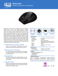
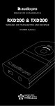
User and installation manual
Voyager 300
Keyboard, Video & Mouse Extender
Installation and
Operation Manual rev. 1
LIMITED WARRANTY
Daxten warrants the Voyager 300 UTP™ to be in good working order for one year from the date of
purchase from Daxten Computer Solutions or an authorised dealer. Should this product fail to be in good
working order at any time during this one year warranty period, Daxten will, at its option, repair or
replace the Unit as set forth below. Repair parts and replacement units will be either reconditioned or
new. All replaced parts become the property of Daxten. This limited warranty does not include service to
repair damage to the Unit resulting from accident, disaster, abuse, or unauthorised modification of the
Unit, including static discharge and power surges.
Limited Warranty service may be obtained by delivering this unit during the one year warranty period to
Daxten or an authorised repair centre providing a proof of purchase date. If this Unit is delivered by mail,
you agree to insure the Unit or assume the risk of loss or damage in transit, to prepay shipping charges to
the warranty service location, and to use the original shipping container or its equivalent. You must call
for a return authorisation number first. Under no circumstances will a unit be accepted without a return
authorisation number. Contact an authorised repair centre or Daxten for further information
ALL EXPRESS AND IMPLIED WARRANTIES FOR THIS PRODUCT INCLUDING THE WARRANTIES OF
MERCHANTABILITY AND FITNESS FOR A PARTICULAR PURPOSE, ARE LIMITED IN DURATION TO A
PERIOD OF ONE YEAR FROM THE DATE OF PURCHASE, AND NO WARRANTIES, WHETHER EXPRESS
OR IMPLIED, WILL APPLY AFTER THIS PERIOD. SOME COUNTRIES DO NOT ALLOW LIMITATIONS
ON HOW LONG AN IMPLIED WARRANTY LAST, SO THE ABOVE LIMITATION MAY NOT APPLY TO
YOU.
IF THIS PRODUCT IS NOT IN GOOD WORKING ORDER AS WARRANTED ABOVE, YOUR SOLE
REMEDY SHALL BE REPLACEMENT OR REPAIR AS PROVIDED ABOVE. IN NO EVENT WILL DAXTEN
COMPUTER SOLUTIONS BE LIABLE TO YOU FOR ANY DAMAGES INCLUDING ANY LOST PROFITS,
LOST SAVINGS OR OTHER INCIDENTAL OR CONSEQUENTIAL DAMAGES ARISING OUT OF THE USE
OF OR THE INABILITY TO USE SUCH PRODUCT, EVEN IF DAXTEN COMPUTER SOLUTIONS OR AN
AUTHORISED DEALER HAS BEEN ADVISED OF THE POSSIBILITY OF SUCH DAMAGES, OR FOR ANY
CLAIM BY ANY OTHER PARTY.
NOTE: This equipment complies with the requirements of European EMC directive 89/336 EEC in
respect of EN55022 Class B, EN 50082-1 and EN 60555-2.
This equipment has been found to comply with the limits for a Class A digital device, pursuant to Part 15
of the FCC Rules. These limits are designed to provide reasonable protection against harmful interference
when the equipment is operated in a commercial environment. This equipment generates, uses, and can
radiate radio frequency energy and, if not installed and used in accordance with the instruction manual,
may cause harmful interference to radio communications. Operation of this equipment in a residential
area is likely to cause harmful interference in which case the user will be required to correct the
interference at his own expense.
© Copyright 2004. All rights reserved.
No part of this manual may be reproduced, stored in a retrieval system, or transcribed in any form or any
means, electronic or mechanical, including photocopying and recording, without the prior written
permission of Daxten Denmark.
IBM ® AT, and PS/2 are trademarks of International Business Machines Corp.
Microsoft ® and Microsoft Windows ™ are registered trademarks of Microsoft Corp.
Multisync is a trademark of NEC Technologies, Inc.
All trademarks acknowledged
2
CONTENTS
Printed in Denmark
version 1.0
Introduction………………………………………………………………………………………...
Features……………………………………………………………………………………
Operation………………………………………………………………………………….
Compatibility……………………………………………………………………………….
Caveat……………………………………………………………………………………..
Getting started………………………………………………………………………………………
Package contents…………………………………………………………………………..
Cable requirements………………………………………………………………………..
UTP/STP Connection cable wiring……………………………………………………….
Quick setup system guide…………………………………………………………………………..
Procedure…………………………………………………………………………………………...
Connecting up………………………………………………………………………………………
Skew……………………………………………………………………………………….
Operation…………………………………………………………………………………………...
Keyboard & mouse emulation…………………………………………………………….
Trouble shooting……………………………………………………………………………………
Keyboard………………………………………………………………………………….
PS/2 mouse………………………………………………………………………………..
Video………………………………………………………………………………………
General Questions…………………………………………………………………………………..
Service information…………………………………………………………………………………
Maintenance and repair……………………………………………………………………
Technical support………………………………………………………………………….
Appendix A. General specifications………………………………………………………………..
4
4
4
4
5
5
5
5
6
7
7
8
9
11
11
11
11
12
12
13
14
14
14
15
3
INTRODUCTION
Thank you for choosing the Voyager 300 UTP™ Designed for ‘Plug & Play’ operation,
your new Voyager will allow you to remotely position your Keyboard, Video Display
and PS/2 Mouse away from your PC’s System unit.
Features
This product has a number of unique features that allow transparent remote operation of
your PC.
• Access your CPU up to 350m/1200 ft away using a single CAT 5, 5E or 6 twisted
pair cable.
• Adjustable double Video Equalisation - Compensates for loss of image quality due
to cable length in any distance.
• Fully buffered signals to ensure consistent remote operation of you PC
• PS/2 keyboard and PS/2 mouse emulation allowing you to ‘Plug & Play’ - Intelligent
keyboard and mouse emulation ensures the PC boots and operates correctly under all
possible circumstances as well as allowing ‘Plug & Play’ initialisation of the remote
keyboard and mouse.
• Dual Access allows for an additional keyboard, monitor and PS/2 mouse through the
local unit.
Operation
The Voyager is simple to install -no software is required. Just connect the units up as
described in quick set up system guide and you're ready to work.
Switch the computer off before wiring.
Compatibility
To operate in various environments and with hardware from many manufacturers, this
product has a number of specific features. This product has been tested with a wide
variety of hardware. However, it is impossible to guarantee correct operation with every
keyboard, monitor, mouse and motherboard currently on the market. Contact Daxten if
you have inquiries
The Voyager is compatible with the following equipment:
• System Unit:
PS/2 and 100% compatible clones. - PC equipped with
PS/2 mouse port*
• Keyboard:
PS/2
• Mouse:
PS/2 Mouse ,Microsoft , Logitech 3 button, Scroll wheel.
• Monitor:
VGA, Super VGA, XGA , QXGA
If your PC does not have a PS/2 mouse or keyboard port, you can use an USB to PS/2
converter. (Ask your Dealer)
Operating system compatibility—The Voyager is compatible with all Windows
operating systems up to Windows 98, 2000, XP, Lindows and some DOS, Linux and
Unix systems.
4
BIOS compatibility
Because of the numerous BIOS systems on the market, and the constant changes in
them and in processor optimizations, mice, and keyboards, it is impossible to guarantee
universal compatibility for the Voyager keyboard/mouse emulation. The Voyager
emulation is compatible with almost all standard PC (Intel/AMD based) BIOS systems,
but the customer is responsible for testing the Voyager with his/her own equipment
within the unconditional return period established by his dealer.
Important note on power supplies/mains adapters
The local unit is normally powered from the keyboard connector with 5 V DC. Some
PC’s do not supply enough power from the keyboard connector; this necessitates the
use of a 5VDC mains adapter on the local unit. The Voyager 300 is equipped with a
DC jack for this purpose; this jack is normally not used, since most PC-s supply enough
power through the keyboard connector.
If you daisychain the local with other gear - please use a separate 5volt
supply (9014-00MS) for the local unit.
Caveat
Because of the constant and rapid changes in operating systems it is impossible for
Daxten to guarantee universal compatibility or compatibility with Windows systems
released after the purchase date of the Voyager equipment.
The customer is responsible for testing the Voyager with his own equipment within the
unconditional return period established by his dealer. After elapse of the test period the
Voyager system will normally not be accepted for return because of compatibility.
It is possible to get new firmware, when new software is released. Ask your Daxten
dealer.
GETTING STARTED
Package Contents
Your Voyager package includes the following
1
1
1
1
1
Voyager Local unit
Voyager 300 Remote unit
5V Power 1,3A supply
CPU PS/2 / VGA Cable 1.8 M
User Manual
part 1034-021L
part 1034-321R
part 9014-00M
part 2095-02
• Only use the power transformer supplied with this product for the remote unit.
5
Cable Requirements
Cables to connect the Voyager Local unit to your PC’s system unit are supplied in the
package. Your keyboard, monitor and mouse will plug straight in to the Voyager
Remote Unit.
The Local Unit to Remote Unit connection cable is not supplied; if you do not have
suitable CAT 5, 5E or 6 UTP or STP cable fitted at you site, please consult your dealer.
The Local and Remote units are connected by industry standard structured cabling
(Category 5, 5E or 6 UTP/STP, 4-pair) terminated with RJ45 connectors.
The cable used should be solid trunk cable. Stranded patch cable will give poor
results over longer distances.
The connector wiring must meet the EIA/TIA 568 standart.
UTP / STP Connection Cable Wiring
The Local-Remote interconnection cable is terminated in RJ45 connectors and should
be wired according to the EIA/TIA 568 (Scheme B preferred) industry standard. The
Voyager will function with other wiring schemes, but the video quality may be
impaired.
Orientation: Looking into the RJ45 socket pin 1 is on the left and Pin 8 on the right.
Pin Wire Colour Wire Pair
1 White/Yellow T2 2
2 Orange
R2 2
3 White/Green
T3 3
4 Blue
R1 1
5 White/Blue
T1 1
6 Green
R3 3
7 White/Brown
T4 4
8 Brown
R4 4
1
8
The Voyager has been tested with all major makes of CAT 5 cable including BICCVERO, Mohawk, and Brand-Rex. The Voyager has also been tested with most major
makes of CAT 5E and CAT6 with good results.
Note: That failure to wire the twisted pairs correctly will impair the video quality
dramatically and / or prevent correct operation.
This Voyager 300 extender is designed for use up to a maximum cable length of
350m/1200ft At this length the video quality should still be acceptable even at a screen
resolution of 1200x1600 (75Hz). At distances over 100 m You might need a Skew
Compensator. It depends on your cable cat5 or cat6 and monitor resolution.
Although a single continuous length of interconnect cable is preferable, operation is
possible through multiple Patch Panels. However, the more patch panels the cable is
routed through, the greater the chance of video signal degradation.
6
QUICK SETUP SYSTEM GUIDE
VGA out
UTP in
9-20V DC KEY MOUSE
UTP
KEY MOUSE
5 V DC
Monitor
PROCEDURE
The Voyager consists of a Local and a Remote Unit interconnected by a single
structured cable that carries all the necessary signals. The Local unit is connected to the
PCs keyboard, VGA ports and PS/2 mouse. The keyboard, monitor and mouse are
connected directly to the Remote Unit. The Remote Unit is powered by a power supply
whilst the PC powers the Local Unit. An optional local PSU is available for PC’s that
do not have enough power available on the keyboard port.
We recommend that the complete system should be tested in one room before
permanent installation. If a long interconnect cable is not available, use a patch
lead to test basic unit operation with your PC.
7
CONNECTING UP
The Quick system guide illustrates how the units are interconnected.
1. Switch off your PC
2. Connect the local Voyager, keyboard, monitor and mouse as shown in the
appropriate diagram (page 8). You can use the local without mouse, keyboard
and monitor.
3. Connect the UTP cable between the local and remote
4. Connect the mouse keyboard and monitor to the remote.
5. Power up the Remote Unit by connecting the supplied mains adapter and
switching it on.
6. Power on your PC and operating system
7. Check keyboard operates correctly.
8. Check that the mouse functions works right
9. The Remote Unit contains video equalisation circuitry that compensates for loss
in image quality experienced when driving over long cables.
To set the correct level of equalisation there are two adjustments on the front
side of the remote unit. adjust the distance appropriate to the cable length
adjust the Eq. Fine tune the distance again.
Distance Eq.
Cable Length (m)
Cable Length
(ft)
LED
0 – 100 m
0-350
No light
80-220 m
250-725
LED 1 ON
190- m
600-
LED 2 ON
Cable Length distance Setting
The remote unit (when installed in its final location) may be left permanently powered
up.
Please note that for all practical purposes cable equalisation cannot be exact - the
remote image will never be as sharp as the original.
To make the distance setting easy as possible we have incorporated distance setting and
three boost steps. It means that you will feel a big gain jump when the LED’s change.
If you are in the changing area try adjust the EQ level before and after the LED’s has
changed distance area to achieve the best picture.
If you are dealing with CAT6 and cables under 100 meters the local can be modified to
get an even better picture.
The LED’s are guidelines because cables differ in quality
Adjust the Distance afterwards the Equalizer EQ,
8
SKEW
Picture quality can be improved when using a skew delay compensator, at long
distances over 100 meters and higher resolution than 1024X768 the picture can be
improved.
Launch a black text on white background look out for colour change. If you have any
colour shades on your picture install a Skew delay compensator next to the remote.
AA
colour shade
The shade appears when the pairs inside of the CAT5/6 cable are different lengths. The
phenomenon is visible over long distances combined with high resolutions.
You can use a test image with 3 colour bars, red green and blue or Daxten test program
supplied with the delayline. On the Homepage you can find the Delayline and launch
the test picture.
To the right you see green is
aligned most to the right. By
adding delay to red and green
they will walk to the right and
all colours will stay aligned.
It is possible to buy skewles
cables - they are not suitable for
network traffic and more
expensive.
9
VGA in
UTP in
9-20V DC KEY MOUSE
10
VGA out
UTP
Monitor
VGA out
KEY MOUSE
5 V DC
Keyboard & Mouse Emulation
The Voyager uses a microprocessor to emulate the keyboard and mouse. It is not
necessary to have any keyboard or mouse connected to local unit either at start-up or
during use.
Some mices and keyboards need to be plugged in before boot up.
Do not mix 2 button and three button /scroll mices because it might confuse the
operating system. Normal you can hot plug your mouse and keyboard into the local and
remote Voyager.
Some mice’s do not initialise unless you disconnect the supply shortly.
Keyboard
• The PC boots fine with no error messages but the remote keyboard does not
work at all
a) Cable is loose, replug keyboard cable.
b) Wrong cable plugged in, keyboard and mouse cables reversed.
c) Try a different model of keyboard. If the new keyboard works then
original one may be incompatible (some older auto-sensing units may not work with
this product).
• Wrong or missing characters from those typed.
a) Reconnect the remote power supply.
b) Power down and reboot the entire system with mouse and keyboard connected.
• The PC always comes up with ‘Keyboard Error ’ or No keyboard found
a) If the system appears to work fine after pressing F1 (or ESC) adjust your BIOS setup so that the PC does not test the presens of a connected keyboard.
Some wireless keyboards are not supported!
PS/2 Mouse
•
a)
b)
c)
d)
•
A mouse cursor on the screen, but the mouse does not work
Cable is loose, replug mouse cable and press
Wrong cable plugged in, keyboard and mouse cables reversed.
Try a different model of mouse.
Power cycle the remote unit.
The system does not detect a PS/2 mouse, or the application cannot find the
mouse.
a) Wrong cable plugged in, keyboard and mouse cables reversed on Local Unit.
b) Cable is loose, replug mouse cable between Local Unit and CPU.
c) Ensure that the keyboard input cable to the Local Unit is connected to provide
power.
d) Reboot PC.
• The mouse movement is erratic
a) Try installing a Microsoft Intellimouse mouse driver, which can automatically
correct out of sync mice.
b) Keyboard & Mouse
• Neither the keyboard or mouse operate, or have locked up
11
a) Reset remote by unplugging the power supply.
b) Reset PC and the Extender Remote unit.
c) Some PC’s have a port re-mapping feature that allows a keyboard or mouse to be
plugged into either PS/2 port. Try crossing over the cables between the local unit and
PC i.e. KB to Mouse & Mouse to KB.
Video
• The picture is not sharp & is very smeary
a) Video compensation incorrectly set. Delayline/s kew compensator not used - See
installation section.
• The Picture is not rolling up and down horizontal stripes.
a) Local unit needs external 5V supply (See page 5).
• Each character has separated into overlapping red, green & blue pixels, (the
effect is like looking through 3D glasses).
a) Check that the UTP / STP wiring used throughout is EIA 568 standard.
b) Check patch panels for poor or incorrect connections
c) Check the compensation dipswitch settings.
• The monitor sometimes loses sync causing it to go blank for a second or two
a) This occurs if your electrical power system is very noisy (particularly ground).
• Video only required, but no picture appears
a) The Local Unit must be connected to a power supply or PC keyboard port.
b) Consult technical support if you cannot do this and require a secondary power supply
for the Local Unit.
• A constant vertical wobble appears down the screen (interference).
a) The interconnection cable could be located too close to a source of very strong mains
borne interference, re-route cabling if possible
If interference is from strong signals from a nearby broadcast transmitter a beat pattern
will appear. Change the vertical refresh rates slightly, such as from 60Hz to 70Hz.
• Video Picture is black and white not colour
a) The problem could be Monitor ID.
b) If your graphics card supports VESA DDC (Display Data Channel) configure the
graphics driver by explicitly telling it make and model of monitor you have rather
than using DDC.
• Video Resolution goes low when connecting trough Voyager
a) Video resolution is lower than the resolution adjusted on the video card, when
connecting through the voyager.
. The ID negotiation is not transferred over the UTP. Select monitor size and driver
manually in the OS. The switch down trick is performed by the VGA adapter to
secure the CRT is not destroyed at to high resolutions.
12
GENERAL QUESTIONS
• Is it possible to use a cable length of more than 300m?
The Voyager has been designed to produce acceptable results with Super VGA
resolutions at the maximum cable length 400M. It may be possible to run up to 400
meters. The signal needs to bee restored. So the maximum is 400 m in 1024x768 at
75hZ. It depends on the cable quality. Cat 6 is designed for 200MHZ bandwidth Cat5
Works only in 100MHZ
• Why do I have a skew delay in my cables
The pairs inside the cable are twisted different to reduce cross talk. Cat6 use more twist
than cat5. When you increase the resolution the need for compensation raise.
Can Voyager units be chained to allow operation over more than 400m/1200ft?
Daisy chain gives delay on mouse and keyboard functions and equalisers is required. If
you plan to cascade units, please contact technical support to discuss your application.
• Can I add several working spots to one PC ?
Yes use one USB/PS2 converter for every local. The local units will obtain their own
HID number from the OS. Please remark USB dongels behave different and might not
work with the OS or the local unit. Please contact technical support to discuss your
application.
• Which cable is better UTP or STP?
UTP cable will give the best quality video over long distances because it has less
capacitance per unit length. However, STP may be a better choice in electrically noisy
environments.
• When using UTP what is the best way to ensure the system does not suffer from
any interference?
This product is designed to withstand high levels of interference whilst using UTP over
long distances. To further reduce the potential for interference consider the following:
a) Ensuring that the computer and remote monitor are both connected to the same
mains phase.
b) Ensuring that the AC voltage across the mains grounds (at the local PC & remote
monitor) is less than 2V.
c) Using a clean earth system (if your site has one installed).
d) Routing the interconnection cable away from other cables.
e) Trying STP cable if you think noise could be a problem.
• Is the Voyager suitable for use between buildings?
The Voyager does not have line isolation. Therefore, operation between buildings is not
recommended.
•
Is the Voyager connectable to my network?
13
The Voyager uses the same cable as your network, but it cannot be connected into your
network in any way. The Voyager must have dedicated cables in the network.
Connecting other equipment on the same cables as the Voyager voids the
guarantee and may damage the Voyager.
SERVICE INFORMATION
Maintenance and repair
The unit does not contain any user-serviceable parts inside. Any malfunction of the unit
should be reported to a factory-authorised repair centre for service. Any discrepancies
in the operation of the unit according to this manual should be reported to the Technical
Support Department of Daxten Computer Solutions.
Technical support
If you cannot determine the nature of a problem, please call Daxten Computer Solutions
and ask for Technical Support. If possible call from a phone located near the unit we
may be able to solve your problem directly over the phone. If we cannot solve your
problem, and determine that the fault is in the unit, we will issue a Return Material
Authorisation (RMA) number that must appear on the outside of all returned products.
The unit should be double-packed in the original container, insured, and shipped to the
address given to you by our Technical Support representative.
14
APPENDIX A. GENERAL SPECIFICATIONS
Size
Voyager 300
Local & Remote Units:
210 x 100 x 45 mm (8.27 x 3.94 x 1.77 in.)
Weight
Local Voyager
350 g
Remote Voyager300 355 g
Local Unit: from PC or
optional 5V DC 800mA regulated PSU
Remote Unit: Running >530 mA
Recommended PSU 1A/5V low ripple.
CAT 5, CAT 5E, Cat 6 Solid UTP/STP
EIA/TIA 568 Wiring
RJ45 Connectors
Input Power
Interconnect Cable
Video Bandwidth (-3dB)
Maximum Resolution
Video I/O
Video Compatibility
Video Compensation
Video Coupling
Sync H/V
Keyboard Compatibility
Mouse Compatibility
Local Unit: 150MHz
Remote Unit: 230 MHz
1600 x 1280@ 85 Hz 450M in cat6 / 350 M cat5
1280 x 1024 @ 85 Hz (to 350 meters/ 1150 ft)
1024 x 768 @ 85 HZ (to 400 meters/1300 ft)
800 x 600 @ 75 Hz (to 600 meters/2000 ft)
1.0 V P-P
VGA, Super VGA, XGA
4-Stages in 4 ranges
DC
Separated TTL level
Console switch Time Period
PS/2
Standard PS/2 2 Button, Microsoft Intellimouse
and Logitech PS/2 3 Button Wheel mouse
<1 second
Kit
Weight
WHD
Voyager 300
1,150kg.
25 x 17 x 6 cm
Please note that these specifications are subject to change without prior notice.
15
www.daxten.com
USA
Daxten LLC
811 W. Evergreen Ave
Suite 302A
Chicago, IL 60622
USA
IRELAND
Daxten Ltd
Unit 5 Distribution Centre
Shannon Free Zone
County Clare
IRELAND
Tel.: (312) 475 0795
Fax: (312) 475 0797
Tel:+353 (0)61 23 4000
Fax: +353 (0)61 23 4099
[email protected]
www.daxten.us
[email protected]
www.daxten.ie
FRANCE
Daxten
B.P. 04
77, Route de Cheptainville
F-91630 Marolles-en-Hurepoix
FRANCE
GERMANY
Daxten GmbH
Salzufer 16, Geb. B
10587 Berlin
GERMANY
UNITED KINGDOM
Daxten Ltd
4 Harp Business Centre
Apsley Way
London NW2 7LW
UNITED KINGDOM
Tel: +49 (0)30 85 95 37 0
Fax:+49 (0)30 85 95 37 99
Tel: +44 (0)20 8438 3800
Fax:+44 (0)20 8438 3899
[email protected]
www.daxten.de
[email protected]
www.daxten.co.uk
SWEDEN
Daxten Sweden AB
Ostmästargränd 10A, 1tr,
120 22 Stockholm
SWEDEN
SWITZERLAND
Daxten GmbH
Seebahnstr. 231
8004 Zürich
SWITZERLAND
Tel.: +46 (8) 692 65 73
Fax.: +46 (702) 636 982
Tel.: +41 (0) 43 243 32 11
Fax: +41 (0) 43 243 32 16
[email protected]
www.daxten.se
[email protected]
www.daxten.ch
Tel: +33 (0)1 64 56 09 33
Fax:+33 (0)1 69 14 88 34
[email protected]
www.daxten.fr
DENMARK
Daxten
Finlandsgade 33
8200 Aarhus N
DENMARK
Tel: +45 70225411
[email protected]
www.daxten.dk
AUSTRIA
Daxten Handel Ges.m.b.H.
Künstlergasse 11/4
A-1150 Wien
AUSTRIA
Tel: +43 (0)1 879 77 65
Fax:+43 (0)1 879 77 65 30
[email protected]
www.daxten.at
SPAIN
Daxten Computer Solutions
S.L.
C/Florian Rey, 8
50002 Zaragoza
SPAIN
Tel: +34 9 02 197 662
Fax:+34 9 76 201 633
[email protected]
www.daxten.com.es
GREECE
Open Minded Systems (OMS)
Mr. Christos Stamoulis
83 Priamou str.
GR-17343 Ag. Dimitrios
Greece
Fon 00302109769393
Fax 00302109769394
mail : [email protected]